background image

®

Table of Contents (English)

  1. Packing List ......................................................... 1

  2. Specifications ...................................................... 1

  3. Precautions ......................................................... 2

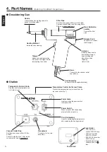
  4. Part Names  (Desoldering Gun/Station) ............ 3
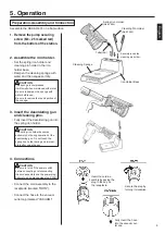
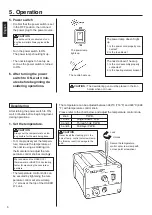
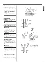
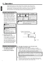
  5. Operation 

(Preparation- 

Assembly and Connection) .... 4 • 5

(Desoldering) ........................... 5 • 6

(Cleaning during Operation) ......... 7

(Problems during Desoldering) . 7• 8

(Post-operation Maintenance) ...... 8

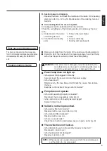
(Troubleshooting Guide) ............... 8

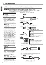
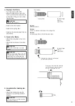
  6. Maintenance  (Desoldering Gun) ................. 9 • 10

(Station) .......................................11

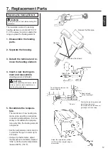
  7. Replacement Parts

(Replacing Heating Element)...... 12
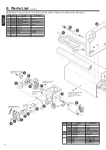
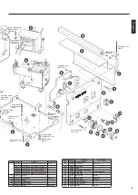
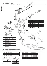
  8. Parts List 

(Station) ............................... 13 • 14

(Desoldering Gun) ...................... 15

  9. Replacement Parts ............................................ 15

 10. Wiring ................................................................ 16

l

Thank you for purchasing the HAKKO 474 Desolder-

ing Tool.

Please read this manual before operating the HAKKO 

474. 

Keep this manual readily accessible for reference.

l

 CAUTION 

Remove the pump securing screw (M4

×

25 

marked red) from the bottom of the station. 

Failure to do so may result in serious prob-

lems.

吸錫槍

Instruction Manual

使用說明書

日本白光牌

目錄 ( 中文 )

 1. 包裝清單 ......................................................................... 17
 2. 規格 .................................................................................. 17
 3. 安全及使用上的注意事項............................................ 18
 4. 部件名稱 (吸錫槍/控制臺) ..................................... 19

(準備 --- 裝配和連接) .......................20.21
(吸錫) ..................................................21.22
(使用時 , 進行清理工作) ......................... 23
(除錫時發生故障) ....................................... 23
(使用後的保養) ......................................... 24
(排除故障指南) ......................................... 24

 6. 保養 

(吸錫槍) ..............................................25.26
(控制臺) ...................................................... 27

 7. 更換部件 ......................................................................... 28
 8. 部件清單 (控制臺) ..............................................29.30

(吸錫槍) ...................................................... 31

 10. 電路圖 ............................................................................. 16

承蒙惠顧 , 謹致謝忱。
使用 HAKKO 474 之前 , 請詳閱本使用說明書 , 正
確使用。
閱後請妥為收存 , 以備日後查閱。

 注意 

使用之前必須除去機身底下的泵拴緊螺絲

(M4×25 紅色記號 ), 否則可能導致嚴重後

果。

English

中   文

Summary of Contents for 474

Page 1: ...Replacement Parts Replacing Heating Element 12 8 Parts List Station 13 14 Desoldering Gun 15 9 Replacement Parts 15 10 Wiring 16 l Thank you for purchasing the HAKKO 474 Desolder ing Tool Please read...

Page 2: ...80kpa 600 mm Hg 24 in Hg 15 l min 2mV typical 0 6mV 2 165 W 135 H 260 D mm 6 5 5 31 10 24 in 3 8kg 8 4lb Part Name Part No Power consumption Temperature range Insulation resistance Nozzle inside diame...

Page 3: ...ff and allow the unit to cool to room temperature To prevent damage to the unit and ensure a safe working environ ment be sure to comply with the following precautions l Do not use the unit for applic...

Page 4: ...nects to the vacuum outlet cap station Cord Assembly Connects to the receptacle station Temperature Control Knob Provides nozzle temperature con trol refer to p 7 Temperature Control Set Screw Clamp P...

Page 5: ...ore use Be sure to remove the round portion of the sponge 3 Insert the desoldering gun and cleaning pins Fully insert the desoldering gun into the spring iron holder CAUTION The spring iron holder bec...

Page 6: ...ore beginning desol dering operations 1 Set the temperature CAUTION Always set the temperature to as low as possible for the work being done To more precisely set the tempera ture measure the temperat...

Page 7: ...nside of the hole and the backside of the P W B If this is difficult to do try slowly moving the lead with the nozzle If the lead moves the solder is melted CAUTION Never move the lead by force If it...

Page 8: ...w filters han dy and replacing the installed filter pipe with this backup filter pipe 3 Replace the entire filter pipe with he provided backup filter pipe 2 Pull 1 Down Normal Blue or slight amount of...

Page 9: ...ed it must be replaced by the manufacturer its service agent or similarity qualified person in order to avoid personal injury or damage to the unit l Power lamp does not light up Is the power cord plu...

Page 10: ...he inside hole and the surface of the nozzle is plated with a special alloy Should this alloy become eroded by high temperature solder the nozzle will not be able to maintain the proper temperature 2...

Page 11: ...thirds of the spring filter Replace Ceramic paper filter is stiff with flux and solder 4 Replace the filters Turn the power switch OFF When the filter pipe is cool to the touch push down the release...

Page 12: ...Assemble the pump heads Reassemble the valve plate and fixing plate CAUTION When assembling the pump be sure to check for air leaks VACUUM Ceramic Paper Filter S No A1009 Filter Retainer Remove the fi...

Page 13: ...ture The resistance of new heating ele ment varies resulting in variations in operating temperatures It is nec essary to recalibrate the tempera ture every time the heating element is replaced Set the...

Page 14: ...over for securing screw Receptacle Knob Front panel Cover Handle Temp control set screw clamp P W B Specifications 10 pcs W O ring S20 Set of 4 One side One side W potentiometer Part No B2063 B2065 B2...

Page 15: ...M4 8 2 Spacer nominal size 4 25 Pan Head Screw M4 25 Hexagon Nut M4 4 Spring Washer nominal size 4 4 Pan Head Screw with Washer M4 8 Pan Head Screw M5 10 4 Tapping Screw M2 6 6 4 Tapping Screw M2 6 6...

Page 16: ...Nozzle 1 6mm 0 06 in Part No A1002 A1003 A 0 8mm 0 03 in 1 0mm 0 04 in B 1 8mm 0 07 in 2 0mm 0 08 in Part No A1004 A1005 A1006 A1007 A 0 8mm 0 03 in 1 0mm 0 04 in 1 3mm 0 05 in 1 6mm 0 06in B 2 3mm 0...

Page 17: ...0 Wiring 1 1 4 4 1 2 2 M1 4 3 2 1 TR M2 TRANS H2 TRANS H1 24V 1 Receptacle Fuse Holder Transformer White Black Power Switch Power Cord Motor P W B 10 1 1 4 4 1 2 2 M1 4 3 2 1 TR M2 TRANS H2 TRANS H1 2...

Page 18: ...1 2 4 3 1 0mm 1 1 1 1 0mm 1 1 1 1 HAKKO 474 1 0mm 1 0mm 2 HAKKO 474 100W 474 AC 24V 80KPa 600mmHg 15l min 2 2mV 165 W 135 H 260 D mm 3 8Kg 809 C1183 AC 24V 50W 380 480 420 300M 1 0mm S 135 W 174 H mm...

Page 19: ...3 18 1 2 M4 25 380 480 HAKKO...

Page 20: ...4 19 29 30 31 A1033 23 21 21 A1009 100V 110V 125V 2A 120V 250V 2A U 220V 230V 250V 1A 240V 250V 1A S...

Page 21: ...20 5 B1094 B1095 HAKKO 474 1 M4 25 2 3 4 IRON VACUUM...

Page 22: ...21 1 2 1 2 5 6 3 5 3 1 HAKKO 191 HAKKO 192 HAKKO 474 380 480 1 2 3 4 5 6...

Page 23: ...22 2 3 4 5...

Page 24: ...23 1 HAKKO 475 HAKKO 475 HAKKO 475 2 1 3 3 2 1 A B A 70 80 25 25 5 25...

Page 25: ...24 HAKKO 474 B 25_26 20 25 26 24 20 28 a b c d e f...

Page 26: ...6 25 HAKKO 474 1 2 3...

Page 27: ...26 6 A1033 A1033 4 A1033 5...

Page 28: ...27 1 A1009 2 1 2 3 A1009 S20 6 VACUUM...

Page 29: ...28 7 23 2 4 1 2 3 4 24V 50W 5 1 3 CAL 380 CAL...

Page 30: ...1A 220 230V 250V 1A S 240V 250V 2A U 120V 14 15 16 17 18 19 1 2 3 4 5 6 7 8 9 10 11 12 13 8 29 B1029 A1009 B1063 B1031 B1034 B1038 B1036 B1028 B2061 B1093 B1061 B1044 B2057 S20 10 S20 1 4 B2063 B2065...

Page 31: ...081 B2082 B2083 B2490 B3505 B2066 B1037 B1084 B1078 B1053 B1312 4 27 28 29 30 31 32 33 34 35 36 37 38 39 B1057 B2060 B2059 B2058 B2085 A1013 B1056 A1014 B1050 B1059 B1313 B1064 B2506 2 2 2 2 M3 6 2 M4...

Page 32: ...313 A1003 B1723 B1724 B1094 B1095 A1042 B1470 B3048 4 24V 50W S 1 0mm 23 24 22 21 25 OVERSEAS AFFILIATES U S A AMERICAN HAKKO PRODUCTS INC TEL 661 294 0090 FAX 661 294 0096 Toll Free 800 88 HAKKO 4 2...

Reviews: