background image

Summary of Contents for RPC-2000

Page 1: ...he United States of America All rights reserved Contents of this publication may not be reproduced in any form without the written permission of the copyright owner IBM IBM PC 1 PC XT 1 and PC AT as u...

Page 2: ...Introduction 2 2 RPC 2000 Channel A Connector Pin Out 2 3 RPC 2000 Channel B Connector Pin Out 2 4 Connecting the RPC 2000 to Your Radio Equipment 2 4 1 Connecting Channel A to an External 10 10 14 15...

Page 3: ...res 36 36 3 7 37 38 38 40 TECHNICAL DESCRIPTION 4 2 6 1 6 2 Specifications 42 44 4 4 44 Circuit Description Overview 6 2 1 PC Buss Interface Circuitry 6 2 2 Timer and Interrupt Circuitry 6 2 3 Serial...

Page 4: ...terface Circuitry 47 FIGURE 10 Timer and Interrupt Circuitry 48 FIGURE 11 Serial Communications Controller SCC Circuitry 49 FIGURE 12 Push to Talk PTT and System Indicator Circuitry 50 FIGURE 13 RPC 2...

Page 5: ...m HF performance The RPC 2000 does not require use of any of the asynchronous RS 232C serial I O ports of the terminal or PC compatible Rather the RPC 2000 makes use of the synchronous data ports of t...

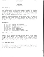
Page 6: ...pters you will learn how to install connect and operate your RPC 2000 Chapter 1 covers RPC 2000 installation this chapter should be CAREFULLY reviewed before installing the RPC 2000 into your DS 3200...

Page 7: ...0 0 0 N I u z P J 0 H 8 1 rl 1 r r l 8 z 0 H H fJ 1...

Page 8: ...List 1 934 02000 1 865 02001 1 870 02001 1 333 20090 1 333 51218 1 333 10250 1 333 51228 2 333 74564 RPC 2000 Circuit Board RPC 2000 Software Diskette RPC 2000 Instruction Manual DE 9P Connector DE 9...

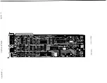
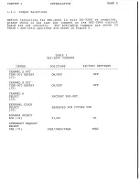
Page 9: ...he available jumpers are shown in Table 1 and their positions are shown in Figure 2 JUMPER TABLE 1 RPC 2000 JUMPERS POSITIONS FACTORY SETTINGS CHANNEL A PTT TIME OUT DEFEAT J1 CHANNEL B PTT TIME OUT D...

Page 10: ...B MODEM RXD DS3 QUJJ_QiliJi OUTPUT LEVEL D R21 2 R12 CH A MODEM RXD 0 GND DS4 3 4 I 5 I J4 J3 ilil 6 I ADDRESUilli l JS S2 S GND 0 7 JS INTERRUPT LEYEL J7 1f 5Si i Q 0 0 0 NW_ I 8 CHANNEL B CHANNEL A...

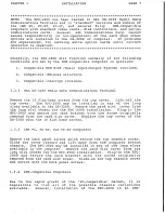
Page 11: ...cover Lift off the top cover The RPC 2000 may be installed in any of the long slots available in the DS 3200 Remove the card slot cover from the long slot chosen for the RPC 2000 installation Plug in...

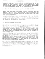
Page 12: ...back up copies of this diskette BEFORE attempting operation It is HIGHLY RECOMMENDED that you place a write protect tab on the HAL RPC 2000 diskette This will help prevent accidental erasing of the o...

Page 13: ...oftware for resale or any other use other than with the supplied RPC 2000 circuit board will be vigorously prosecuted to the full extent of the copyright laws After the RPC 2000 circuit board is insta...

Page 14: ...e contact your HAL dealer or HAL Communications Corp directly for this option Please note that for high performance HF packet an external modem is highly recommended When the M2 RPC option is installe...

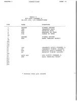
Page 15: ...ECTIONS NAME GROUND TXD RXD RTS CTS GROUND DCD TCA ST RCA RT APTT OUT DTR FUNCTION SIGNAL GROUND TRANSMIT DATA RECEIVE DATA REQUEST TO SEND CLEAR TO SEND SIGNAL GROUND DATA CARRIER DETECT TRANSMIT AUD...

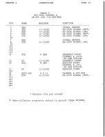
Page 16: ...TS 12VDC RS 232C SIGNAL IN 6 7 GND SIGNAL GROUND 8 DCD 12VDC RS 232C SIGNAL IN 9 10 11 12 13 14 TCA 0 DBM TRANSMIT AUDIO CHANNEL A OUT 30 DBM TYPICAL 15 ST 12VDC TRANSMIT TIMER 16 RCA 0 DBM RECEIVE AU...

Page 17: ...CB TRANSMIT AUDIO CHANNEL B GND SIGNAL GROUND Denotes this pin unused TABLE 5 RPC 2000 CHANNEL B DE 9S J9 I 0 RATINGS MAXIMUM FUNCTION 1 2 3 4 5 6 7 8 9 RCB 0 DBM GND BPTT OUT O C GND TCB 0 DBM GND De...

Page 18: ...re 3 below shows the Channel A signal definition on the DB 25P connector J8 I I 2 I 3 I I 5 I I 7 I RPC 2000 CH A J8 1 DB25P B 14 f 1 GNO B TCA ST f 2 RS232 TXD 15 f f 3 RS232 RXD RCA 16 f 1 4 RT RS23...

Page 19: ...DE 9S connector J9 I I 2 I 3 I 4 I s I I 7 I A 1 RPC 200Q CH B J9 DE9S J B u KCB GND GND TCB 1 GND BPiT OUT c c 1 D D REV DATE W P Elfi HAL CDHHUNJCATJONS CORP BOX 365 ll 61801 RPC 2000 CHANNEL BSlGN...

Page 20: ...al HF Modem The RPC 2000 Channel A DB 25P connector J8 may be connected to an external HF modem for higher performance packet radio operation on the HF bands Your modem of choice should be capable of...

Page 21: ...acket at the present time The only consistent factor among these four 4 tone sets is the use of the CENTER FREQUENCY to specify the tones Listed in TABLE 6 below are the typical tone sets in use on HF...

Page 22: ...l RS232 RTS 1 l 4 I 5 1 1 RS232 CTS I 5 I 1 I I PTT OUT 19 f I I 19 TERH KOS 7 I I GND T 6 I c B 1 I RS232 DCD I 7 I I I I I c I I I I I I I I I I I I I I I I I I I I _ D D REV DATE APP Dlfll HAL COM...

Page 23: ...annel A to your HF transceiver for HF packet operation This configuration for HF operation would provide lesser performance than with the external HF modem M I I 1 I Iu I II G D o o 0 0 _ g Cl ti t zc...

Page 24: ...il cO 1 1 z 0 H z 0 u I 0 jJ u Ul Ill 3 L 0 0 0 I u t 11100 Q Ql l I I 1 1 C j a 1 1 lllH C j jJ t mava JHA u Q r IJ 1 1 cO C j jJ u u 0 If I 0 iJ 1 1 0 1 1 O jJ N 0 NU u I Q I 8 l I Ul l 111 E t M Pl...

Page 25: ...udio lines Also please check on the TYPE of connector used at the radio Most often these connectors are either of the 4 pin mic 6 pin mic 8 pin mic 12 pin mic or RCA phono jack type of connectors AGAI...

Page 26: ...re always available to assist the operator as well The Converse mode displays actual communications We shall first cover how to load the software and then proceed to the command tree and actual operat...

Page 27: ...terrupt level is available for use on your PC for the packet system It selects the interrupt level and indicates on the screen which level has been selected During all of these initial operations the...

Page 28: ...h g cron r del x lfo cld sendpa c I I ltd po clen fro ck retry txdel I in t I t tok I MO Xfl L I Myc l I link J connect Ldisconnect hbnud SModeM f vers o utset I I I okcon pa rMs co lpth I I I chnl d...

Page 29: ...irst digipeater station a comma and the call of the second digipeater etc Disc Disconnect from the current link May also use Alt D at any time in the RPC 2000 program Hbaud Select the data transfer ra...

Page 30: ...allpath The ESC key sets the configuration for that callpath to the current system configuration Xfer Select more transfer commands levels Xfer commands are xmit monit files unprot Xmit Transmit comma...

Page 31: ...he amount of time that the RPC 2000 waits for an acknowledgement of a frame before it sends the frame again Default Frack is 6 seconds Retry Set the maximum number of retrys before stopping from 0 to...

Page 32: ...er and this will allow them to be passed through as data The Default Pass character is 16 hex Ctrl V or SYN character Senpac Select the sendpacket character from 00 to 7F hex This is the character tha...

Page 33: ...special entry that includes ANY call The other special entry available is None which will exclude any call Budlst Ignore or display packets from stations in the call list The Default is DISPLAY Files...

Page 34: ...nt Both Devices Busy Digip Select the ability of this station to function as a digipeater Toggle ON or OFF with the space bar When ON this station can be used as a relay point for other stations When...

Page 35: ...eset clears transmit and receive buffers closes any open files and resets the protocol to the default parameters Quit When selected allows you to exit the RPC 2000 program if you select Y at the promp...

Page 36: ...leading zeros If you do not assign a substation number the RPC assumes that you are the main station for that call and automatically assigns 0 as the suffix Enter a 11 CR 11 to end the call and set My...

Page 37: ...call station XXXX After setting Hbaud parameters return to Link level commands with the ESC key Choose Connect Enter the callsign XXXX When you are ready to connect type a CR carriage return and the R...

Page 38: ...s for the callpath being set will duplicate those of the default settings You may toggle between the various options for these parameters using the space bar When the parameter is set for the desired...

Page 39: ...ating through repeaters designed for voice operation Voice operation repeaters are usually designed to stay active for a short time after the last transmission ends This hang time should be taken into...

Page 40: ...put from the optional Channel A 7910 integrated circuit modem This controls the audio output level to the DB 25P connector used for HF or secondary VHF connection Each output level potentiometer is fa...

Page 41: ...ting it However inadvertent blockage of the ventilating holes in the HAL DS 3200 Radio Data Communications terminal or IBM PC compatible computer will cause the INTERNAL temperature of the terminal or...

Page 42: ...ther transients on the power line or station antenna system A good lightning protection system may help as will disconnecting the terminal or computer during electrical storms However such things are...

Page 43: ...to a copper ground rod which is driven into the ground near the station site 4 This provides a reasonably good D C ground but does little as a RF ground The driven ground rod technique is impor tant...

Page 44: ...e associated with the failure Does it only happen in receive transmit or both 6 Are there any extenuating circumstances Lightning spilled liquids or dropped unit 7 Is there anything else you can add t...

Page 45: ...West Kenyon Road Urbana IL 61801 PAGE 41 Because of the complexity of the circuitry used in the RPC 2000 we do NOT recommend that you personally undertake repair of the circuit board For the convenie...

Page 46: ...dem 1 Additional 300 1200 BPS Internal Tone Modem Packet Radio Channel B DE 9S Connector J9 Type 7910 I C 300 1200 BPS 300 BPS 1270 1070 Hz or 2225 2025 Hz 1200 BPS 1200 2200 Hz Input 30 dbm to 0 dbm...

Page 47: ...4 00 10 16 em with 62 contact edge connector Software furnished on one 5 25 DSDD 360K diskette 75 lbs 34 kg net 3 0 lbs 1 36 kg shipping weight Specifications are subject to change without notice HAL...

Page 48: ...itry Please refer to schematic diagram A1674 Figure 10 This circuitry generates the timer outputs and interrupts A 74LS393 U25 divides the DS 3200 or PC clock rate to the proper rate for the timer chi...

Page 49: ...ndicate the state of TXD RXD DCD and PTT for each of the RPC 2000 channels Two 74LS374 integrated circuits U11 and U21 are used to set the AM7910 modem integrated circuits UlO and U20 The MCO to MC4 o...

Page 50: ...C 2000 Connector Pin Outs and Connector RF Bypassing Please refer to schematic diagram Al678 Figure 14 This contains the connector pin outs for the DE 9S connector J9 and the DB 25P connector J8 Also...

Page 51: ...sec Sl SRD J lORD EN 74LSJ2 ct Foo sz s 0 2 6 PC O JR lt PClORD C6 PCRESET 6 PCAEN 6J PCA9 6 PCA8 RESET 5 Ul6 IDW R 2 rDR D 2 All 1 lC AEN 7 As lQ IR lORD Ul6 A9 l Ul6 A6 r 74LS04 J7 2 INT Lo o tRa2 6...

Page 52: ...QRO ___ 2Z m TIMER ___ t AJ l AQ U25 U2l 82 54 74UJ93 1 tNT J 74LS32 10 U22 4 BPTT _______ J D7 4 APTT D os L STATUS J 1REV 1 DATE 1 API 1 n HAL coHHUN CATroNs coRP l1LJ BOX 365 URBAN L 61801 RPC 2000...

Page 53: ...A DCD S E c 00 S LA 4 0 5 PUI Ll en PULL2 H 00 t 3 JJ L H 12 V 0 z TXDA t 3 C t l RSTXD t l2V z illA H dB RSRTS l 1 t l t l C E 0 z t 3 Q 0 l 1 l2V tiE us a I C28 RSDTR Q RSCTS H I ootur tU rn t 3 H 0...

Page 54: ...3 HDCDI PTTJ VlltoflR PTTJ lr 74LS244 ID4 1 C26 OOhF lH4752 I JPTTOUT PTT 2 D3 1H41 5V D7 D6 D5 1 4 D3 De Dl 1 14111EMJ 1 iiEE1 PTTJ g 11HC4 IMC3 O tHea IHCl C5 IIMDI C5 5V D6 dt qt ffii 05 d2 D4 AMC...

Page 55: ...4 576 HHZ I H I C7 N cs 0 I SpF I DpF l 1 0 0 t J tr 1 Rl2 25DK o 1 0 E PlLU 3 I U RESET H 1 cJ 8 0 CIO RIO H J HRXDB Juf TCll 0 s 3 MTXDJ z 0 C27 3 I t J t2V tr 1 IJID s r AH7910 C2 3 Jul K I RCB C6...

Page 56: ...6 J_8 7 NlrTOUT 4 J RSDC D I RSDTR J J I 2 l _ 24 t 5 Ct7 cu Ct5 CtJ r t tl JurJ MI Jurr q I 1 I l V ceo lDuf I I I I I J6 E ct PCAE N lf t EI t i d i 3l 1 l2V ceJ lOuf J mL Ouf T 12V I l CH r 5V IREV...

Page 57: ...y the model and serial number date of purchase place of purchase and the possible defect 3 Hold the unit until a written return authorization is received 4 Return the unit freight prepaid upon the rec...

Page 58: ...of the use of or inability to use this product Some states do not allow the exclusion or limitation of incidental or consequential damages so the above limitation or exclusion may not apply to you Thi...

Reviews: