background image

Subject to change without notice

2

1. General Information ............................................................... 6

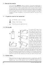
1. 1. Symbols used for the instrument ......................................... 6
1. 2. Tilt handle .............................................................................. 6
1. 3. Safety hints ........................................................................... 6
1. 4. Operating Conditions ............................................................ 7
1. 5. Warranty ............................................................................... 8
1. 6. Maintenance ......................................................................... 8

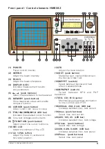
Front panel / Control elements HM6042.................................. 9

2. Set-up of the instrument ......................................................10

2. 1. Safety advice ....................................................................... 10
2. 2. General ................................................................................. 10
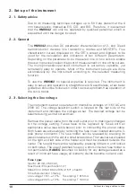
2. 3. Selecting the line voltage ..................................................... 10
2. 4. Screen settings .................................................................... 11
2. 4. 1. Adjusting the trace rotation ............................................. 11
2. 4. 2. Adjusting Y-POS./X-POS. ................................................. 11

3. Performing device tests ........................................................11

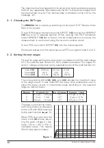
3. 1. Choosing the DUT type ........................................................ 12
3. 2. Setting the test ranges ........................................................ 12
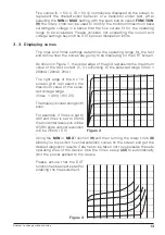
3. 3. Displaying curves ................................................................. 13
3. 4. Measuring device parameters ............................................. 14
3. 5. Using the cursor functions ................................................... 14
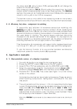
3. 6. Memory function, component matching ............................. 15

4. Application examples............................................................15

4. 1. Characteristic curves of a bipolar transistor ......................... 15
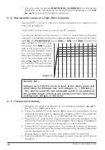
4. 2. Characteristic curves of a field effect transistor .................. 16
4. 3. Component matching .......................................................... 16

Table of contents

St.291097/Bra

Summary of Contents for HM 604-2

Page 1: ...voltage 10 2 4 Screen settings 11 2 4 1 Adjusting the trace rotation 11 2 4 2 Adjusting Y POS X POS 11 3 Performing device tests 11 3 1 Choosing the DUT type 12 3 2 Setting the test ranges 12 3 3 Displaying curves 13 3 4 Measuring device parameters 14 3 5 Using the cursor functions 14 3 6 Memory function component matching 15 4 Application examples 15 4 1 Characteristic curves of a bipolar transis...

Page 2: ...r 91 263 EWG 92 31 CEE Niederspannungsrichtlinie 73 23 EWG ergänzt durch 93 68 EWG Low Voltage Equipment Directive 73 23 EEC amended by 93 68 EEC Directive des equipements basse tension 73 23 CEE amendée par 93 68 CEE Angewendete harmonisierte Normen Harmonized standards applied Normes harmonisées utilisées Sicherheit Safety Sécurité EN 61010 1 1993 IEC CEI 1010 1 1990 A 1 1992 VDE 0411 1994 Übers...

Page 3: ...ruction in the manual for a reduced cable length the maximum cable length of a dataline must be less than 3 meters long If an interface has several connectors only one connector must have a connection to a cable Basically interconnections must have a double screening For IEEE bus purposes the double screened cables HZ72S and HZ72L from HAMEG are suitable 2 Signal cables Basically test leads for si...

Page 4: ...inals for two devices for the comparison of two semiconductors is supplied with the instrument The HM6042 is remarkably easy to operate This makes the instrument also ideally suited for educational use Specifications Reference Temperature 23 C 1 C Measurement Ranges 3 Voltage Ranges Collector Drain Voltages 2V 10V 40V 5 3 Current ranges Collector Drain Currents 2mA 20mA 200mA 5 3 Power Ranges Outp...

Page 5: ...rument If the instrument is set down on the floor after being carried the handle automatically remains in the upright carrying position A In order to place the instrument onto a horizontal surface the handle should be turned to the upper side of the Curve Tracer C For the D position 10 inclination the handle should be turned to the opposite direction of the carrying position until it locks in plac...

Page 6: ...e falls far below the maximum permissible value of 36 pA kg 0 5mR h Whenever it is likely that protection has been impaired the instrument shall be made inoperative and be secured against any unintended operation The protection is likely to be impaired if for example the instrument shows visible damage fails to perform the intended measurements has been subjected to prolonged storage under unfavor...

Page 7: ...he original packing carefully Transport damages and damage due to gross negligence is not covered by warranty In the case of a complaint a label should be attached to the housing of the instrument that describes briefly the faults observed If at the same time the name and telephone number dialing code and telephone or direct number or department designation is stated for possible queries this help...

Page 8: ...10 INT LCD Adjust the contrast of the LCD 11 12 Y POS X POS Adjust the trace in vertical and horizontal position 13 TR Adjust the trace rotation 14 DUT push button Start stop test connect disconnect the Device Under Test 15 BIP FET switch Select between bipolar and field effect transistor diode 16 NPN PNP switch Select between NPN and PNP transistors 17 E S C D B G jacks Mechanical and electrical ...

Page 9: ...e problem free operation of the curve tracer 2 3 Selecting the line voltage The instrument is able to operate with mains line voltages of 115V AC and 230V AC The voltage selection switch is located on the rear side of the instrument and indicates the voltage as set The desired voltage can be selected using a small screwdriver Remove the power cable from the wall outlet prior to making any changes ...

Page 10: ...vice adapter as supplied with each HM6042 is to be mounted to the instrument using the banana jack combination 17 at the front panel of the instrument The terminals are designated as E S Emit ter Source C D Collector Drain and B G Base Gate This adapter is able to carry two DUTs with the help of the instrument s memory function see chapter 4 3 and the device adapter s toggle switch device selectio...

Page 11: ...nals E and C 3 2 Setting the test ranges Through its range settings the instrument is enabled to limit the test voltage UCE UDS and the test current IC ID to predefined values The ranges for current voltage and power can be selected by use of the push buttons for Imax 19 200 mA 20 mA 2 mA Vmax 21 40 V 10 V 2 V Pmax 23 4 0 W 0 4 W 04 W The corresponding LEDs 18 20 and 22 indicate the maximum value ...

Page 12: ...As shown in Figure 1 the upper edge of the grid represents the maximum value of the test current IC ID according to the selected range Imax 200mA 20mA 2mA The right edge of the 8 x 10 screen grid represents the maximum value of the selec ted voltage range Vmax 40V 10V 2V The display is linear along both axes For example if Vmax is set to 40V and Imax is set to 20mA the horizontal resolution will b...

Page 13: ...ighlighted dot indicates the point on a characteristic curve where the actual value is going to be digitized by the instrument After the HM6042 has been powered on the cursor will appear on the third of the five characteristic curves The cursor can be repositioned by using the CURSOR switch 6 or the rotary knob 8 With the CURSOR key 6 the cursor can be moved from one curve to the next To move the ...

Page 14: ...apter Thus the selection of components with respect to the displayed parameter i e IC ID β h11 h22 y21 or y22 is a rather easy and time saving task To quit the memory function or to use another transistor as reference component press the memory button 5 repeatedly 4 Application examples 4 1 Characteristic curves of a bipolar transistor 1 Connect the device to be tested to the appropriate input 2 E...

Page 15: ...t Figure 4 Security hint Voltages up to 50V DC can be present at the device under test when using the following max test voltages VD 40V and VG 10V Anyone using the test equipment needs to be advised of the possible danger and the proper precautions to be taken when working with voltages of this level 4 3 Component matching 1 Measure the desired parameter of the reference transistor 5 the DUT key ...

Reviews: