background image

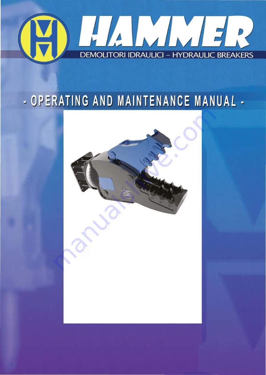
HYDRAULIC ROTARY 

 CRUSHER 

FR SERIES

HAMMER SRL 

Via  Oleifici dell'Italia Meridionale, LOTTO G1 Z.I. 

70056 MOLFETTA (BA) Telefono: +39 080 337 53 17 

Email: info@hammereurope.com Url: www.hammereurope.com


Summary of Contents for FR Series

Page 1: ...HYDRAULIC ROTARY CRUSHER FR SERIES HAMMERSRL Via Oleificidell ItaliaMeridionale LOTTOG1Z I 70056MOLFETTA BA Telefono 390803375317 Email info hammereurope comUrl www hammereurope com...

Page 2: ......

Page 3: ...ibited Publication MIUM_FR_11 2018 00 Publisher HAMMER S r l Printing date 01 02 2018 Attached documentation 1 Intervention request form 2 Spare parts order form 3 Equipment first start up registratio...

Page 4: ...CRUSHER FR SERIES...

Page 5: ...of the equipment 16 2 9 Intended use and limits of use 16 2 10 Technical specifications of HAMMER CRUSHERS 16 2 11 Noise 18 3 SAFETY 19 3 1 Standards and certifications 19 3 2 Safety measures 19 3 2 1...

Page 6: ...Lubrications 32 6 4 Rotation Motor Gearbox 32 6 5 Authorized assistance 33 6 6 Scheduled Maintenance Synoptic Table 33 6 7 Tightening torques of Screws and nuts 34 6 8 Hydraulic pipe dimensions 35 7 D...

Page 7: ...CRUSHER FR SERIES The technical information contained in this manual are not binding HAMMER S r l reserves the right to make any changes necessary to improve the manual at any time...

Page 8: ...S HAMMER S r l Registered Office and Factory Via Oleifici dell Italia Meridionale LOTTO G1 Z I 70056 MOLFETTA BA VAT number 06233290722 Telephone 39 080 337 53 17 Email info hammereurope com Url www h...

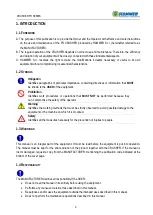
Page 9: ...rformed because they can compromise the safety of the operator Warning Identifies the working methods that must be strictly observed to avoid possible damage to the equipment or the machine on which i...

Page 10: ...of basic standards for determining sound pressure levels at the workplace and in other specific positions 2014 UNI EN ISO 3744 Acoustics Determination of sound power levels and sound energy levels of...

Page 11: ...same conditions as the test itself Prior to delivery the MANUFACTURER will provide the buyer customer with instructions concerning the fundamental principles for use tools controls etc periodic mainte...

Page 12: ...can be read on the plate affixed to the equipment Describe the problem detected Indicate the date by which the intervention is requested1 Stamp and sign the form Send the form by email 1 10 ORDERING S...

Page 13: ...o health that may arise in a dangerous situation INTENDED USE Use of the machine and or equipment in accordance with the information provided in the instructions for use REASONABLY FORESEEABLE INCORRE...

Page 14: ...t in open or excluded protection conditions and to intervene on the mechanical parts to carry out adjustments maintenance and repairs 2 5 OPERATOR QUALIFIED AS HT HYDRAULIC MAINTENANCE TECHNICIAN i e...

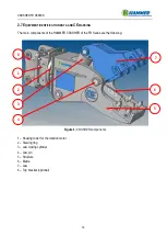
Page 15: ...nents of the HAMMER CRUSHER of the FR Series are the following Figure 1 CRUSHER components 1 Housing tower for the rotation motor 2 Slewing ring 3 Jaw closing cylinder 4 Jaw pin 5 Structure 6 Blade 7...

Page 16: ...ents Figure 2 CE marking In addition to the information contained therein mandatory by law which are Business name and full address of the manufacturer Designation of the equipment type Serial number...

Page 17: ...continuous 360 rotation The CRUSHER must be connected to the excavator s hydraulic circuit which will control its movements 2 9 INTENDED USE AND LIMITS OF USE The HAMMER FR CRUSHER is intended exclusi...

Page 18: ...t perform 17 CRUSHER FR SERIES FR02 FR04 FR07 FR09 FR12 FR15 t 1 5 4 5 10 8 13 11 15 14 18 16 22 kg 220 550 790 950 1450 1700 l min 20 50 50 70 60 100 70 110 110 160 140 200 bar 250 280 300 300 300 30...

Page 19: ...S are not a source of additional noise to that of the excavator Therefore from this point of view follow the instructions provided in the user manual of the latter machine equipped with the FR CRUSHER...

Page 20: ...he MANUFACTURER does not have a direct control over the applications operations inspection lubrication or maintenance of the CRUSHER therefore IT IS THE RESPONSIBILITY OF THE USER to put in place adeq...

Page 21: ...any person not involved in the work in the operating area If necessary stop the activity and do not resume the work until the people are at a safe distance Perform any maintenance operation with the...

Page 22: ...CRUSHER DO NOT modify or remove any part and or component of the CRUSHER equipment DO NOT use the equipment with the protections removed DO NOT remove or inhibit safety devices DO NOT adjust mechanic...

Page 23: ...th the machine in motion Obligation to use overalls Obligation to use hearing protection Obligation to use safety shoes Obligation to use a dust mask Obligation to use a protective helmet Obligation t...

Page 24: ...ground conditions Nature and cause of possible imbalances of the vehicle Maneuvering spaces Visibility conditions and obstacles Before disconnecting the hydraulic pipes check that the circuit is not...

Page 25: ...sure that no persons are within the operating range of the equipment and do not interact manually with this component when assembling disassembling the equipment 2 Rotation Conveying Impact Make sure...

Page 26: ...les Insert the pins in their respective seats and lock them with washers and nuts observe the position of the safety blocks The tightening torques of the nuts depend on their size In this regard see t...

Page 27: ...inity when mounting the CRUSHER on the excavator s arm The CRUSHER extends the excavator s arm so make sure there are no collisions between the parts during its normal use In the event of damage to th...

Page 28: ...hnical specifications for the specific CRUSHER model making sure that they do not have any defects The dimensions of the pipes are shown in the following 6 8 Hydraulic pipe dimensions Please note duri...

Page 29: ...tc Check that the hydraulic connections have been made correctly Most of the drawbacks and failures that may occur are caused by the loosening of the fixing elements and by the presence of leaks which...

Page 30: ...o eliminate the contact and reach a safe distance 4 7 MALFUNCTIONS AND TROUBLESHOOTING ANOMALY CAUSES REMEDIES Locked rotation a Dirt corrosion b Presence of foreign bodies a Clean and dislodge the CR...

Page 31: ...he weight of the crusher can be seen from the data reported in 2 10 Technical specifications of HAMMER CRUSHERS To handle the equipment use the holes provided for this purpose using suitable lifting a...

Page 32: ...of the machine on which the CRUSHER is mounted to prevent the infiltration of foreign bodies and or impurities that could damage important parts of the equipment compromising its correct operation Per...

Page 33: ...rementioned transmission components At the time of the first start up it is advisable to carry out an adequate running in of the gearbox gradually increasing the power of use of the equipment in the f...

Page 34: ...S 2000 HOURS Grease all points indicated in 6 3 Lubrication if working under water Grease points 1 2 3 and 5 indicated in 6 3 Lubrication Screw tightening check Grease point 4 shown in 6 3 Lubrication...

Page 35: ...7992 887 51 210844 1049 32 296163 1480 81 355984 1775 01 M 30 46 84044 465 82 112287 622 73 215748 1206 23 255955 1421 97 359906 2010 38 432476 2402 64 M 33 50 104932 632 53 139746 848 28 269685 1627...

Page 36: ...s for each model of FR CRUSHER the dimensions of the hydraulic connection pipes 35 CRUSHER FR SERIES Model FR 2 FR 4 FR 7 FR 9 FR 12 FR 15 FR 21 FR 26 Rotation hose dimension 1 2 1 2 1 2 1 2 1 2 1 2 1...

Page 37: ...rial hydraulic components etc Empty all components containing oils by collecting the latter in suitable containers Dispose of the various components according to their nature 7 2 DISPOSAL Oils are har...

Page 38: ...Customer _________________________ Date _____________________ CRUSHER FR series MODEL ______ Equipment serial number ___________________ Problem detected Requested intervention date ________ _________...

Page 39: ...omer _________________________ Date _____________________ CRUSHER FR series MODEL _____ Equipment serial number ___________________ The following material is requested Description Quantity NOTES Stamp...

Page 40: ...al static pressure _ _ _ _ _ _ _ _ _ _ bar Return line pressure _ _ _ _ _ _ _ _ _ _ bar Pressure loss in operation_ _ _ _ _ _ _ _ _ _ bar 3 Checks on the equipment Equipment greasing Yes No 4 Training...

Page 41: ......

Page 42: ......

Reviews: