background image

HAMMER

HEAD

CONTACT US

800.626.7835
Contact@HammerHeadClean.com
HammerHeadClean.com

SERVICE

MANUAL

650

RS

Summary of Contents for 650RS

Page 1: ...HAMMERHEAD CONT ACT US 800 626 7835 Contact HammerHeadClean com HammerHeadClean com SERVICE MANUAL 650RS...

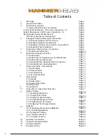
Page 2: ...ch Vacuum Motor 4 4 Squeegee Wheel Adjustment Brush Head Disk Brushes Connections 5 1 Brush Motor Information Brush Head Transport Position 6 1 Brush Switch 6 2 Brush Pressure Adjustment on the Disk M...

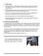
Page 3: ...l safety and accident prevention guidlines The display offers a service indication Upon turning on the key switch a four digit number describing the software version e g 1 0 0 2 appears for about 3 se...

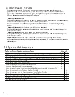
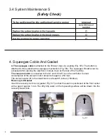
Page 4: ...specified in the operating instructions The operator must be professionally instructed after delivery of the machine by selling dealer System Maintenance I after every 125 hours of operation To be pre...

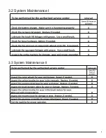
Page 5: ...5 3 2 System Maintenance I 3 3 System Maintenance II...

Page 6: ...er at the rear of the machine The vacuum motor is connected to the A1 at A1 X34 5 6 on the controller Current consumption of the vacuum motor amounts to approx 25A max The vacuum water lift in the clo...

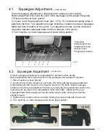
Page 7: ...le type fastener Fig 5 1 Version one 4 2 Squeegee Adjustment Version Two Correct squeegee adjustment is prerequisite for optimal suction results Before adjustment first check the pitch of the squeegee...

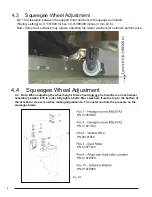
Page 8: ...nce 4 3 Squeegee Wheel Adjustment Fig 5 3 PN 01059530 PN 01071740 PN 00101550 PN 01077810 PN 01079070 PN 01079080 4 4 Note When adjusting the wheel height there should always be 5 washers on each whee...

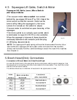
Page 9: ...isconnected Fig 5 4 NOTE The squeegee lift cable spring will need to disconnected from the silver lever before the squeegee lift lever plate can be removed from the machine Access can be made from the...

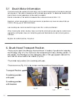
Page 10: ...scroll spring is pressing the carbon brush against the commutator does not contact the guide and that distance to carbon brush guide is sufficient Replace the carbon brushes if required 5 1 Brush Moto...

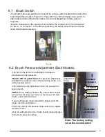
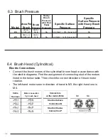
Page 11: ...6 3 The bolt on the left can be adjusted to increase or decrease the brush pressure Models with 19 gallon tanks This pressure adjustment will affect the models in the normal scrubbing mode no extra p...

Page 12: ...nch NA 6 4 Brush Head Cylindrical Electric Connections Connect the brush motors of the cylindrical broom head in accordance with the electric diagrams Find the assignment of connecting stud of the mot...

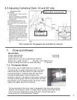
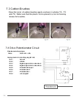
Page 13: ...ee Check the carbon brushes of the drive motor at regular intervals during maintenance Carbon brushes are worn if the scroll spring applying the carbon brushes to the armature is approx 1mm away from...

Page 14: ...ess for brushes Fig 7 2 Fig 7 3 Fig 7 4 Potentiometer Resistance Value 5 875 k Asssignment of connecting plug A1 X4 30 Pin 1 Ground Pin 2 24Volts Pin 3 Digital signal of drive direction 1 Pin 4 Digita...

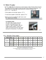
Page 15: ...cated at the front pane of the battery compartment The solenoid valve is electrically connected to the central controller A1 at A1 X11 1 2 See Fig 8 1 approx 0 5 A 8 Water Supply 8 2 Solution Filter T...

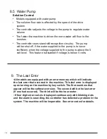
Page 16: ...above the 5 volt level This feature is disabled if voltage is below 5 volts Solution Control 9 The Last Error All models are equipped with an error memory which will indicate the last error that occu...

Page 17: ...17 10 Table of Error Codes...

Page 18: ...18 11 24V 22A Charger 10 1 Operating Instructions 11 1 24V 22A Charger...

Page 19: ...less than 15 volts after 30 minutes 3 The batteries are wired incorrectly reversed polarity 4 The batteries are missing 5 The wrong battery type is installed 6 The selected programming of the charger...

Page 20: ...the Charger Charger Maintenance Points Check the following when servicing the machine The charger unit should be secured by rubber strap The wires going to and from the charger should be secured with...

Page 21: ...it to the side 5 6 Locate the small push button switch on the right side of the charger Located near the rubber strap Plug the charger s A C power cord into the outlet The charger will turn on 9 Push...

Page 22: ...ber 96117197 7 6992 6 Note 3 Do not use other settings on chargers after serial number 96117197 7 6992 6 11 To save the desired mode press and hold the button for more than 5 seconds and release The p...

Page 23: ...tteries can flush the electrolyte out of the battery and shorten its life 4 Fill cells 3 8 to 1 2 of an inch above the separators Do not fill above the fill the marker of the batteries Over filling ca...

Page 24: ...batteries should read 1 265 and will decrease as batteries are discharged until they reach 1 120 This test should be done when batteries are charged and cooled Allow one hour or more to cool It can a...

Page 25: ...ested with the hydrometer Do not attempt to open cell covers or caps Doing so will destroy the battery All the fuses are located on the main control circuit board Part Numbers 00059580 Fuse 125 Amp 80...

Page 26: ...6 58 13 1 Fuse Locations Version 3 Controller 125 Amp Fuse 80 Volts 00059580 5 Amp Fuse 32 Volts 00906120 10 Amp Fuse 32 or 80 Volts 00733630 2 Amp Fuse 32 Volts 00972430 50 Amp Fuse 80 Volts 00902440...

Page 27: ...actor See chapter 16 17 NOTE Always use a coating of high temperature dielectric grease NYOGEL 760G GREASE or equivalent on the motor connectors on the bottom of the controller when replacing the boar...

Page 28: ...28...

Page 29: ...28 17 Contactor Wiring Control Board To batteries and charger Proper wiring of the contactor is critical...

Page 30: ...CONT ACT US 800 626 7835 Contact HammerHeadClean com HammerHeadClean com HAMMERHEAD ENGINEERED SIMPLICITY...

Reviews: