background image

SP500X

Quick Start Guide

SP500X SCAN-PRINTER 

Battery

SP500X*

What’s In The Box

SP500X Parts


For more information and cautions regarding product use, and to request additional product 
support, see the Knowledge Base at: 

www.handheldgroup.com/support-rugged-computers

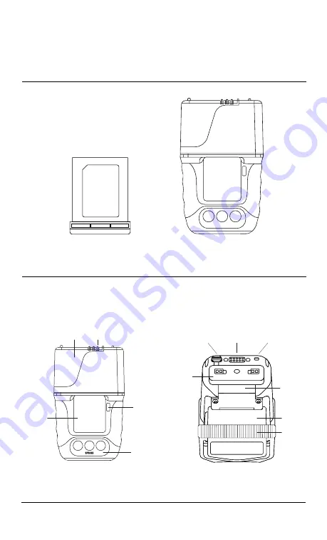
Top

Door

Keypad

User

Label

LCD

Bottom

USB

Connect

Charge

Contacts

Serial Number

under handpad

Battery

Wrist Clip

 holder

Speaker

Output

Fingerstrap

*Includes fingerstrap. Wrist strap purchase separately.

Scanner

Summary of Contents for SP500X

Page 1: ... product use and to request additional product support see the Knowledge Base at www handheldgroup com support rugged computers Top Door Keypad User Label LCD Bottom USB Connect Charge Contacts Serial Number under handpad Battery Wrist Clip holder Speaker Output Fingerstrap Includes fingerstrap Wrist strap purchase separately Scanner ...

Page 2: ...e SP500X will power on Tip To power off the SP500X remove the battery by squeezing the two latches towards one another and pulling the battery out of the SP500X The internal backup battery will keep the SP500X on for up to thirty 30 seconds When the backup battery is exhausted the SP500X will power off Tip To put the SP500X into Sleep Mode press and hold the green power button for ten 10 seconds S...

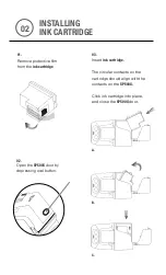
Page 3: ...lm from the ink cartridge 02 Open the SP500X door by depressing oval button 03 Insert ink cartridge The circular contacts on the cartridge should align with the contacts on the SP500X Click ink cartridge into place and close the SP500X door A B C 02 ...

Page 4: ... releasing the button press the same button again and the SP500X will reboot LED Feedback There are two LEDs located at the back of the SP500X on either side The LED colors behavior communicate various feedback Firmware Updating R Solid Red low ink failed print door open low battery Navigate Down Previous Power Enter SP500X Initial Power Up Ready to Print L R Solid Green System Error L R Blinking ...

Page 5: ...rist strap and finger strap Adjust the straps to ensure a secure and comfortable fit Two or three fingers may be used based on what is most comfortable to user Wrist Strap Clip 01 Install the wrist strap by snapping the triangle shaped clip onto the clip holder as shown with the clip s interior angle pointing upwards preinstalled on wrist strap Tips Be careful to not over tighten the straps Remove...

Page 6: ...erver Configuration item Menu SP500X Tasks Server Configuration 02 Select Server Configuration The SP500X scanner light will turn on 03 Aim the scanner light at the configuration barcode The light will turn off once the barcode is read Upon connection to the access point the LCD will display SUCCESS 04 The SP500X will reboot to update the server and network settings 05 The SP500X is now ready to u...

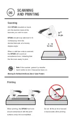
Page 7: ...ned 5 10 inches away from the desired barcode at a twenty degree angle When a valid barcode is scanned the SP500X will sound an acceptance tone indicating that the device is ready to print 20 Angle 5 10 Inches When printing the SP500X front end should remain level with the print surface until print is completed Do not tilt the printer forward or backwards while printing 06 Warning Do No Stare Into...

Page 8: ...are properly configured Foam hand pad is attached using velcro To remove or replace grasp pad and gently pull away from the SP500X To remove or replace finger strap use moderate pressure to release each clip by pressing or pulling clip towards the SP500X To remove or replace wrist strap use moderate pressure to release or press in each side one at a time See also section 04 for orientation details...

Page 9: ...r It is the responsibility of the user to correct any interference caused by such unauthorized modification substitution or attachment The manufacturer and its authorized resellers or distributors will assume no liability for any damage or violation of government regulations arising from failure to comply with these guidelines This device must not be co located or operated in conjunction with any ...

Page 10: ...ice has been tested and meets the FCC IC RF exposure guidelines when tested with the device operating conditions Déclaration de la FCC d Industrie Canada sur l exposition aux radiofréquences La norme régissant l exposition des appareils sans fil aux radiofréquences emploie une unité de mesure dénommée Taux d absorption spécifique ou TAS La FCC et Industrie Canada ont défini la même limite de TAS 1...

Page 11: ...el utilisant les bandes 5 250 5 350 MHz 5 470 5 725 MHz et 5 725 5 825 MHz conformément à la limite p i r e maximale permise afférent aux périphériques RSS 247 En outre les utilisateurs doivent prendre garde au fait que les radars de grande puissance sont considérés comme des utilisateurs principaux ce qui signifie qu ils sont prioritaires des bandes 5 250 5 350 MHz et 5 650 5 850 MHz et qu ils po...

Reviews: