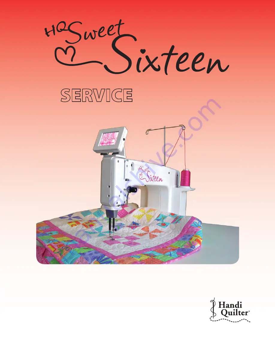
Handiquilter HQ Sweet Sixteen, Service Manual
Discover the versatile handi quilter HQ Sweet Sixteen and unleash your quilting creativity! Seamlessly transition from free-motion quilting to precision stitching with this exceptional machine. Access the comprehensive User Manual, available for free download at 88.208.23.73:8080. Master your quilting skills and explore endless possibilities with this remarkable product.
Share
Download

Reviews:
No comments
Related manuals for HQ Sweet Sixteen

SC-330 RS
Brand: SCANMASKIN Pages: 60

CONTOUR 350 DELUXE
Brand: H. Winter Pages: 23
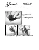
Bobbin Winder
Brand: Gammill Pages: 3

MB-7e
Brand: Janome Pages: 115

3574-2/02
Brand: Pfaff Pages: 90

BindMate
Brand: GBC Pages: 2

567 CLASSIC
Brand: Dürkopp Adler Pages: 80

9082317010
Brand: Nilfisk-Advance Pages: 39

SD-10
Brand: BRONDI Pages: 32

AMS-210E Series
Brand: JUKI Pages: 243

ASN-690
Brand: JUKI Pages: 50

DLD-5430N
Brand: JUKI Pages: 72

Advenger 2800ST
Brand: Nilfisk-Advance Pages: 104

LK-1850 Series
Brand: JUKI Pages: 2

LH-3528A
Brand: JUKI Pages: 8

LH-3128
Brand: JUKI Pages: 10

HZL35Z-UL5
Brand: JUKI Pages: 76

Crescendo Quilting & Sewing Machine
Brand: Baby Lock Pages: 2


