background image

www.modellmarkt24.ch

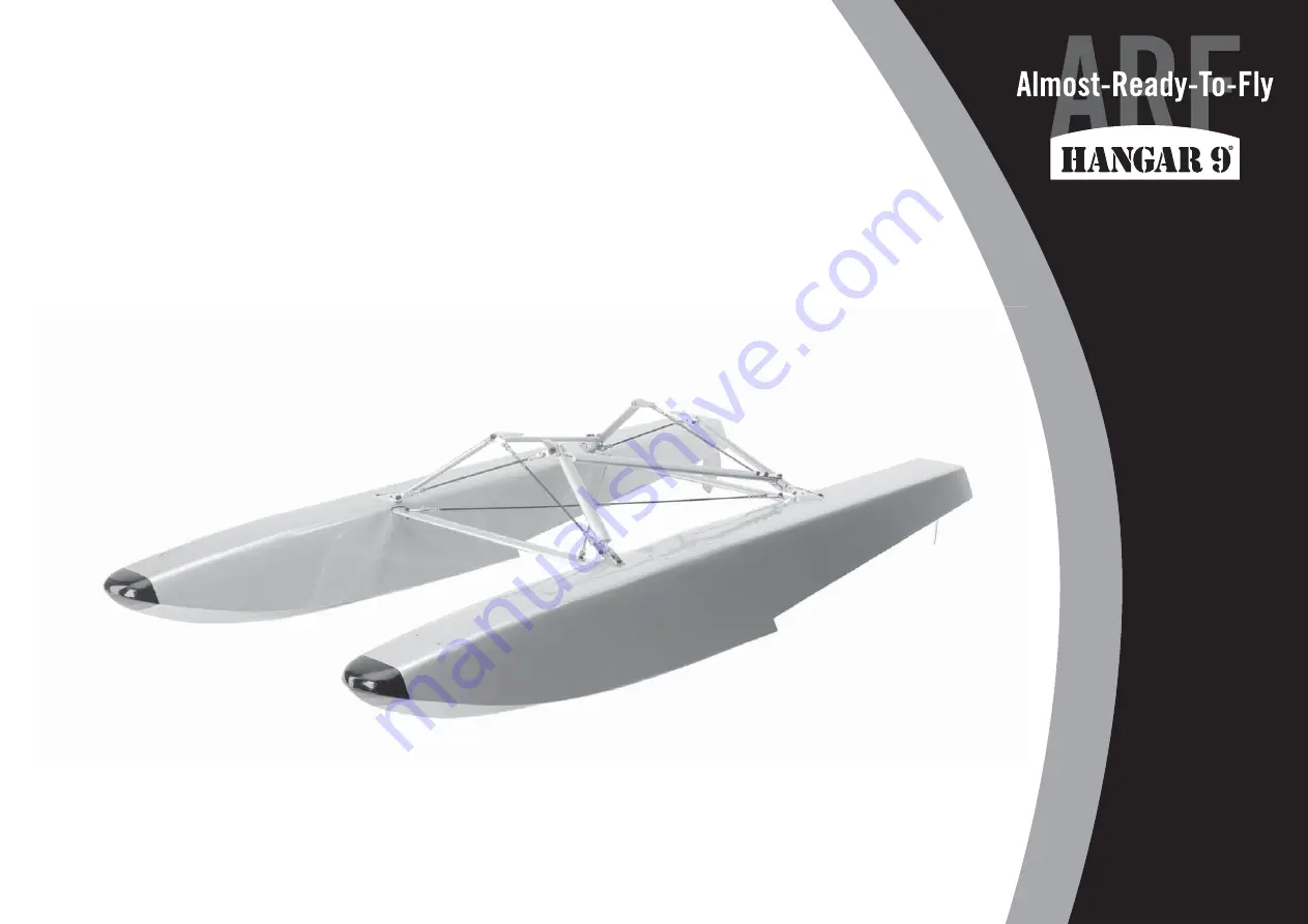
1/5-Scale Floats

Instruction Manual

Bedienungsanleitung

Manuel d’utilisation

Manuale di Istruzioni

www.modellmarkt24.ch

Summary of Contents for HAN6030

Page 1: ...www modellmarkt24 ch 1 5 Scale Floats Instruction Manual Bedienungsanleitung Manuel d utilisation Manuale di Istruzioni www modellmarkt24 ch ...

Page 2: ...GRANDI SPECIFICATIONS SPEZIFIKATIONEN SPÉCIFICATIONS SPECIFICHE A 227 32 inches 564mm B 421 16 inches 1067mm C 67 8 inches 175mm D 1615 32 inches 418mm E 827 32 inches 225mm F 115 16 inches 49mm G 5 8 inches 15 5mm H 21 4 inches 57mm I 31 4 inches 83mm A C D E F G H I B 1 3 4 6 6 5 2 www modellmarkt24 ch ...

Page 3: ...tension 12 inch 300mm Spektrum Servokabelverlängerung 300mm Rallonge servo standard 300mm Prolunga standard per servo 300mm REQUIRED ADHESIVES ERFORDERLICHE KLEBSTOFFE TYPES DE COLLES ADESIVI NECESSARI PAAPT09 Thin CA Sekundenkleber dünnflüssig Colle cyano fine Sottile CA REQUIRED TOOLS BENÖTIGTES WERKZEUG OUTILS REQUIS ATTREZZI NECESSARI Clear tape klares Klebeband Ruban adhésif transparent Nastro ...

Page 4: ...mpatibility questions exist please refer to the product instructions component instructions or contact the appropriate Horizon Hobby office Flight Fly only in open areas to ensure safety It is recommended flying be done at radio control flying fields Consult local ordinances before choosing a flying location Propeller Keep loose items that can become entangled in the propeller away from the prop This i...

Page 5: ...rt für das betreffende Produkt Spezielle Bedeutungen Die folgenden Begriffe werden in der gesamten Produktliteratur verwendet um auf unterschiedlich hohe Gefahrenrisiken beim Betrieb dieses Produkts hinzuweisen HINWEIS Wenn diese Verfahren nicht korrekt befolgt werden können sich möglicherweise Sachschäden UND geringe oder keine Gefahr von Verletzungen ergeben ACHTUNG Wenn diese Verfahren nicht ko...

Page 6: ...izonhobby com et cliquez sur l onglet de support de ce produit Signification de certains termes spécifiques Les termes suivants sont utilisés dans l ensemble du manuel pour indiquer différents niveaux de danger lors de l utilisation de ce produit REMARQUE Procédures qui si elles ne sont pas suivies correctement peuvent entraîner des dégâts matériels ET éventuellement un faible risque de blessures AT...

Page 7: ...è opportuno far riferimento alle istruzioni relative al prodotto o ai componenti oppure rivolgersi al reparto Horizon Hobby di competenza Volo Per sicurezza volare solo in aree molto ampie Meglio se in campi volo autorizzati per modellismo Consultare le ordinanze locali prima di scegliere luogo dove volare Elica Tenere gli oggetti liberi vestiti penne cacciaviti ecc lontano dall elica prima che vi...

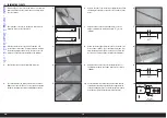
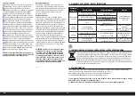
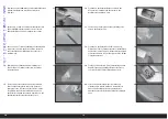
Page 8: ...he float Use a pencil to mark the locations for the servo mounting screws 5 Remove the servo Use a pin vise and 5 64 inch 2mm drill bit to drill the holes for the servo mounting screws 7 Place 2 to 3 drops of thin CA in each hole to harden the surrounding wood Allow the CA to fully cure before proceeding 6 7 8 9 10 9 Use a pin vise and 5 64 inch 2mm drill bit to enlarge the hole in the arm that is ...

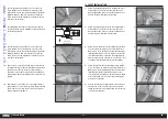
Page 9: ...cure before proceeding 16 17 18 19 20 16 Slide the pushrod wire into the pushrod tube in the rear of the float Guide the wire through the pushrod connector at the servo 18 Slide the rudder through the bracket and horn Align the flat on the rudder with the screw in the horn Remove the screw and apply a drop of thread lock on the screw then use it and a 2 Phillips screwdriver to secure the rudder by t...

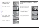
Page 10: ... 5 8 9 8 inch 206mm 1 8 10 Nylon locknut Diagonal brace Nylon washer Nylon washer Cross brace wire Rear Strut to Float Attachment Front M3 x 25 Socket Head Cap Screw 6 Remove the end of one of the longer support braces Slide the tubing onto the brace then place the end back on the brace 7 Adjust the ends on the longer support braces so the distance between the screws measures 171 2 inches 445mm 8 ...

Page 11: ...ket head cap screw M3 washer and M3 lock nut Use a 2 5mm hex wrench and 5 5mm nut driver to tighten the hardware 1 2 3 4 5 1 Attach the mounting bracket to the rear diagonal brace using an M3 x 15 socket head cap screw two nylon washers and an M3 lock nut Leave the hardware loose until the floats are attached to the fuselage 2 Attach the mounting bracket to the front diagonal brace using an M3 x 15...

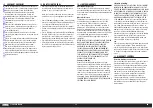
Page 12: ...ng silicone adhesive Allow the adhesive to fully cure before proceeding 6 7 8 9 10 When installing the floats on your model you must check the Center of Gravity before flying The installation of the floats will change the Center of Gravity and as such could cause some undesirable flight characteristics or even possibly the loss of your aircraft Refer to your original manual for the specifications regar...

Page 13: ...red for all warranty claims SERVICE OR REPLACEMENT AS PROVIDED UNDER THIS WARRANTY IS THE PURCHASER S SOLE AND EXCLUSIVE REMEDY Limitation of Liability HORIZON SHALL NOT BE LIABLE FOR SPECIAL INDIRECT INCIDENTAL OR CONSEQUENTIAL DAMAGES LOSS OF PROFITS OR PRODUCTION OR COMMERCIAL LOSS IN ANY WAY REGARDLESS OF WHETHER SUCH CLAIM IS BASED IN CONTRACT WARRANTY TORT NEGLIGENCE STRICT LIABILITY OR ANY ...

Page 14: ...re agreeing to Horizon s Terms and Conditions found on our website http www horizonhobby com content _service center_render service center ATTENTION Horizon service is limited to Product compliant in the country of use and ownership If received a non compliant Product will not be serviced Further the sender will be responsible for arranging return shipment of the un serviced Product through a carr...

Page 15: ...arkieren Sie mit einem Stift die Positionen der Servoschraublöcher 5 Nehmen Sie das Servo heraus Bohren Sie mit einem 2mm Bohrer die Löcher für die Servoschraublöcher 7 Geben Sie 2 bis 3 Tropfen dünnflüssigen Sekundenkleber in jedes Loch um das umgebende Holz zu härten Lassen Sie den Sekundenkleber vollständig trocknen bevor Sie weiter arbeiten 6 7 8 9 10 9 Vergrößern Sie das Loch was sich 12mm von...

Page 16: ...Sekundenkleber in jedes der Löcher um das Holz zu härten Lassen Sie den Sekundenkleber vollständig trocknen bevor Sie weitermachen 16 17 18 19 20 16 Schieben Sie das Rudergestänge von hinten in das Röhrchen im Schwimmer und dann weiter in den Gestängeschanschluss am Servo 18 Schieben Sie das Ruder in den Halter und Horn ein Richten Sie die flache Stelle passend zur Schrauböffnung aus Geben Sie eine...

Page 17: ... 7 17 inch 445mm 1 5 8 9 8 inch 206mm 1 8 10 Nylon Stopmutter Diagonal Halter Nylon Unterlegscheibe Nylon Unterlegscheibe Kreuzspanndraht Hinterer Strebenhalter Vorne M3 x 25 Sechskantschraube 6 Drehen Sie das Endstück der längeren Verspannungen ab Schieben Sie den Schlauch auf die Verspannung und drehen das Endstück wieder auf 7 Justieren Sie die Endstücke der beiden Halter so dass die Länge wie ...

Page 18: ...Halters mit einer M3 x 12 Inbusschraube einer M3 Unterlegscheibe und M3 Stopmutter Verwenden Sie einen 2 5 mm Inbusschlüssel und 5 5mm Steckschlüssel 1 2 3 4 5 1 Montieren Sie den hinteren diagonalen Halter mit einer M3 x 15 Sechskantschraube zwei Nylon Unterlegscheiben und einer einer M3 Stopmutter Ziehen Sie die Schrauben noch nicht ganz fest an bis die Schwimmer am Rumpf montiert werden 2 Monti...

Page 19: ...seite Sichern Sie das Y Kabel oder die Verlängerung in der Öffnung mit Silikonkleber Lassen Sie den Kleber vollständig trocknen bevor Sie weitermachen 6 7 8 9 10 Nach der Montage der Schwimmer am Modell muß vor dem Fliegen der Schwerpunkt geprüft werden da sich dieser geändert hat Änderungen im Schwerpunkt können die Flugeigenschaften erheblich verändern und im schlimmsten Fall zum Absturz führen ...

Page 20: ...hang mit einem Vertrag der Garantie oder der Gewährleistung erhoben werden Horizon wird darüber hinaus keine Ansprüche aus einem Garantiefall akzeptieren die über den individuellen Wert des Produktes hinaus gehen Horizon hat keinen Einfluss auf den Einbau die Verwendung oder die Wartung des Produktes oder etwaiger Produktkombinationen die vom Käufer gewählt werden Horizon übernimmt keine Garantie u...

Page 21: ...alb kontaktieren Sie in einem solchen Fall den Händler der sich mit Horizon kurz schließen wird um eine sachgerechte Entscheidung zu fällen die Ihnen schnellst möglich hilft Wartung und Reparatur Muss Ihr Produkt gewartet oder repariert werden wenden Sie sich entweder an Ihren Fachhändler oder direkt an Horizon Rücksendungen Reparaturen werden nur mit einer von Horizon vergebenen RMA Nummer bearbe...

Page 22: ... marquer l emplacement des vis de montage du servo 5 Retirez le servo Utilisez un porte foret et un foret de 2mm pour percer les trous pour les vis de montage du servo 7 Mettez 2 à 3 gouttes de colle CA dans chaque trou afin de durcir le bois autour Laissez la colle sécher avant de continuer 6 7 8 9 10 9 Utilisez un porte foret et un foret de 2mm pour élargir le trou dans le palonnier qui se situe ...

Page 23: ...6 17 18 19 20 16 Passez le câble dans le tube de tringlerie à l arrière du flotteur Passez le câble dans le connecteur tringlerie au servo 18 Glissez le gouvernail dans le support et le guignol Alignez le plat du gouvernail avec la vis du guignol Retirez la vis et appliquez une goutte de frein filet sur la vis puis utilisez la ainsi qu un tournevis cruciforme 2 pour fixer le gouvernail en serrant la ...

Page 24: ...6 7 17 inch 445mm 1 5 8 9 8 inch 206mm 1 8 10 Contre écrou en nylon Tirant diagonal Rondelle en nylon Rondelle en nylon Traverse Fixation du hauban arrière sur le flotteur Avant Vis taraudeuse M3 x 25 6 Retirez l extrémité de l une des entretoises de support longues Passez le tube sur l entretoise puis remettez l extrémité de l entretoise en place 7 Réglez les extrémités des entretoises de support ...

Page 25: ...agonal à l aide d une vis BTR M3 x 12 d une rondelle M3 et d un contre écrou M3 Utilisez une clé hexagonale 2 5mm et un tourne écrou 5 5mm pour serrer la visserie 1 2 3 4 5 1 Attachez le support de montage sur le tirant diagonal arrière à l aide d une vis BTR M3 x 15 de deux rondelles en nylon et d un contre écrou M3 Laissez la visserie desserrée jusqu à ce que vous installiez les flotteurs sur le ...

Page 26: ...ant de la colle silicone Laissez la colle sécher complètement avant de continuer 6 7 8 9 10 Lorsque vous installez des flotteurs sur votre modèle vous devez vérifier le centre de gravité avant de voler L installation de flotteurs va modifier le centre de gravité et donc entrainer des caractéristiques de vol indésirables ou même la perte de votre avion Consultez votre manuel original pour obtenir les d...

Page 27: ...tilisant et en montant le produit l acheteur accepte sans restriction ni réserve toutes les dispositions relatives à la garantie figurant dans le présent document Si vous n êtes pas prêt en tant qu acheteur à accepter ces dispositions en relation avec l utilisation du produit nous vous demandons de restituer au vendeur le produit complet non utilisé et dans son emballage d origine Indications relat...

Page 28: ...nt à Horizon Emballez le produit soigneusement Veuillez noter que le carton d emballage d origine ne suffit pas en règle générale à protéger le produit des dégâts pouvant survenir pendant le transport Faites appel à un service de messagerie proposant une fonction de suivi et une assurance puisque Horizon ne prend aucune responsabilité pour l expédition du produit jusqu à sa réception acceptée Veuil...

Page 29: ...una matita segnare la posizione delle viti di montaggio 5 Togliere il servo e forare con una punta da 2mm per le viti di fissaggio 7 Mettere in ciascun foro 2 o 3 gocce di colla CA liquida per indurire la filettatura nel legno creata prima Prima di procedere attendere che la colla asciughi completamente 6 7 8 9 10 9 Con una punta da 2mm allargare il foro sulla squadretta del servo che si trova a 12m...

Page 30: ...re il filo del rinvio nel tubo predisposto nella parte posteriore del galleggiante Far passare il filo attraverso il morsetto del rinvio per arrivare al servo 18 Far scorrere il timone attraverso il supporto e la squadretta Allineare la parte piatta sull asse del timone alla vite sulla squadretta Togliere la vite e mettere una goccia di frenafiletti su di essa e poi stringerla sulla parte piatta per ...

Page 31: ...lano i tiranti 6 7 17 inch 445mm 1 5 8 9 8 inch 206mm 1 8 10 Dado autobloccante Tirante diagonale Rondella nylon Rondella nylon Filo braccio trasversale Fissaggio montante posteriore all attacco del galleggiante Davanti Vite a brugola M3 x 25 6 Togliere il terminale da uno dei supporti più lunghi Far scorrere il tubo sul supporto poi mettere di nuovo il terminale al supporto 7 Regolare le estremit...

Page 32: ...re del braccio laterale al tirante diagonale con una vite a brugola M3x12 una rondella e un dado autobloccante M3 Stringere il tutto con una chiavetta esagonale da 2 5mm e una chiave aperta da 5 5mm 1 2 3 4 5 1 Fissare la staffa di montaggio al tirante diagonale posteriore con una vite a brugola M3x15 due rondelle in nylon e un dado autobloccante M3 Non stringere le viti finché i galleggianti non v...

Page 33: ... la prolunga a Y o la prolunga nel foro Prima di procedere attendere che l adesivo si asciughi completamente 6 7 8 9 10 Quando si installano i galleggianti sul proprio modello bisogna sempre controllare il baricentro prima di andare in volo L installazione dei galleggianti cambierà la posizione del baricentro e quindi potrebbe causare degli assetti di volo indesiderati o addirittura far precipitar...

Page 34: ...ranzia citate in questa sede Qualora l utente non fosse pronto ad assumersi tale responsabilità associata all uso del prodotto si suggerisce di restituire il prodotto intatto mai usato e immediatamente presso il venditore Indicazioni di sicurezza Questo è un prodotto sofisticato di hobbistica e non è un giocattolo Esso deve essere manipolato con cautela con giudizio e richiede delle conoscenze basi...

Page 35: ...ettamente ad Horizon Il prodotto deve essere imballato con cura Bisogna far notare che i box originali solitamente non sono adatti per effettuare una spedizione senza subire alcun danno Bisogna effettuare una spedizione via corriere che fornisce una tracciabilità e un assicurazione in quanto Horizon non si assume alcuna responsabilità in relazione alla spedizione del prodotto Inserire il prodotto ...

Page 36: ...www modellmarkt24 ch 36 www modellmarkt24 ch ...

Page 37: ...www modellmarkt24 ch 37 Carbon Cub 15cc www modellmarkt24 ch ...

Page 38: ...www modellmarkt24 ch 38 www modellmarkt24 ch ...

Page 39: ...HAN Carbon Cub montieren wollen Veuillez utiliser ce modèle si vous installez les flotteurs 1 5 sur des modèles autres que HAN Carbon Cub Usare questo template quando andrete ad installare i galleggianti in scala 1 5 in un modello che non sia l Hangar 9 Carbon Cub Front Vorne Avant Davanti Float Step Location Trittstufe Schwimmer Emplacement de la marche du flotteur Posizione gradino del galleggiant...

Page 40: ...y logo are registered trademarks of Horizon Hobby LLC The Spektrum trademark is used with permission of Bachmann Industries Inc All other trademarks service marks and logos are the property of their respective owners Patents pending 47077 Created 01 2016 www modellmarkt24 ch ...

Reviews: