Hantek DPO6000 Series, Product Manual
The Hantek DPO6000 Series offers cutting-edge technology and advanced features for professionals in need of precise measurements. With its comprehensive user manual available for download absolutely free, you can easily unleash the full potential of this product from 88.208.23.73:8080, allowing you to make accurate measurements with ease.
Share
Download


Reviews:
No comments
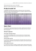
Related manuals for DPO6000 Series

SACE Tmax XT Series
Brand: ABB Pages: 11

963
Brand: MacDon Pages: 89

903
Brand: Yates Pages: 2

HF
Brand: JAC Pages: 100

KP312
Brand: Makita Pages: 8

190
Brand: VECTECH Pages: 5

CLASSIC
Brand: Eastern Jungle Gym Pages: 17

VCL Series
Brand: Vahle Pages: 96

BTL PA0400 Series
Brand: Balluff Pages: 22

Micropulse BTL5 Series
Brand: Balluff Pages: 12

BNI IOW-560-W01-K022
Brand: Balluff Pages: 32

MK5
Brand: Baltic Pages: 68

150N
Brand: Baltic Pages: 68

Max Charge MC-612
Brand: Balmar Pages: 12

BTL PA0400 Series
Brand: Balluff Pages: 204

NI VISION PCI-8254R
Brand: National Instruments Pages: 13

NI VISION PCI-8254R
Brand: National Instruments Pages: 16

NI-9230
Brand: National Instruments Pages: 10


