background image


hanwell.com


GD6063 

MS1000 Control System 


Installation Guide 

Summary of Contents for MS1000

Page 1: ...hanwell com GD6063 MS1000 Control System Installation Guide...

Page 2: ...Intentionally Left Blank...

Page 3: ...System Installation Guide hanwell com Page 1 of 31 GD6063 1 Document History Document Number GD6063 Issue No Issue Date Changes By 1 26 October 2018 Changes to take account of introduction of EMS and...

Page 4: ...ts 13 4 1 Firmware 13 4 2 Software 13 4 2 1 New Systems 13 4 2 2 Existing Systems 13 5 Pre Commissioning 14 6 MS1000 Output Card ID Number 15 6 1 ID Number 15 6 1 1 Setting the ID Number 15 7 Connecti...

Page 5: ...Code N051 22 8 1 4 MS1000 Output Card Case 23 8 2 Allowable Temperature and Humidity Ranges 23 9 Hanwell MS1000 System Fault Checking 24 9 1 Signals are not being received on any channels 24 9 2 Signa...

Page 6: ...t are compatible with the Hanwell Environmental Monitoring System EMS software Typical applications could include Interfacing radio sensors to a Building Management System BMS Conservation heating sys...

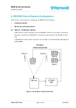
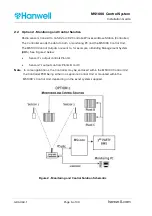
Page 7: ...one Solution Monitoring and Control Solution 2 1 Option 1 Standalone Solution Radio sensors transmit directly back to the MS1000 Control Unit via either a standalone Receiver connected to the MS1000 o...

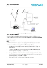
Page 8: ...Control Unit The MS1000 Control Outputs are sent to for example a Building Management System BMS See Figure 2 below Sensor 1 s output controls Plant A Sensor 2 s output controls Plants B and C Note In...

Page 9: ...als from Hanwell radio and wired sensors and is designed for continuous monitoring of an entire system Received data is then logged and stored pending transfer to a PC for analysis and archival storag...

Page 10: ...recent data and downloads the data according to user defined logging periods to the server or operating PC from where software users can view live and historic data produce out of specification and s...

Page 11: ...systems The presence and number of any alarms on the system being controlled The input signal received directly from the sensors or via a Controller is passed from the first Output Card added to each...

Page 12: ...ither a larger MS1000 Control Unit or multiple Control Units connected together can supply additional outputs See Section 8 1 MS1000 Enclosure for case options Two card types signal output are availab...

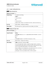
Page 13: ...logue Output Card Number of Outputs 4 Output Options Either A Voltage between 2 SOME REFS STATE 0 HERE and 10V 1mA Or A Current between 0 and 20mA compliance 12V Pin Out See Table 6 Output Card Wiring...

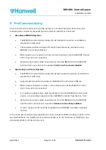
Page 14: ...RS User Requirement Specification detailing the output requirements for the system These will then be programmed into the MS1000 Firmware The URS should include the following information Control Strat...

Page 15: ...process to set up the MS1000 Monitoring and Control Systems and for monitoring data via the CR3 SR2 Controller during normal operation 4 2 1 New Systems New systems will be supplied with the most rec...

Page 16: ...rly labelled Monitoring and Control Systems The MS1000 Control Unit s case s should be mounted in position and drilled as required for cable entry Output Cards should be mounted on the MS1000 Control...

Page 17: ...ed to be changed on site 6 1 1 Setting the ID Number The ID number is set using a set of 8 DIP switches on the PCB These work in binary fashion being either ON or OFF as shown in Table 1 ID Number bel...

Page 18: ...switched feed fused at 3 Amps This is connected via a DIN rail mounted power supply labelled with live neutral and earth as shown in Figure 6 Power Supply Connections 12V is generated internally to po...

Page 19: ...ied cable consists of a 2 metre 4 core cable with a moulded mini DIN plug and a free end The Customer supplied cable should be to the specifications outlined below in Table 5 Wiring Specifications 7 3...

Page 20: ...s a result it is important to ensure that the correct connections are made between the CR3 SR2 Controller and the MS1000 Control Unit via the Hanwell supplied cable with a moulded mini DIN plug the Ju...

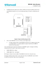
Page 21: ...nector mounted on the DIN rail as shown in Table 3 below Pin Signal Power Line Description 1 TX RS485 Tx 2 TX RS485 Tx 3 12V Power 12V 7 GND Power 0V Table 3 8 Test and confirm correct operation follo...

Page 22: ...4 Customer Supplied Wiring Required Specifications Minimum Specification Brand Rex HF57502 or UL Style 2464 or equivalent for example RS Stock No 362 184 Note Cat5e networking cable can also be used a...

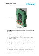
Page 23: ...should be made to the appropriate Output Card terminals as specified in Table 6 and Figure 8 OUTPUT CARD CHANNEL OUTPUT PINS 1 2 3 4 RELAY 1 2 Common DO NOT USE Normally Open NO NC 3 4 Common Normally...

Page 24: ...to carry them Appropriate wall mounting options should be discussed prior to supply and installation Cable glands are provided on the lower panel to allow entry of wiring from connected equipment e g...

Page 25: ...Protection Rating IP66 to EN6529 10 91 complies with NEMA12 8 1 4 MS1000 Output Card Case The MS1000 Output Card is fitted into a DIN rail mountable Case Case Height 112mm Case Width 100mm Case Depth...

Page 26: ...trol Unit OFF 3 Wait until the three LEDs on the CR 1 go off 4 Switch the CR 1 back on It should then display its program information and start receiving data The links between the MS1000 and the 3rd...

Page 27: ...on some channels Possible Causes Action to Take Incorrect or loose wiring between the MS1000 and the 3rd party system Check the wiring on all faulty sensors Low batteries in some sensors Check the ba...

Page 28: ...ion to Take Incorrect wiring between the MS1000 and the 3rd party system Check the wiring on all faulty sensors Incorrect scaling on the 3rd party system s software Check the scale used on the 3rd par...

Page 29: ...S must be drawn up and supplied to Hanwell Instruments before the MS1000 system is commissioned This document details the custom operation of the supplied Hanwell MS1000 system The custom operation is...

Page 30: ...com 11 Contact Information Hanwell Solutions Ltd Head Office Pendle House Jubilee Road Letchworth Hertfordshire SG6 1SP United Kingdom Switchboard 44 0 1462 688070 Technical Support 44 0 1462 688078...

Page 31: ...ber Serial Number Test Telemetry ID Receiver frequency Customer Name Test Ins Ref Test Description Pass Fail Y N Comments All connectors and cables tight All Earth leads connected and tight Receiver M...

Page 32: ...MS1000 Control System Installation Guide GD6063 1 Page 30 of 30 hanwell com Comments...

Page 33: ...Intentionally Blank...

Page 34: ......

Reviews: