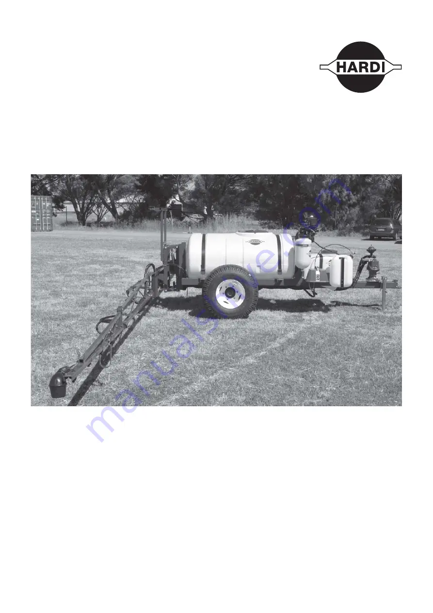
background image

Grassland 1200 


Original

Instruction book 

67028904-100 - Version 1.00
GB - 07.2016

www.hardi.com.au

Summary of Contents for Grassland 1200

Page 1: ...Grassland 1200 Original Instruction book 67028904 100 Version 1 00 GB 07 2016 www hardi com au ...

Page 2: ... to the best of our belief correct at the time of printing As it is HARDI AUSTRALIA policy permanently to improve our products we reserve the right to make changes in design features accessories specifications and maintenance instructions at any time and without notice HARDI AUSTRALIA is without any obligation in relation to implements purchased before or after such changes HARDI AUSTRALIA cannot ...

Page 3: ...19 Residual Energy 20 Possible Dangers 20 Service and Maintenance Work 21 Statutory Inspection 21 Preventive Measures 21 Design Changes 22 Operator Limitations 22 Spare Parts Wear Parts and Aids 22 Cleaning and Disposal 23 Environmental Protection 23 Workstation 24 Intended Place for Operator 24 Risks of Non Compliance 24 If the Safety Information is Ignored 25 Possible Risks and Dangers 25 Safety...

Page 4: ...stem 51 Filling Washing Location Requirements 51 Filling of Water 51 Filling Through Tank Lid 52 Filtered Fill Optional 52 Filling of Rinsing Tank 52 Filling of Clean Water Tank 53 Safety Precautions Crop Protection Chemicals 54 Filling Liquid Chemicals by using HARDI TurboFiller optional 55 Filling Powder Chemicals by using HARDI TurboFiller optional 56 Operating the Control Unit While Spraying S...

Page 5: ...50 Hours Service Hydraulic Circuit 73 250 Hours Service Hoses and Tubes 74 Occasional Maintenance 75 Safety Valve Activation 75 Pump Valves and Diaphragms Renewal 76 Cone Check Renewal for Pressure Regulation Valve 77 Cone Check Renewal for EVC Distribution Valve 77 Nozzle Tubes and Fittings 78 Adjustment of 3 Way Valve 78 Readjustment of Boom 78 Off Season Storage 79 General Info 79 Before Storag...

Page 6: ...6 ...

Page 7: ...adingit please contact the manufacturer or your HARDI dealer A worker is hereinafter called an operator An operator is a person who installs operates configures adjusts maintains cleans repairs transports or moves the sprayer Use of Work Equipment Throughout the lifetime of the sprayer the owner shall take every measure to ensure the safety of the sprayer and its equipment made available to operat...

Page 8: ...quipment has been installed correctly and is operating properly 2 In order to ensure that health and safety conditions are maintained and that deterioration liable to result in dangerous situations can be detected and remedied in good time the employer shall ensure that work equipment exposed to conditions causing such deterioration is subject to 3 The results of inspections shall be recorded and ...

Page 9: ... them inasmuch as they affect work equipment situated in their immediate work area or site even if they do not use such equipment directly 3 The information and the written instructions shall be comprehensible to the workers concerned Article 9 Training of workers Without prejudice to Article 12 of Directive 89 391 EEC the employer shall take the measures necessary to ensure that a the use of work...

Page 10: ...al by authorized persons The results of inspection testing shall be recorded and kept Health Issues Ergonomics and occupational health aspects shall be taken fully into account by the owner Obligationsof the Operator Before starting work the operator or anyone incharge of working with on the sprayer is obliged to comply with the basic workplace safety instructions and accident prevention regulatio...

Page 11: ... following causes Improper use of the sprayer Improper installation commissioning operation and maintenance of the sprayer Operation of the sprayer with defective safety equipment or improperly attached or non functioningsafety equipment Non compliance with the instructions in the instruction manual regarding commissioning operation and maintenance Unauthorized design changes to the sprayer Insuff...

Page 12: ...provided by the manufacturer of the plant protection product to be used such as This Instruction Book must always be kept together with the sprayer must always be easily accessible for the operator Chemical resistantgloves Chemical resistant and disposable overalls Water resistantfootwear Face shield Breathing protection Eye protection Head protection Skin protection products ...

Page 13: ...erious physical injury if the instruction is not followed This symbol means WARNING Be alert as your safety can be involved The WARNING symbol indicates a medium risk for immediate death or serious injury if the instruction is not followed μ This symbol means ATTENTION This indicates an obligation to special behaviour or an activity required for proper sprayerhandling Thisinstruction willhelpyouto...

Page 14: ...mations about chemical preparation before handling the machine Observe instructions and safety rules when operating Service Carefully read the Instruction Book before handling the machine Observe instructions and safety rules when operating Service Turn off the engine and remove ignition key before performing maintenance or repair Service Tightento thetorqueaccordingto instruction book Risk of dea...

Page 15: ...Risk of falling off Do not ride on platform or ladder Risk of sprayer tipping over Be aware when disconnecting the sprayer Grapping area Manual handling of the boom etc Not for drinking This water must never be used for drinking Not for drinking This water must never be used for drinking Lifting point Lifting point Load index Max permitted load rating is 164 at 40 km h or 5000 kg EasyClean filter ...

Page 16: ...yer is started up all the safety and protection equipment must be properly attached and fully functional Check all safety and protection equipment regularly Repair or replace the equipment as needed Faulty Safety Equipment Faulty or disassembled safety and protection equipment can lead to dangerous situations ...

Page 17: ...C The applicable workplace safety Follow these regulations especially when driving on public roads and routes Comply with the appropriate statutory road traffic regulations These vary from country to country and there may be local regulations which need to be followed local law demands that the operator is certified to use spray equipment using pesticides or liquid fertilizer Make sure you underst...

Page 18: ...cal training shall be considered as a specialist Due to their specialist training and their knowledge of the appropriate regulations they can evaluate the work with which they have been appointed to and detect possible dangers Examples of these persons are sprayer importers dealers and service engineers and service technicians Comment A qualification equivalent to specialist training can be obtain...

Page 19: ...s in Normal Operation Protection Equipment Only operate the sprayer if all the safety and protection equipment is fully functional Check the sprayer at least once a day for visible damage and check the function of the safety and protection equipment ...

Page 20: ...ents from happening due to residual energy Below are some examples on where the sprayer s residual energies may be present Mechanical Energy springs under tension weights exposed to gravity Hydraulic Energy trapped oil under pressure in cylinders hoses and accumulators heat from cylinders and oil tank Pneumatic Energy air tank air activated brake system pressure dampers for fluid system Electric E...

Page 21: ...tractor s hydraulic levers in neutral position to relieve oil pressure turn off the tractor and remove the ignition key dismount the hydraulic hoses connected from the tractor to the sprayer Electric system turn off the tractor and remove the ignition key dismount the electric cables from the tractor s battery Fluid system turn off the tractor and remove the ignition key Compressedair turn off the...

Page 22: ...the state specified by the approval It is strictly forbidden to drill holes in the steel frame or in the running gear increasethe size of existing holes in the steel frameor inthe running gear weld support parts Risk of crushing cutting catching squeezing getting trapped being drawn in or being struck by sprayer parts due to the failure of support parts Spare Parts Wear Parts and Aids Immediatelyr...

Page 23: ... Instructions 23 Cleaning and Disposal Environmental Protection Carefully handle and dispose of any materials used in particular when carrying out work on oiled or lubricated sprayer parts when cleaning using solvents ...

Page 24: ...rferes with the operator or if the operator is trying to operate the sprayer from other places than the tractor s driver seat this can result in negligent or incorrect handling of the vehicle risk of the operator loosing his concentration and focus on operating the vehicle correctly risk of the operator loosing his ability to operate the vehicle correctly risk of fatal accidents while driving risk...

Page 25: ... to people to the environment and to the sprayer danger to people through non secured working areas danger to people through mechanical and chemical influences failure of important sprayer functions failure of prescribed methods of maintenance and repair leakage of hydraulic fluid or sprayfluid to the environment can lead to the loss of all warranty claims ...

Page 26: ... is forbidden to stay in the working area of the sprayer s drawbar on the sprayer s platform or behind the operating area the tractor unless the hydraulic pressure to the sprayer has been switched off Only authorized persons are allowed inside or outside the tractor cabin during operation Keep persons children and animals away from the operation areas of the sprayer and from the sprayer s equipmen...

Page 27: ...pled sprayers are stable Use of The Sprayer Before starting work ensure that you understand all the equipment and actuation elements of the sprayer and their function There is no time for this when the sprayer is already in operation Only wear tight clothes Loose clothing increases the risk of being caught by the drive shaft PTO Only start up the sprayer when all the safety equipment has been atta...

Page 28: ...t be strained or caught in the tractors wheels when cornering 14 Crop residues and dirt are removed 15 All moveable or loose equipment are securely latched or stowed away in the designated compartments Ensure that the tractor has sufficient steering and braking power If necessary use front weights to the tractor in a stable position Any sprayers and front rear weights connected to the tractor infl...

Page 29: ...n or into the transport position turn off depressurize the hydraulic system turn off the tractor engine engage the parking brake remove the ignition key Havethe hydraulic hose lines checkedat leastonce duringacalender year by anexpertto ensurethattheyarein safeworking order Replace the hydraulic hose lines if they are damaged or worn which is when it is leaking reinforcement material inside the ho...

Page 30: ...electric components Only use the prescribed fuses If the fuses used are too highly rated the electrical system will be destroyed Risk of fire Thesprayermaybe equippedwith electroniccomponents whosefunctions are influencedbyelectromagneticinterference from other units Such interference can pose risks to people if the following safety information is not followed If retrofitting electrical units and ...

Page 31: ...efore switching on the universal joint shaft check that the selected universal joint shaft speed rpm of the tractor matches the permitted drive speed of the sprayer Stay below the maximum speed rpm suitable for the PTO shaft Instruct people to leave the danger area of the sprayer before you switch on the universal joint shaft While work is being carried out on the universal joint shaft there must ...

Page 32: ...ng a free flow of water from the mains water supply or from an external water tank Environmental Precautions It is essential to reduce the environmental impact of plant protection chemicals to a minimum Particularly the soil subsoil water streams lakes flora and fauna must be in focus Contamination of subsoil water must be prevented by paying particular attention to avoidance of spot contamination...

Page 33: ...rayer to prevent unintentional movements of the sprayer switch off the PTO switch off the tractor and remove the ignition key to prevent unintentional starting activate the parking brake to prevent rolling put chocks in front of and behind the wheels to prevent rolling electric power must be disconnected from the sprayer any service work on electronic electric parts must be carried out under dry c...

Page 34: ...seating and retighten them as necessary If electrical welding is used on the tractor and on the attached sprayer disconnect the cable to the tractor s generator and battery before carrying out electrical welding work on the tractor and on the connected sprayer Remove all inflammable or explosive materials from the area to prevent fire Pressure test the spray functions with clean water prior to fil...

Page 35: ... equipment 1 Pump 2 Pressure Gauge 3 Spray Section Valves 4 Agitation On Off Valve 5 Rinse Tank Lid 6 Suction Valve 7 Suction Filter behind plate 8 Jack 9 Self Cleaning Filter 10 Pressure Valve 11 TurboFiller 12 Controls TurboFiller 13 Main Tank Lid 1 2 3 4 5 6 9 8 10 11 13 12 7 ...

Page 36: ... that these speeds may differ due to local law Contact local authorities for information of max driving speeds Sprayer Use The HARDI sprayer is for the application of crop protection chemicals and liquid fertilisers The equipment must only be used for this purpose It is not allowed to use the sprayer for any other purposes If no local law demands that the operator must be certified to use spray eq...

Page 37: ...ith 3 diaphragms model 1303 Standard 540 rpm 6 splines shaft Optional 1000 rpm 21 splines shaft The design of the diaphragm pump is simple with easily accessible diaphragms and valves which ensure that liquid does not contact the vital parts of the pump Pump model 1203 is shown on the picture ...

Page 38: ...Suction Valve Pressure valve This valve selects to direct pressurized liquid to spraying or TurboFiller The active function is indicated by the indicator pointing at the label of the required function μ ATTENTION If a valve is too tight to operate or to loose liquid leakage the valve needs to be serviced Please see the section Maintenance for further information Flush tank Suction from Flush Tank ...

Page 39: ...TurboFiller Suction Valve The valve is used simultaneously with the TurboFiller The valve has 2 settings Continuously open or spring loaded normally closed Open the valve when chemicals are to be filled into theTurboFiller and transferred to main tank TurboDeflector Valve This TurboDeflector valve activates theVortex flushing of theTurboFiller Lift the lever to lock it in open position for continu...

Page 40: ... Nozzle filters are fitted at each nozzle μ ATTENTION All filters should always be in use and their function should be checked regularly Pay attention to the correct combination of filter and mesh size For more see the chapter Technical Specifications in this book μ ATTENTION Always run your sprayer with cleaned filters to ensure proper functions and to protect the interior of the pump ...

Page 41: ...ugh the clean water tank is only filled with clean water this water must NOT be used for drinking EVC Control Unit The system is based on EVC Electrical Valve Control The ON OFF is linked to the section valves one valve for each spray boom section which results in a quick response to ON OFF The operating unit is of modular design and it is electrically controlled by a remote control box The sectio...

Page 42: ...3 Description 42 Spray Boom Boom and Terminology Please refer to boom manual ...

Page 43: ...GINE and remove the ignition key before carrying out maintenance or repairs to the transmission shaft or implement DANGER A ROTATING TRANSMISSION SHAFT WITHOUT PROTECTION GUARDS IS FATAL PTO Installation DANGER As PTO shafts are dangerous in operation always read the manufacturer s instruction book before applying any changes to the transmission shaft First installation of the transmission shaft i...

Page 44: ... hidden behind front corner cover Check the tractor s instruction book for information regarding attachment points Three mounting tubes B are supplied One two or all three may be used They can be bent and shortened A spacer C is also supplied to allow further attachment possibilities Find the best solution for your tractor or vehicle Tube B plate is staggered so that if correctly orientated all bo...

Page 45: ...orrect fuses to ensure a sufficient power supply The delivered power connectors follows the standard of most modern tractors If you have a tractor with another power connector it is necessary to disassemble the connector and fit it to the actual tractor connector The number and the type of connectors may vary on the specific sprayer depending on its equipment Cigar connector 1 pin Spray control un...

Page 46: ...supplied with a strong and protective surface treatment on steel parts bolts etc in the factory it is recommended to apply a film of anti corrosion oil e g CASTROL RUSTILO or SHELL ENSIS FLUID on all metal parts in order to avoid chemicals and fertilizers discolouring the enamel If this is done before the sprayer is put into operation for the first time it will always be easy to clean the sprayer ...

Page 47: ...7 5 Operation General info Environmental info For environmental info please refer to the following parts in the Spray Technique book Nozzles Spray quality Choosing Nozzles for arable crops Spraying speed ...

Page 48: ...sprayer before unfolding the boom it is important to connect the sprayer to the tractor to prevent overbalancing of the sprayer When folding or unfolding the boom make sure that no persons or objects are within the operating area of the boom Always follow the guidelines listed below when driving in areas with overhead power lines Never use the folding unfolding functions in areas with overhead pow...

Page 49: ...ting to fold the boom back into transport position it must be raised all the way to the top by activating the single acting outlet This will enable the rear cylinder transport lock 5 The boom is folded by activating the double acting outlet in the opposite direction as for unfolding the boom The boom can now be lowered into the transport brackets 6 The rear cylinder transport lock will automatical...

Page 50: ...following 1 Check that pendulum 2 is locked 2 Push switch 4 upwards to lift the boom clear of the front transport brackets 3 Push switch 8 downwards to unfold the inner sections Rear transport hooks disengage automatically 4 Push switches 3 and 5 downwards to lower the individual tilt rams 5 Push switch 7 to the left and 13 to the right to unfold outer sections 6 Push switch 6 to correct slant ang...

Page 51: ...n public water supplies for drinking purposes and from treatment sumps and cesspools of drainage systems and 3 50 metres from surface water watercourses lakes and coastal waters and from nature reserves D Alternatively the sprayer can be filled in the field where the spraying is to take place If so choose a different location for each refilling If no other requirements of distances exist the filli...

Page 52: ... avoid spillage by over filling Follow local legislation in force at any time Filtered Fill Optional The main tank can be filled water from an external water source by the Filtered Fill 1 Open the main tank lid 2 Connect a suction hose to the suction filter 3 Open the valve on the filter 4 Start the external pump 5 Fill water into the tank Keep an eye on the level in order not to overfill the tank...

Page 53: ...ball valve is located on the valve cover The water from this tank is for hand washing cleaning of clogged nozzles etc μ ATTENTION Only fill this tank with clean water To avoid algae developing in the clean water tank always drain this tank if the sprayer is not in use for a longer period of time WARNING Although the clean water tank is only filled with clean water this water must NOT be used for d...

Page 54: ...hemical resistance WARNING Protective clothing equipment should be used when preparing the spray liquid during the spray job and when cleaning the sprayer Follow the chemical manufacturer s instructions given on the chemical label and or local legislation WARNING It is always advisable to have clean water available especially when filling the sprayer with chemicals WARNING Always clean the sprayer...

Page 55: ...tion valve must be open for at least 20 seconds after the chemical is no longer visible in the hopper in order to empty the transfer hoses completely into the main tank DANGER If the TurboFiller and the transfer hoses are not completely emptied there is a risk of chemicals being sucked out of the main tank 6 If the chemical container is empty it can be rinsed by the Chemical Container Cleaning dev...

Page 56: ...he transfer device can flush it down TheTurboFiller suction valve must be open for at least 20 seconds after the chemical is no longer visible in the hopper in order to completely empty the transfer hoses into the main tank DANGER If the TurboFiller and the transfer hoses are not completely emptied there is a risk of chemicals being sucked out of the main tank DANGER Always wear face shield and ot...

Page 57: ...losed turn the on the Agitation 10 When the spray liquid is well agitated turn handle of the pressure SmartValve towards Spraying position Keep PTO engaged so that the spray liquid is continuously agitated until it has been sprayed on the crop μ ATTENTION If foaming is a problem turn down the agitation ...

Page 58: ...pment is not included from HARDI 7 Foam marker Left OFF Right Foam marker equipment is not included from HARDI 8 Section valves Turns individual spray sections on or off Lever up is OFF and lever down is ON In order to close the entire boom switch main ON OFF 3 to OFF position This returns the pump output to the tank through the return system The diaphragm non drip valves ensure instantaneous clos...

Page 59: ... Cleaning Device optional equipment before returning to the farm WARNING Always follow local legislation in force at any time Parking the Sprayer To avoid spot contamination the sprayer should always be parked at either the washing filling location or under roof This prevents rainfall from washing down chemical residues from the sprayer s surfaces Parking at the washing filling location will retai...

Page 60: ... Nozzle Wear Spray Distribution Spray Pressure Water Volume Rates Weather Influence on Spraying Useful Formulae Nozzle selector App Nozzle selector App is available for both android and iphone phones The App can be downloaded from the Google Play for android devices and Itunes Store for iphones For Optional Extras see other books delivered or contact HARDI Density g cm Liquid fertilizer 1 10 1 15 ...

Page 61: ...ll pressure range of 5 bar for the nozzle cannot be reached when spraying the maximum volume rate l ha on the crop This is due to the nozzle design According to the standard for environmental requirements for sprayers ISO 16119 EC Directive 2009 127 EC amending 2006 42 EC the farmer shall be able to use the full pressure range Nozzle size type HARDI ISO F 110 Min volume rate l ha at4 km h Max volu...

Page 62: ...rses ditches wells springs etc The washings from the cleaning area must not enter sewers Alternatively the washings can be retained in an appropriate receptacle diluted and distributed over a larger cultivated area see also Filling Washing Location Requirements on page 51 Cleaning starts with the calibration as a well calibrated sprayer will ensure the minimal amount of remaining spray liquid It i...

Page 63: ...r sprayer cleaning is recommended as some also lubricate ball valves etc 4 Start the pump and operate all controls enabling the liquid to come into contact with all the components Operate the distribution valves as the last thing Some detergents and deactivating agents work best if they are left in the tank for a short period Check the label 5 Drain the tank and let the pump run dry Rinse inside o...

Page 64: ...in valve 2 The valve is spring loaded but can be kept open by pulling the string upwards in the V shaped slit 3 To release pull the string downward and the valve will close automatically If draining residues e g liquid fertilizer into a reservoir a snap coupler with hose can rapidly be connected to the drain valve and the liquid is safely drained ...

Page 65: ...μ ATTENTION If the sprayer has been cleaned with a high pressure washer lubrication of the entire machine is recommended Suitable Lubricants What to Lubricate Lubricant Type Factory Use Suitable Alternatives BALL BEARINGS and PUMP Lithium based grease Consistency NLGI grade 2 Viscosity 40 C 460 cSt SHELL Gadus S3 V550L 1 Hardi pump grease cartridge 400g Item no 28164600 MOBIL grease XHP 462 TOTAL ...

Page 66: ... amount of grease is applied to each lubrication point The correct amount of grease applied will prolong the lifetime of the sprayer Calibration example 1 Insert the correct grease cartridge in your grease gun 2 Apply grease onto a tissue or a piece of paper Complete 10 full strokes of the grease gun 3 Place the paper with grease on a scale A 4 If your grease pile weighs for example 10 grams then ...

Page 67: ...6 Maintenance 67 Boom Lubrication Oiling Plan Please refer to Boom Manual Lift Lubrication Oiling Plan Please refer to Boom Manual ...

Page 68: ...amount of grease applied at the intervals is important Too little or too much grease will shorten the lifetime of the PTO The grease points and amount of grease to be applied are shown in the pictures below together with the intervals Standard PTO for tractor and sprayer Wide angle PTO for tractor standard PTO for sprayer μ A 60 A 60 B 60 C 60 C 60 Tractor Sprayer A 60 A 60 B 60 C 60 C 60 A 60 Spr...

Page 69: ...6 Maintenance 69 Wide angle PTO for both tractor and sprayer μ A 60 A 60 B 60 C 60 C 60 A 60 A 60 Sprayer Tractor ...

Page 70: ...inspection also includes your HARDI sprayer The condition of the sprayer must be verified The object of the inspection is to ensure a safe and uniform distribution of spray liquid on the plants as well as minimizing leaks into the environment The inspection on your sprayer may involve testing the condition of the pump PTO tanks liquid system measuring components spray boom nozzles agitation of spr...

Page 71: ... result in these risks Bolt size Recommended torque Nm Maximum torque Nm M4 2 4 3 M5 5 6 M6 8 10 M8 20 25 M10 39 50 M12 70 85 M14 112 140 M16 180 215 M18 240 305 M20 350 435 M22 490 590 M24 600 750 M27 976 1100 M30 1300 1495 bolted joints will rattle and thus fail under fatigue bolts are being worn quickly and thus will not fulfil their design purpose bolted joints will come loose accidents caused...

Page 72: ...se B and steel clip A WARNING Always wear protective clothing and gloves before opening the filter 10 Hours Service InLine Filter If PrimeFlow is installed in the spray boom these filters are not included If the boom is equipped with In Line Filters unscrew the filter bowl to inspect and clean the filter When reassembling the O ring should be greased Alternative filter meshes are available See sec...

Page 73: ...ION The pump MUST be stopped during greasing 50 Hours Service Transmission Shaft PTO 1 Check function and condition of the transmission shaft protection guard Replace any damaged parts 2 Lubrication See the section Lubrication and Oiling Plan PTO 100 Hours Service Re tightening the Spray Boom Due to several movements of the spray boom from driving in the field with an unfolded boom you must re tig...

Page 74: ... Check all hoses and tubes for possible damage and proper attachment Replace damaged hoses or tubes In general a hose or tube should always be replaced if it is leaking reinforcement material inside the hose is visible due to cracks in the outer layers ...

Page 75: ...ood practice for all sprayers particularly for sprayers without optional equipment This prevents clogging and ensures proper function of the safety valve Depending on valve system opening of the safety valve is done as follows No Rinse Tank no 3 way valves 1 Close the main spray ON OFF valve 2 Engage pump at 540 rpm With Rinse Tank 1 Close the main spray ON OFF valve 2 Turn the suction valve to Su...

Page 76: ...se re grease the pump thoroughly Also check that the drain hole at the bottom of the pump is not blocked Reassemble pump with the following torque setting μ ATTENTION Before tightening the 4 bolts for the head 9 the diaphragm must be positioned between centre and top to ensure correct sealing between diaphragm pump housing and diaphragm cover Turn the crank shaft if necessary Lubrication After Ass...

Page 77: ...tion Valve Periodically check the distribution valves for proper sealing Do this by running the sprayer with clean water and open all distribution valves Cautiously remove the clip A and pull out the hose B for the return line When the housing is drained there should be no liquid flow through the return line If there is any leakage the valve cone E must be changed 1 Remove the clip C 2 Lift the mo...

Page 78: ...ineral lubricant For AXIAL connections a little mechanical leverage may be used For RADIAL connections only tighten by hand Adjustment of 3 Way Valve The large ball valve used for SmartValves and valves for filling equipment type s93 can be adjusted if it is too tight to operate or if it is too loose liquid leakage Correct setting is when the valve can beoperated smoothly by one hand Use a suitabl...

Page 79: ...n places Unmixed water will freeze and possibly damage the sprayer s components Open the operating unit main valve ON OFF and distribution valves so that the antifreeze is sprayed through the nozzles as well The antifreeze will also prevent O rings seals diaphragms etc from drying out Empty filters and boom pipes Remember to unscrew the end plugs as unmixed water can build up in blind pipe ends ca...

Page 80: ...instruction manual for the PTO for more about correct installation 9 Antifreeze is drained from the tank and spray boom 10 Fill with clean water and check all functions Liquid test Fill a small amount of water in the tank and circulate it around the liquid system Spray pressure 5 bar Repair leaks if any Check spray patterns 11 Rinse the entire liquid circuit of the sprayer with clean water 12 Chec...

Page 81: ...event the valves from closing correctly thus reducing the pump flow A bad reassembly of the pump elements especially the diaphragm covers causes air intakes or leaks and reduces the pump flow Rusted or dirty hydraulic components cause bad connections and early wears A poorly charged or faulty battery causes failure and misbehaviour in the electrical system Therefore ALWAYS check that Suction and p...

Page 82: ... over change the motor Wrong polarity Brown to positive Blue to negative Valves not closing properly Check valve seals for obstructions Check micro switch plate position Loosen the screws holding the plate a 1 2 turn No power Wrong polarity Check that brown is positive blue is negative Check print plate for dry solders or loose connections Check fuse holder is tight around fuse Pump Liquid leaks f...

Page 83: ... and backup rings Replace flow regulator Individual hydraulic piston does not move Clogged restrictor Dismantle and clean restrictor FAULT PROBABLE CAUSE CONTROL REMEDY Boom slow erratic Air in system Loosen ram connection and activate hydraulics until oil flow has no air in it not whitish Regulation valve incorrectly set Open or close until desired speed is achieved clockwise less speed Remember ...

Page 84: ...of power failure it is possible to operate all functions of the operating unit manually First disconnect the multi plug from the control box Now manually turn the emergency control knobs The problem may be due to a blown fuse A fuse is placed inside the control box Fuse type Thermo ...

Page 85: ... Cleaning Device 55 56 Control Unit 58 Brackets 44 EVC 41 D Disposal 23 Drain Valve 64 E Electrical System 30 Electrical Valve Control 41 Emergency Operation Liquid System 84 Environmental Precautions 32 Protection 23 Equipment Personal Protective 12 Safety and Protection 16 EVC Control Unit 41 Distribution Valve 77 EVC Operating Unit 58 F Filling Clean Water Tank 53 Powder Chemicals by HARDI Turb...

Page 86: ...s 76 Residual Energy 20 Returning to Refill 59 RinseTank 41 Rinsing Tank 41 Road Safety Kit 45 Transport 28 Roadworthiness 36 S Safety Accident Prevention 26 Informal Measures 17 Information is Ignored 25 Normal Operation 19 Precautions 54 Symbols 13 Valve Activation 75 Safety info 48 Service and Maintenance 34 Work 21 Service Work Precautions 33 Spare Parts Wear Parts and Aids 22 Spare parts 87 S...

Page 87: ...87 Spare parts To see updated spare part information the website www agroparts com can be visited Here all parts information can be accessed when free registration has been made ...

Page 88: ...HARDI Australia P L 534 538 Cross Keys Rd Cavan SA 5094 AUSTRALIA ...

Reviews: