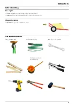
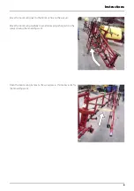
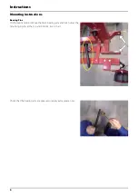
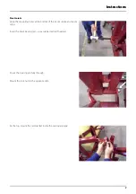
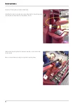
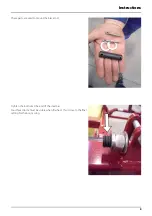
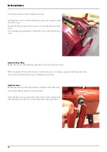
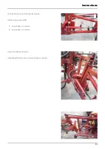
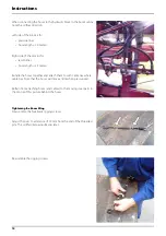
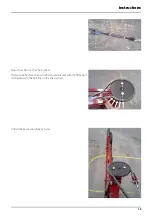
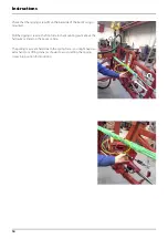
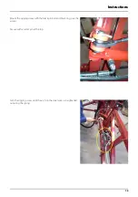
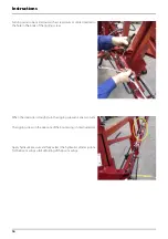
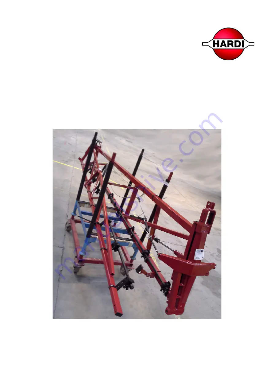
background image

RANGER EAGLE
Boom Wings

Original

Mounting Instruction

67217600-100, version 1.00
GB - 03.2018

www.hardi-international.com

Summary of Contents for RANGER EAGLE

Page 1: ...RANGER EAGLE Boom Wings Original Mounting Instruction 67217600 100 version 1 00 GB 03 2018 www hardi international com...

Page 2: ...roduct Mounting Instruction Formalities The original mounting instruction is approved and published in English All other languages are translations of the original mounting instruction In the event of...

Page 3: ...n your HARDI sprayer They represent the boom wings to be connected to the boom centre Where on the Sprayer On the left and right sides of the boom centre Tools and Materials Needed Crane or forklift t...

Page 4: ...actor during the mounting work Release the oil pressure to start with Keep children and bystanders at a distance Lifting The Boom Wing Into Position The following instructions and pictures show the ri...

Page 5: ...m wing near to the boom centre on the sprayer Move the boom wing carefully to avoid damaging other parts on the sprayer during the mounting work Open the boom wing by means of a wood piece this makes...

Page 6: ...ting Instructions Bearing Pins On the boom centre remove the black bearing pins and lock nuts at the mounting points at the top and bottom 4 sets in all Check that the bearing pins are greased or appl...

Page 7: ...oles at the bottom of the boom centre and boom wing Insert the black bearing pin use a rubber mallet if needed Knock the bearing pin fully through Mount the lock nut on the opposite side At the top mo...

Page 8: ...ole Note that the boom wing has been raised beyond this mounting point allowing the red bracket to be mounted as shown Prepare the mounting hole for the black steel bar connected to the boom centre Ra...

Page 9: ...ructions 9 These parts are used to mount the black rod Tighten the locknut at the end of the steel bar Four thread turns must be visible when finished this is close to the final setting for the boom w...

Page 10: ...Wing Repeat the steps for mounting the opposite boom wing in the pivot joints When completed lift the boom wing to a horizontal position and place a support under the boom wing Now return to the first...

Page 11: ...ctions 11 Connect the hoses to the hydraulic cylinder Tightening torque 28 Nm 1 Hose length 2 0 meters 2 Hose length 2 3 meters Hoses for other boom wing Note the path from boom centre to hydraulic cy...

Page 12: ...le the hoses together and attach them to with cable ties where cable ties Note that the hoses will move a little when pressurized Refrain from attaching hoses and cables to the moving steel parts in t...

Page 13: ...ons 13 Adjust the chain on the chain wheel There is to be five free chain rolls after the red bracket with the fifth chain roll aligned with the bolt line on the chain wheel Unfold the boom wing fully...

Page 14: ...nted Pull the rigging screw on the front side to the mounting point above the hydraulic cylinder on the boom centre The pulling may seem hard due to the spring force you might need an extra hand or a...

Page 15: ...s 15 Mount the rigging screw with the black pin bolt and black ring see the arrow Secure with a cotter pin at the top Turn the rigging screw until the arch on the steel wire is straightened out along...

Page 16: ...the body of the rigging screw When the steel wire is straight turn the rigging screw an extra two turns The rigging screw on the opposite of the boom wing is not adjusted yet Apply hydraulic pressure...

Page 17: ...centre no dismounting until they can be turned by hand Wrench size 24 mm This will facilitate the boom movements when driving in the field Position of the four bolts in the vertical boom structures P...

Page 18: ...horizontal position The bubble in the spirit level should just be touching black line as shown here then the adjustment is all right To adjust the boom wing up or down turn the nuts holding the black...

Page 19: ...driving in the field both boom wing tips are adjusted to be a little ahead at standstill B The adjustment is to be 1 cm forward per boom meter Check again that the boom wings are fully unfolded be mea...

Page 20: ...ine Measure horizontally from a fixed point on the first nozzle holder and out in front of the boom to another fixed point In this case a laser light is positioned on the boom centre and marking the c...

Page 21: ...st the boom wing if needed by changing the position for the ram eye on the fully extracted hydraulic cylinder This is done by turning the nut and the black piece to either extract or retract the pisto...

Page 22: ...htening the Boom Wing Turn the rigging screw to tighten the steel wire in the same way as before This will allow the boom wing to fit into the transport bracket above the wheels on the sprayer Steel w...

Page 23: ...c cylinder parts as shown to move the boom wing into position Modification of Nozzle Bracket In the transport bracket this nozzle bracket will collide with the black support blocks thiswill leadto dam...

Page 24: ...Instructions 24 Drill two holes for pop rivets through the bracket and the red steel pipe Disassemble the nozzle bracket Cut off the a piece of the bracket as shown...

Page 25: ...uctions 25 Mount the nozzle bracket using two pop rivets Check that the boom wing rests on the black support blocks without contact with the nozzle bracket Repeat for the other boom wing Mounting comp...

Page 26: ...Instructions 26...

Page 27: ...menu on the left 3 Select Spare parts catalogue and find your spare part 4 Online ordering is also possible 5 Contact your HARDI dealer for further information on spare parts User Evaluation Dear Rea...

Page 28: ...HARDI INTERNATIONAL A S Herthadalvej 10 DK 4840 N rre Alslev DENMARK...

Reviews: