background image

Summary of Contents for 162272

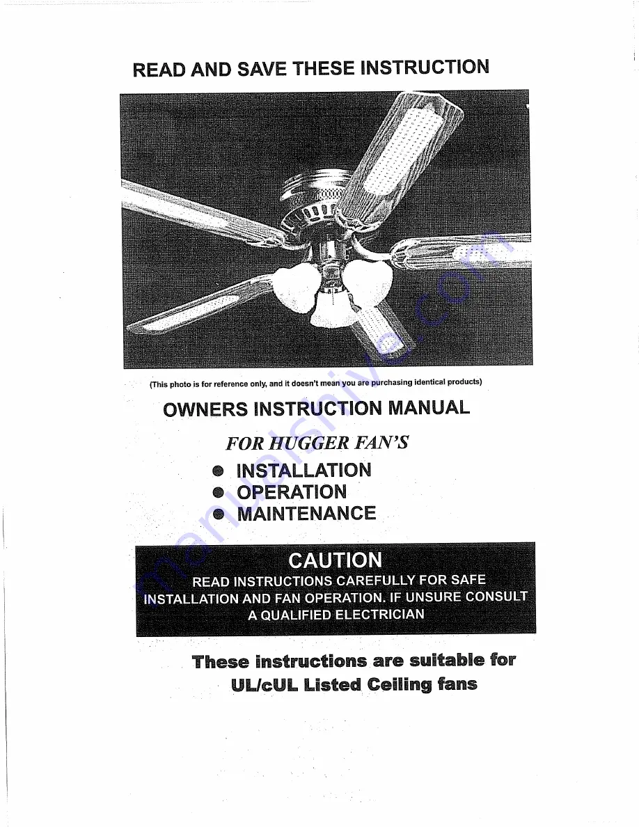
Page 1: ...K This photo is for reference only and it doesn t mean you are purchasing identical products OWNERS INSTRUCTION MANUAL FOR HUGGER FAN S m INSTALLATION OPERATION MAINTENANCE These instructions are suitable for ULfeUL Listed Ceiling fans ...

Page 2: ...g Your Fan 3 Tool and Material Required Electrical Outlet b o x 4 Install Mounting Bracket and Fan 5 Electrical connections 7 Blade Attachment 8 Installing Light kit 9 12 Operation 13 Maintenance 14 Trouble Shooting 15 16 Part List 17 Page 1 ...

Page 3: ...s should be turned upward and pushed carefully up into outlet box The wires should be turned spread apart with the grounded conductor and the equipment grounding conductor on one side of the outlet box 10 WARNING To reduce the risk of fire electrical shock Do not use this fan with any solid state fan speed control device or rheostat 11 Do not insert anything into the fan blades while they are rota...

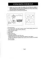
Page 4: ... parts You should have the following 1 Mounting Bracket 2 Fan Housing Motor and switch housing Remove rubber shipping spacers from motor Keep them in case you need to return fan 3 Motor decorative housing 4 Set of Blades 5 Blade Arms 6 Light Kit Optional 7 Parts pack Containing AI Mounting bracket hard wares wire nuts B Blade attachment hard wares screws with washers for each blade CI Blade arm at...

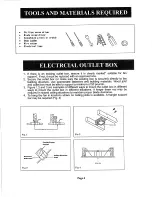
Page 5: ...g structure Use appropriate fasteners and building materials Wood joist arid outlet box must be able to support a minimum of 50 pounds 3 Figure 1 2 and 3 are examples of different ways to mount the outlet box in different ways to mount the outlet box in different situations A longer down rod may be required in sloped ceiling situations to maintain proper blade clearance 4 To hang the fan in locati...

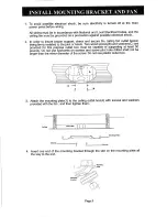
Page 6: ...ed to the joist or beam Two wood screws B and washers C are provided for this purpose outlet box must be capable of supporting at least 50 pounds Do not use lubricants on screws and screw pilot hole drilled shall not be larger than the minor diameter ofthe screw Do not use plastic outlet box V n V 4_ I 3 Attach the mounting plate 1 to the ceiling outlet box A with screws and washers provided with ...

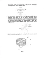
Page 7: ... conductor of the power source Connect the wires by wire nuts provided After splices have been made Carefully push the green and white wires into the outlet box on one side and the black and blue wires on the other side Make wire connections refer to section titled Electrical connections For cUL listed fan please secure the safety cable to the junction box Mounting Plate Mounting ttwclwl Mtrtr Hvt...

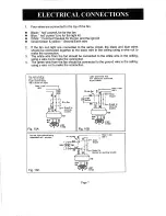
Page 8: ...wire nut to make the connection 3 The white wire from the fan should be connected to the white wire in the ceiling using a wire nut to make the connection 4 The green wire from the fan should be connected to the ground wire in the ceiling using a wire nut to make the connection FEB controlled by pulI chain switch Ujht control led by chain switch on fight Fig 10A Light controlled frm nail EHitch Fa...

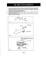
Page 9: ... As most fan use concealed screw blades arms screws may not go through the whole blade arms 2 Tighten each screw starting with center screw 3 Fasten blade assembly to motor with provided screws Repeat procedure for remaining blades Fig 11B 4 Make sure the blades are more than at least 7 feet from the floor avoid any object in the path of the blades SCREWS 4fr r zz3 BLADE zz3 BLADE ARM Fig 11 Page ...

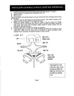
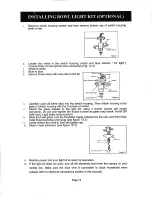
Page 10: ...t kit using 3 thumb screws per shade provided Do not over tighten the thumb screws as glass may break Install 60 watt max light bulbs not provided Glass shade thumb screws are not provided on the spot light fan Restore power and your light kit is ready for operation If the light kit does not work turn off the electricity and lower the canopy on your ceiling fan Make sure the blue wire is connected...

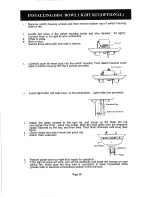
Page 11: ...ulbs 60 watt max to the lampholder Light bulbs not provided i Threaded Tube _l ull Chniii Exteiiiian Attach the glass shades to the light kit and screw up the finial Do not over tighten the finial glass may break Slide the bowl glass over the threaded nipple followed by the cap and then finial Twist finial clockwise until snug see figure Lower chains thru hole in bowl and glass cap ft j Attach cha...

Page 12: ...using the wire nuts provided Align the three holes on the light pan with the three holes on the switch housing rim Secure the light pan onto the switch housing with the three screws and washers provided Install the light bulb not included onto the lampholder sockets Uses maximum 40 watts as the warning label suggested The glass shade belongs to the twist and lock type The rim of the glass shade co...

Page 13: ...glass shades to the light kit using 3 thumb screws per shade provided Do not over tighten the thumb screws as glass may break Install 60 watt max Light bulbs not provided 8 Slide the bowl glass over the threaded nipple followed by the cap and then finial Twist finial clockwise until snug see figure 12 2 9 Lower chains thru hole in bowl and glass cap 10 Attach chain extension see figure 12 3 11 Res...

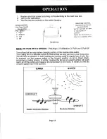
Page 14: ... Low 4 Pull Off Turn off and let fan stop before changing setting of the reverse slide switch Your ceiling fan is a sensible choice to cool as well as help you warm your living area You will have a reduction in both heating and cooling costs by regular use of your fan In summer put the reverse switch in the forward position so air is blown down producing a cooling breeze In winter reverse the fan ...

Page 15: ...attaching the glass screws are tightened 2 Clean your fan periodically Use only a cloth dampened with a mild detergent solution Never use solvents Dust with a soft cloth or brush Metal finishes are finished with a lacquer to prevent tarnishing 3 You will never need to oil your fan Its permanently sealed bearing will prevent silent trouble free operation for many years 4 Make sure the power is turn...

Page 16: ...ing against each other or against wall of housing Wrap with electrical tape if necessary 6 Use of standard light rheostat or unapproved wall control will always cause harmonic distortions or a humming noise Many fan motors do not work quietly with solid state variable controls If a quiet wall control is desired use only approved wall controls 7 Make sure the canopy is not touching the ceiling 8 As...

Page 17: ...ining blades until the wobble is removed 6 You can also look up at the fan from below make sure that none of the blade holders are bent so that a blade is out of position Correction may be made by GENTLY bending the blade holder back into position 7 Blade tracking may be checked simply by use of a household yardstick as shown in below Figure Place the yardstick vertically against the ceiling and e...

Page 18: ...ing 1 Pull Chain tassel 3 speed 1 Screws 4 Decorative housing 1 Screws 12 15 18 Blades 4 5 6 Screws 8 10 12 Screws 3 Thumb screws 9 12 Light Kit 3 4 5 Pull Chain tassel Light switch 1 Glass 3 4 5 Spot Light 3 4 Light Fitter 1 Thumb Screw 3 Glass 1 Safety cable for cUL listed fan only 1 Made in China Page 17 ...

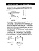
Page 19: ...ed screw Fig 2 I B j Attach the mounting bar to the mounting plate with the locked washers and locked screws using a screwdriver Tighten the three locked screws securely Place the decorative housing over the motor assembly and against the ceiling to match with the holes in the perimeter of mounting plate Secure the housing to the mounting plate with the screws removed in Fig 2 Tighten these four s...

Reviews: