background image

HARGASSNER Ges mbH

A 4952 Weng OÖ

Tel.:  +43/7723/5274-0

Fax.: +43/7723/5274-5

office@hargassner.at

www.hargassner.at

O p e r a t i o n   m a n u a l

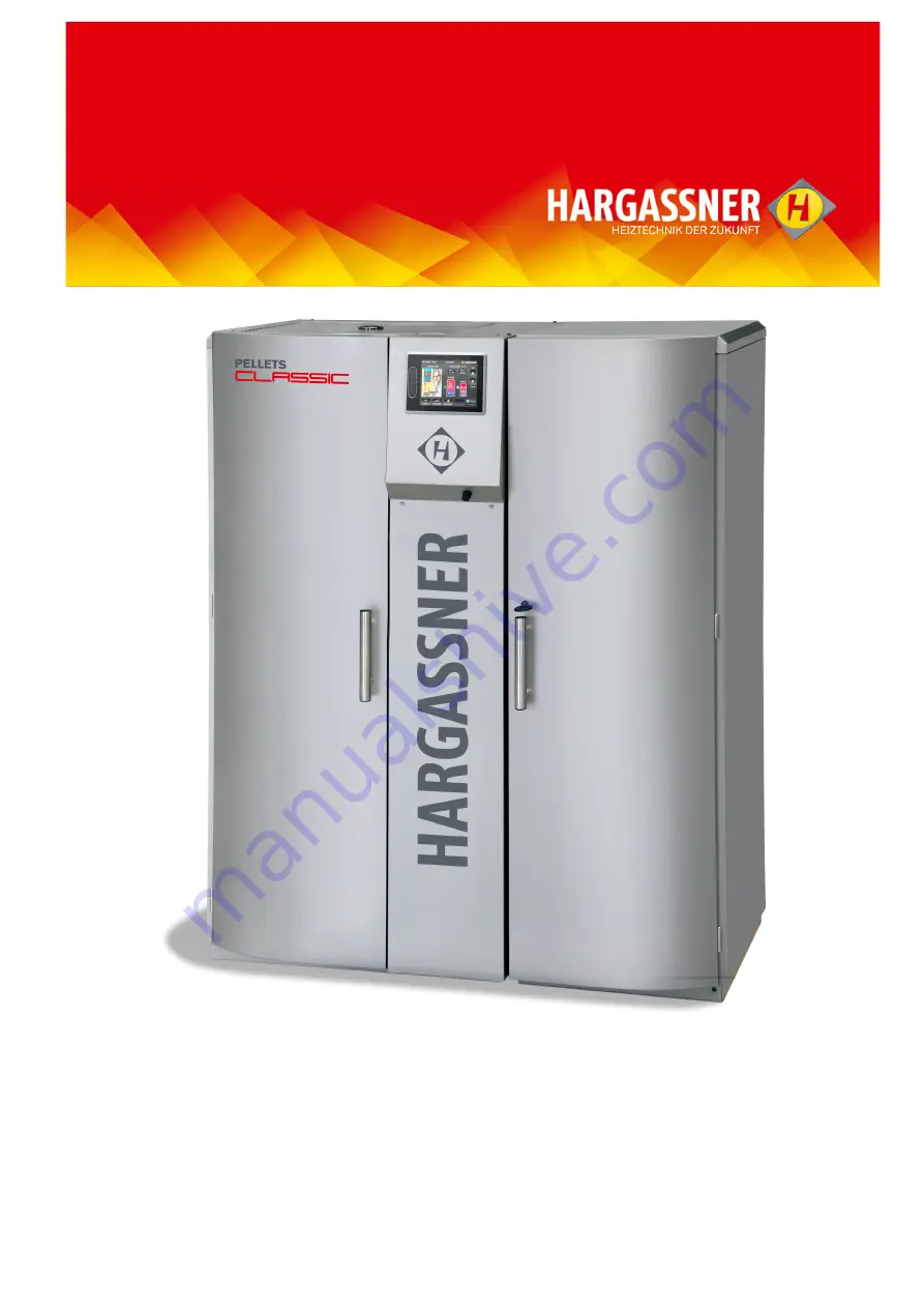
P e l l e t   B o i l e r

C l a s s i c   1 2 - 2 2

EN

 - V01 04/2019 - 11059730

Follow and store this manual


Summary of Contents for Classic 12

Page 1: ...A 4952 Weng OÖ Tel 43 7723 5274 0 Fax 43 7723 5274 5 office hargassner at www hargassner at O p e r a t i o n m a n u a l P e l l e t B o i l e r C l a s s i c 1 2 2 2 EN V01 04 2019 11059730 Follow and store this manual ...

Page 2: ...isks 8 3 Measures in case of danger 10 Chapter III Operation 11 1 Overview of components 11 2 Prior to commissioning 12 3 Control panel 14 4 Operating modes 17 5 Boiler s status indicators 18 6 Info menu 21 7 Manual operation 25 8 Settings menu 28 9 Customer settings 31 10 Installer settings 37 11 Optional remote controls 49 Chapter IV Cleaning Maintenance 51 1 Maintenance contract 52 2 Cleaning a...

Page 3: ...l lation commissioning and service is just as crucial Supportive are attached hydraulic schematics and connections and installation drawings To ensure a long service life exactly read and follow this operation manual High costs for reparation and long downtimes may be prevented Keep this manual within easy reach The operating manual is intended to help become familiar with the boiler and to use it...

Page 4: ...el quality Only use fuels that comply with EN ISO 17225 2 replaces ÖNORM EN 14961 2 3 1 Wood Pellets A1 Ensure these quality standards are adhered to when wood pellets are ordered and delivered Least possible dust content Wood pellets with a hard and shiny surface 100 natural wood no additives etc Wood pellet class A1 defined in EN ISO 17225 2 2014 and ÖNORM M 7136 B H T Designation Description Va...

Page 5: ...of the fuel storage room in the installation manual Only install metal fill pipes electrically grounded and connection to atmosphere Pay attention to noise protection Protection against moisture water and dust Correctly position impact protection mat s and install slant floor 6 Execution of heating circuits The heating circuits must be designed correctly for optimum operation of the boiler Authori...

Page 6: ...s absolutely imperative that the intrinsically safe cables are permanently installed Use suitable mechanical components in phase connection L and N see electrical manual Connect potential equalisation Use highly flexible cables e g H05VV F Description Unit Classic 12 Classic 14 Classic 15 Classic 22 Nominal heating output KW 12 0 14 9 15 0 22 0 Flue gas temperature C 150 150 150 150 CO2 14 Mass vo...

Page 7: ...r commissioning on page 12 Do execute verifications prior commissioning See Inspections prior starting up the boiler on page 13 D A N G E R Risk of death injuries damage from inappropriate installation Observe the safety instructions of the boiler and in the operation manual Read the user manual PRIOR to commissioning In the cladding door is a storage compartment Incorrect actions by unauthorized ...

Page 8: ...mediately Before performing any maintenance work on the water circulation system depres surise the boiler Check if all valves are in correct position D A N G E R Dust explosion due to electro static charging in the fuel storage room Pay attention to proper grounding of the pellets transportation tubes No motors in the fuel storage room acc to country specific regulations Except agricultural buildi...

Page 9: ...serve fuel storage room sticker D A N G E R Electric shock from contact with live terminals Observe information signs Before starting work check that no voltage is present using a voltmeter D A N G E R Poisoning and danger of suffocation due to flue gases in the boiler room building Check boiler doors and seals for leaks Burning treated wood paint varnish impregnation results in toxic ash Avoid sk...

Page 10: ...ure increases the boiler will heat up and control the transfer of heat according to the preset parameters 3 3 Leak in heating water system no water If the water pressure is too low not enough heat is being transferred from the boiler to the heat circuits HWT and accumulator Danger of boiler overheating Turn off the boiler Fix leakiness fill refill water system Check water pressure 3 4 Leak in the ...

Page 11: ...ts takes place through the automatic Ignition 1 1 Function Fuel transport from the storage room Transport of the fuel into the combustion chamber Ignition and combustion of the fuel Control of energy transfer to the water based system Cleaning of the boiler and the ash extraction into the box Evacuation of the flue gases Pos Description 1 Fully refractory lined combustion chamber 2 Sliding grate 3...

Page 12: ...function Safety devices should not be modified or bypassed In case of a malfunction or defect perform repair measures immediately Place position and function of all safety devices must be known W A R N I N G Danger of crushing from moving parts in the vicinity of the fuel extraction system ash extraction system and combustion grate Make sure that no persons stay in any danger zone Do not reach int...

Page 13: ...or due to missing fuel Switch the boiler to Auto or HWT mode Boiler starts automatically when hot water is needed 2 5 Air flow slider settings The air flow slider above the ash box is set at the factory Classic 12 15 one hole line open Classic 22 all holes lines open 2 6 Inspections prior starting up the boiler Check the water pressure in the boiler heat HWT and accumulator circuits Pay attention ...

Page 14: ...ly trained staff should operate the control unit Access to all functions of the control is protected by codes in the control unit Service settings and installer settings Codes may not be forwarded to unauthorised staff 2 1 3 4 Off Summer Winter Home Pos Description Function 1 Standard menu Changes from Home to standard menu See Standard menu view on page 16 2 Operating mode Off Quick select button...

Page 15: ...o the standard menu press Standard you may have to press twice Possible from every menu Activate the operating mode by pressing the Function selection button Press the field to activate the input field Values are displayed in red Change the active values Values flash red Buttons flash green To enter or save any changes press You can go straight to the customer parameters by pressing the relevant g...

Page 16: ... the current water temperature in the HWT 7 Status display of heating circuits Heat circuits switched off Sun Heat circuits in day mode Moon Heat circuits in reduced mode Frost Heat circuits in frost protection mode 8 Display of outside temperature Outside temperature measured at outside sensor 9 Settings Takes you to the customer installer and service settings and to the controller s setup menu 1...

Page 17: ...The following options are available Full load If an accumulator is connected press this button to have the control unit automatically change to full load measurement Empty accumulator Press this button to switch off all programmed con trol functions of the boiler The boiler operates at full load assumes very low outside temperatures and tries to transport as much as possible heat into the heating ...

Page 18: ...g transported into the combustion chamber and the boiler monitors if an autonomous ignition is possible due to residual embers Ignition The electric ignition starts and the fuel is ignited Combustion The boiler controls the induced draft fan s output air volume according to the heat demand and required boiler temperature and the optimum fuel amount according to the lambda sensor signal Combustion ...

Page 19: ...time is exceeded no more fuel is added and the boiler burns out Deashing The grate is opened and closed twice The generated ash drops down into the ash box The boiler returns to the required status afterwards Pellets fill in If the minimum auger run time and the set suction time are reached or the maximum auger run time is exceeded the filling will be started after the displayed time BOILER Slumbe...

Page 20: ...52 Weng OÖ Tel 43 7723 5274 0 Fax 43 7723 5274 5 office hargassner at III Refill pellets The vacuum turbine is started up and the day hopper is filled with wood pellets again The boiler subsequently returns to the required status BOILER Refill pellets ...

Page 21: ... circuits One heat circuit is displayed per page If there are several heat circuits several info pages are available in the menu If the mixer pump is running this is indicated as text and by a green arrow icon Use the symbol next to the heat circuit 1 to call up the configuration pages You can also press the heat circuit button directly to go to the first heat circuit page If a FR25 FR35 or FR40 i...

Page 22: ...t circuit is used to jump to the setting options in the configuration pages 2 Heating mode configuration The button is used to enter the pop up menu for selecting the heating mode 3 Heat circuit Off The heat circuit is switched off except for the frost protection function 4 Heat circuit Automatic The heat circuit runs according to the timer programme s settings 5 Heat circuit continuous setback Th...

Page 23: ... values of the external heat External heat operation indicator On Off Current external heat sensor temperature External heat valve indicator On Off 6 9 Consumption info Info page about the current overall consumption Only displayed if the pellet consumption display is activated in the installer settings 6 10 Info Trend Diagram of the last 24 hours Boiler temperature HWT temperature Power Accumulat...

Page 24: ...les suction turbine 9h 9h 0 0h 9h 7 34h 5 8h 0 0 0 HARGASSNER Mo 25 11 18 08 19 Runtime LB since ashing Total run time combustion Total run time superelevation ST runtime since pellet filling Pellet filling no earlier than Pellet filling no later than Dis De ash cycles Cleaning for number of de ash cycles Number of SR movements 180 Min 60 Min 180 Min 0 Min 30 Min 300 Min 0 1 0 HARGASSNER Mo 25 11 ...

Page 25: ...e grate will close No 4 Function and rotation check of ash extraction motor Manual Forward or Backward of the motor Press Backward button only briefly No 5 Function and rotation check of stoker auger motor Manual Forward and Backward to fill the stoker auger Press Backward button only briefly The stoker auger is only available without sliding grate when the service set tings are activated No 6 Fun...

Page 26: ...unction check or manual operation of heat circuit pumps No 19 for heat circuit pump A HC A Nos 21 and 23 for heat circuit pumps 1 and 2 Boiler Nos 25 27 and 29 for heat circuit pumps 3 and 4 and external heat circuit pump 2 HKM 1 Nos 30 32 and 34 for heat circuit pumps 5 and 6 and external heat circuit pump 3 HKM 2 Function and rotation check of heat circuit mixer No 20 for heat circuit mixer A HC...

Page 27: ... Acc to parametrised heating system HARGASSNER Mo 25 11 18 08 19 On No 36 Manual Boiler circulation or accumulator pump HARGASSNER Mo 25 11 18 08 19 On No 37 Manual Heating circuit valve HARGASSNER Mo 25 11 18 08 19 On No 38 Manual Fault lamp ext pump district line pump HARGASSNER Mo 25 11 18 08 19 On No 41 Manual controlled district line pump HARGASSNER Mo 25 11 18 08 19 On No 42 Manual Controlle...

Page 28: ...ote Installer and Service menu are protected by a PIN code Only service personnel may change them as the parameters may impair the functionality of the heating system if poorly selected 8 4 Setup The following setting options are available Display settings Network settings Parameter download SD Data recording SD 8 4 1 Display settings No 01 Display standby Activates or deactivates the standby mode...

Page 29: ...of the Secondary DNS Server No 010 Display of the Name of Device L No 011 IP address of the KNX module HARGASSNER Do 22 11 18 08 41 No 02 Display settings Home screen after Default 2 min 2 Min HARGASSNER Do 22 11 18 08 41 No 03 Display settings Backlight Default 100 100 HARGASSNER Do 22 11 18 08 41 No 03a Display lock code No Yes HARGASSNER 1 2 3 4 5 6 7 8 9 C 0 0000 Do 22 11 18 08 41 No 03b Displ...

Page 30: ...3 5274 0 Fax 43 7723 5274 5 office hargassner at III 8 4 3 Parameter download SD Save the set parameters to SD Card inserted Press Save parameters 8 4 4 Data recording SD Additional saving of current boiler data on the SD card To finish the protocol press Stop SD Logging ...

Page 31: ...ing the loading times of the boiler using the day clock 9 1 2 Week clock No 1a HWT 1 week clock Setting the loading times of the boiler using the weekly clock Selected day green 9 1 3 Setpoint temperature No 2 HWT 1 Setting the HWT set temperature HWT loading is done only during the set loading times 9 1 4 Circulation pump No 2a HWT 1 circulation pump Setting the switching times of the circulation...

Page 32: ...set value the heat circuits will be switched off summer shut down No 12 All heat circuits off day reduction If the average outside temperature exceeds the set value during the day reduction time the heat circuits will be switched off No 13 All heat circuits off night reduction If the average outside temperature exceeds the set value during the night reduction time the heat circuits will be switche...

Page 33: ...he Yes button to start the deashing and cleaning process 9 4 3 Date Time No 20 Date time Setting the date and time 0 C 8 C 16 C 5 C 10 C 00 00 24 00 12 00 15 00 21 00 18 00 06 00 09 00 03 00 EXTERNAL HEAT EXTERNAL HEAT Off Outside temperature HEATING ACTIVATED HEATING ACTIVATED Day reduction ACTIVATED Night reduction ACTIVATED HARGASSNER Mo 25 11 18 08 19 No 14 Automatically refill and suction tim...

Page 34: ... Deviations of up to 20 possible 9 4 6 Fresh water station No 32 Fresh water station Setting the maximum temperature of the hot water at the tapping point Only active if parameter C3 in the installer settings is on Accumulator Fresh water station HARGASSNER Mo 25 11 18 08 19 No 22 Heater OFF 20 M 11 2018 0 00 00 HARGASSNER Mo 25 11 18 08 19 No 30 Pellet storage 0 kg 1000 kg Storage volume guidelin...

Page 35: ...eat circuit 2 Reduction temperature 16 0 C 2135 Menu Description Factory Modbus ad dress HP1 HWT A daily Mon Sun ON 17 00 OFF 20 00 2140 HP 1a g HWT A weekly Mo Tu We Th Fr Sa Su ON 17 00 OFF 20 00 2145 2175 HP 2 HWT A Set temperature 60 C 2180 HP 2a Circulation pump HWT A ON 06 00 11 00 OFF 08 00 13 00 2185 HP 3 Heating circuit A daily Mon Sun ON 06 00 15 00 OFF 09 00 22 00 2190 HP 3a g Heating c...

Page 36: ...Sa Su ON 06 00 15 00 OFF 22 00 09 00 2475 2505 H 17 Heat circuit 6 Day room temperature 20 0 C 2510 H 18 Heat circuit 6 Reduction temperature 16 0 C 2512 Menu Description Factory Modbus ad dress Menu Description Factory Modbus ad dress No 11 Heating off at outside temperature over 16 2514 No 11a h Heat circuit 1 A and ext HC off at outside temperature 16 2515 2522 No 12 All heat circuits off at da...

Page 37: ...ith the green checkmark 10 1 Parametrising the heat circuits and HWT Standard parameters on the boiler control board Heat circuit 1 No A1 No A9 Heat circuit 2 No A11 No A19 HWT 1 No B1 No B8 Extension module 1 HKM1 Heat circuit 3 No A21 No A29 Heat circuit 4 No A31 No A39 HWT 2 No B11 No B18 Extension module 2 HKM2 Heat circuit 5 No A41 No A49 Heat circuit 6 No A51 No A59 HWT 3 No B21 No B28 Heat ...

Page 38: ...ess Name to name each heat circuit separately e g Living room No A2 Steepness Describes the relationship between flow and outside temperatures see heating curve Range 0 2 3 5 Recommended settings Floor heating 0 3 1 0 Radiator heating 1 2 2 0 Convector heating 1 5 2 0 Change in small steps only and for a longer period HARGASSNER Mo 25 11 18 08 19 non existent Pump Mixer Loxone Mixer Floor Heating ...

Page 39: ...set temperature is exceeded by the set value No M6 service parameter the heat circuit pump switches Off and the mixer is Closed Pump and mixer switch On again when the room temperature drops below the set room temperature by the preset value service parameter M6a No A7 Activate district line pump when heat circuit pump 1 is running No A8 Activation of summer heating function of the corresponding h...

Page 40: ...he HWT time pro gramme customer setting no 1 Range 1 80 C No B4 Activate the Legionella protection programme No B5 HWT set temperature for legionella protection Temperatures of 70 C or above for more than 3 minutes will kill all legionella in the HWT No B6 Leg prot week prog Green active Start legionella protection during HWT loading only HARGASSNER Mo 25 11 18 08 19 AT minimum temperature Default...

Page 41: ... module 1 B21 B29 When using an extension module 2 B31 B39 When using a heat circuit board A Setting options See installer settings B1 B9 No B60 HWT priority operation for quick HWT loading For heat circuits with pumps the heat circuit pumps are switched off through out HTW priority operation No heat is transferred from the boiler to the heat circuits For heat circuits with mixers and pumps the he...

Page 42: ...n No C3a Accumulator sensor selection Acc in the boiler room Select AT sensor boiler Acc next door HKM Select Accumulator sensor HKM 1 2 No C4 End AT loading measured on accumulator sensor below Only displayed when installer setting C2 is set with 2 3 or 5 sensors If heat is requested the accumulator is loaded to its set temperature C4 60 C bottom accumulator sensor No C4a Accumulator Presetting t...

Page 43: ...nal 83 on the main board Fault lamp Lights up for all faults Pump external heat circuit Boiler is heated to the temperature set in parameter C6 External heat circuit pump is switched on at release temperature service setting L5 District line pump District line runs when a heating circuit or HWT pump parametrised for district line is switched on No C8 External heat circuit and district heat pump Di...

Page 44: ...s are switched on when the value drops below the set value Heat circuits with mixers are adjusted to the D3 parameter temperature No D3 frost protection Flow temperature when parameter D2 is not reached No D4 Lambda sensor Specify whether or not the boiler is equipped with a lambda sensor If the lambda sensor is defective this setting can be changed to Not availa ble No D5 Changeover day setback r...

Page 45: ...resentation of records in the Info History menu field should be shown No D24 Modbus activated Specify whether a Modbus is available Only visible when a Modbus ID card is inserted No D25 KNX activated Specify whether a KNX building controller is available Only visible when a KNX ID card is inserted No D32 Contr district line If there is a demand from a heat circuit parametrised on a controlled dist...

Page 46: ...ting message output If lambda heating is active an operating message signal is issued at the set terminal No D50 Manual pellet de ash customer Set whether de ashing is carried out manually No D65 Error output 10 6 Parameter E languages No E1 Language Language selection HARGASSNER Mo 25 11 18 08 19 Mixer runtime Default 140 seconds No D33 Contr district line 140 Sec HARGASSNER Mo 25 11 18 08 19 Fue...

Page 47: ...ircuit 2 is activated when the sensor temperature S1 is higher than the temperature at the parametrised sensor installer setting G5 by the preset value Range 1 50 C No G5b Differential controller Switch difference Indicate what the differential temperature between the two sensors being used has to be If it has dropped below circuit 2 is activated Range 1 50 C No G5c Differential controller Shut do...

Page 48: ...hich temperature difference between the two sensors being used must be switched Range 1 50 C No G7 Differential controller Safety circuit If the preset temperature is reached at the parametrised sensor all the out puts on the differential controller board will be switched off Range 80 105 C If 95 C is exceeded at a sensor excluding S1 then differential control will be deactivated to prevent damage...

Page 49: ... FR40 With the FR40 all the heat circuit functions available on the boiler can be set from wherever the remote control is in the user s living space Operation modes Off The heat circuit is switched off except for frost protection AUTOMATIC The heat circuit is operated according to set times REDUCTION in automatic mode The heat circuit is in permanent reduced mode HEATING in automatic mode The heat...

Page 50: ...ction on a single occasion The heat circuit switches to permanent reduced mode on a single occasion and automatically reverts to automatic mode at the next preset heating time Fine adjustment of room temperature Increase decrease by 2 or 3 C Fault lamp Lights up if an error occurs on the boiler Display Parameters Select which temperature should be shown on the remote control FR35 HWT temperature 1...

Page 51: ...ing or maintenance works Switch off and lock main switch D A N G E R Risk of injury from reaching into the danger zone when recommissioning After triggering the main power switch do not carelessly reach into the danger zone Before carrying out any work on the boiler and its equipment turn off the main pow er switch and prevent it from being turned on again by securing it with a padlock Keep the ke...

Page 52: ...d by personnel authorised by Hargassner Depending on your country s regulations a service must be carried out by the manufacturer regularly every one to three years This service has to be carried out by personnel trained and authorised by the manufacturer In order to perform at its best the boiler must be cleaned extensively At least once a year After a set number of operating hours in the event o...

Page 53: ...s 8000 partial load hrs or after a message has appeared on the control panel 1 Tap off the turbulators and clean the turbulator space 1x a 2 Clean flue pipe 2x a 3 Clean post combustion chamber with poker visual check via inspection glass 1x a as required 4 Clean combustion chamber with poker 1 x a as required 5 Remove ash box and clean out the ash under the grate 1x a 6 Dismount exhaust fan and c...

Page 54: ...the lid up to remove it 2 2 Cleaning the lambda sensor Disconnect sensor and unscrew Place sensor head down and remove dirt with a soft cloth Debris falls down 2 3 Cleaning the exhaust fan and the flue pipe Remove baffle Clean flue pipe Clean housing and impeller of the exhaust fan Fasten impeller while cleaning Do not clean with compressed air 2 4 Cleaning the turbulators and the turbulator space...

Page 55: ... which the flame enters the post combustion chamber If the flame concentration hole is jammed or the post combustion chamber 10 is very dirty disassemble the front maintenance door M6 cap nuts and clean the post combustion chamber with the cleaning poker Remove ash box and clean combustion chamber 11 with cleaning poker Cleaning the ash box 12 N O T E Clean combustion chamber when exhaust fan is r...

Page 56: ...Push the clamps 1 apart on the housing Press the clamps 2 on the carbon brushes apart with a screwdriver and remove the housing cover 3 Remove the screws 4 and the retaining plate 5 Remove the flat receptacle 6 Replace the carbon brushes two pieces with new ones Re assemble the unit in reverse order 2 8 Emptying the ash box Empty the ash box at the regular intervals The control shows Empty ash box...

Page 57: ...rtilizer Attention Watch out for ember pockets 3 2 Disposal of wear and spare parts Wear and spare parts must be disposed of according to your national waste management regulations Austria AWG Waste Management Act Only use spare parts from Hargassner or spare parts approved by Har gassner 3 3 Disposal of boiler components Ensure environmentally compatible disposal in accordance with country spe ci...

Page 58: ...press Error 2 Display of error list latest errors 3 Acknowledging and rectifying an error After rectifying the error press the button 3 1 List of error messages and parameter lists See Service manual A T T E N T I O N Injuries or damage to the boiler due to deviations from regular operation Contact the installer Hargassner immediately in case of higher power consump tion higher temperatures more v...

Page 59: ...delines in this operation manual please follow general guidelines for safety and accident prevention The manufacturer Hargassner Ges mbH shall not be liable for direct or consequential damage resulting from failure to observe the technical instructions guide lines and recommendations The vast experience of Hargassner Ges mbH latest production technology and highest quality standards guar antee the...

Page 60: ...Machinery Directive 2006 42 EC Low Voltage Directive 2014 35 EU EMC Directive 2014 30 EU Conformity with the guidelines is verified through the manufacturer s compliance with the relevant requirements which are laid down in the following standards among other places Standards EN 303 5 2012 Heating boilers for solid fuels manually and automatically stoked nominal heat output of up to 500 kW EN ISO ...

Page 61: ...VI HARGASSNER Heating technology for Biomass A 4952 Weng OÖ Tel 43 7723 5274 0 Fax 43 7723 5274 5 office hargassner at 61 notes ...

Page 62: ...62 HARGASSNER Heating technology for Biomass A 4952 Weng OÖ Tel 43 7723 5274 0 Fax 43 7723 5274 5 office hargassner at VI notes ...

Page 63: ...VI HARGASSNER Heating technology for Biomass A 4952 Weng OÖ Tel 43 7723 5274 0 Fax 43 7723 5274 5 office hargassner at 63 notes ...

Page 64: ......

Reviews: