
Overview
7. RS232 Pass-through:
9. Power on all attached devices:
2. Repeat steps 1 for the CTP-1301 TX/RX.
2. Repeat step 1 for the other side of the CTP-1301 TX/RX
The JPK-1300 Jetpack 3x1 Switching, Transport, and Control solution
includes a 3-input wall-plate transmitter, a multi-function receiver,
and a keypad for control. The purpose of this document is to illustrate
how the solution is to be installed and set up in its simplest configuration
by a trained technician.
The following items are included with the JPK-1300:
• [1] JPK-1300 Wall-plate Transmitter (with Screws)
• [1] JPK-1300 Keypad (with Screws)
• [1] JPK-1300 Receiver
• [1] DC 24V 3.75A Power Adapter
• [2] Power Cords (US&AU for UA version; EU&UK for EK version)
• [1] Phoenix Connector (3.81mm, 2 Pins)
• [4] Phoenix Connector (3.81mm, 3 Pins)
• [1] Phoenix Connector (5.08mm, 4 Pins)
• [1] IR Wideband Emitter Cable (1.5 meters)
• [2] Mounting Bracket (with Screws)
Active power requirements:
• Voltage, DC (typical): 24V DC 3.75A
• Power consumption (max): 80W (TX + RX + Keypad)
The environmental requirements for the JPK-1300 are as follows:
•
Operating Temperature:
32° F (0° C) to 104° F (40° C)
•
Storage Temperature:
-4° F (-20° C) to 140° F (60° C)
•
Operating Humidity:
20% to 90% RH(non-condensing)
•
Storage Humidity:
20% to 90% RH (non-condensing)
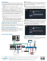
1. Position and install the mounting brackets of JPK-1300 RX with the
4 mounting screws provided, as shown below.
2. Mount and secure the JPK-1300 to a surface or a suitable location
using appropriate mounting screws.
JPK-1300
Jetpack 3x1 Switching, Transport, and Control Solution
AV FOR AN IT WORLD
®
QUICK START GUIDE
JPK-1300 RX
Installation and Connection
What’s in the Box?
Power
Environmental Requirements
Cable Requirements
1. CONTROL port connection distance is up to 164ft/50m via a Shielded
Cat 6/6A/7 cable. The CONTROL cable must be pre-run from the
Wall-plate Transmitter backbox to the Keypad backbox.
2. AV LINK port connection distance is up to 230ft/70m for 1080P video
or 131ft/40m for 4K video via a Shielded Cat 6/6A/7 cable. The AV
LINK cable must be pre-run from the Receiver installation location to
the Wall-plate Transmitter backbox.
Install Jetpack Receiver
Connect Jetpack Receiver
1. Connect the pre-run AV LINK cable to the AV LINK port on the JPK-
1300 RX.
2. Connect the power adapter provided to the JPK-1300 RX.
3. Connect HDMI OUT
Connect an HDMI display device (such as a projector) to the HDMI
OUT port of the JPK-1300 RX.
4. Connect USB DEVICE
Connect an USB device (such as a Smart Board) to the USB DEVICE
port of the JPK-1300 RX.
5. Connect MICROPHONE or OTHER ROOM AUDIO SOURCE
Connect an audio source (such as a microphone) to the MIC/LINE
IN port of the JPK-1300 RX. (Make sure the MIC/LINE switch is turned
to MIC when connecting a microphone to the MIC/LINE IN port.)
6. Connect AUDIO OUT
Connect the AUDIO OUT port to an amplifier or powered speakers
and/or connect the AMP OUT port to 4/8 Ohm speakers using
appropriate speaker cables.
7. Connections for additional control options:
• LAN control (Web UI/PC tool/Telnet/SSH): Connect JPK-1300 RX
to the same network of the PC or control system via the LAN.
• RS-232/IR/RELAY control: Connect the RS-232 or IR OUT port of the
JPK-1300 RX to the display device such as a projector via an RS-232
cable or the IR emitter cable provided, and connect the RELAY
port (1-2) to the electric lifting projection screen.
• Remote mute control: Connect the REMOTE MUTE port of the
JPK-1300 RX to the contact closure of the fire alarm system.
Note:
Please refer to the Instruction manual for the configuration of
RS-232/IR/RELAY control and the REMOTE MUTE.
Connect Jetpack Devices
1. Connect one end of the pre-run CONTROL cable to the CONTROL
port on the JPK-1300 Wall-plate TX and the other end to the
CONTROL port on the JPK-1300 keypad.
2. Connect the free end of the pre-run AV LINK cable to the AV LINK
port on the JPK-1300 Wall-plate TX.
USB-C
HDMI 1 HDMI 2
LINK
PWR
HDCP
SOURCE
USB-C IN
HDMI IN 1
HDMI IN 2
IR
USB HOST
JPK-1300-UA TX
VOLUME
DISPLAY
ON
DISPLAY
OFF
HDMI 1
HDMI 2
USB-C
ON/OFF
SYSTEM
JPK-1300-UA Keypad
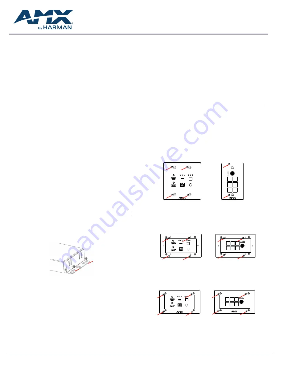
To install the EK version JPK-1300 Wall-plate TX and Keypad:
1. Remove the white screws on the cover of the wall-plate TX and
keypad and remove the cover.
2. Place the wall-plate TX and keypad into an EU standard back box,
and secure with the screws provided, as shown below.
Note:
Use the two screw holes on the left and right ends to install the
EK version wall-plate TX and keypad into UK standard back boxes.
To install the UA version JPK-1300 Wall-plate TX and Keypad:
1. Place the wall-plate TX and keypad into US standard back box.
2. Secure the wall-plate TX and keypad with the white screws provided,
as shown below.
3. Secure the cover back to the wall-plate TX and keypad with the
white screws provided, as shown below.
USB-C IN
HDMI IN 2
PWR
USB-C
HDMI 1 HDMI 2
LINK HDCP
HDMI IN 1
SOURCE
IR
USB HOST
JPK-1300-EK TX
HDMI 2
VOLUME
DISPLAY
OFF
USB-C
HDMI 1
DISPLAY
ON
SYSTEM
ON/OFF
JPK-1300-EK Keypad
Installing Jetpack Wall-plate Transmitter and Keypad
USB-C IN
HDMI IN 2
PWR
USB-C
HDMI 1 HDMI 2
LINK HDCP
HDMI IN 1
SOURCE
IR
USB HOST
JPK-1300-EK TX
HDMI 2
VOLUME
DISPLAY
OFF
USB-C
HDMI 1
DISPLAY
ON
SYSTEM
ON/OFF
JPK-1300-EK Keypad
Connecting Jetpack TX to Source Equipment
1. Connect HDMI / USB-C IN
Connect the HDMI and/or USB-C video sources to the HDMI IN 1, 2,
or USB-C port of the JPK-1300 TX.
2. Connect USB HOST
If using an HDMI input, connect the USB HOST port on the JPK-1300
TX wall-plate to the USB port of the PC.


