EN
JBL Stage A6002/A6004/A9004/A3001
THANK YOU FOR YOUR PURCHASE . . .
Your JBL product has been designed to provide you with the performance and ease of operation you would expect from JBL.
• Please take time to read your owner's manual in its entirety before operating or installing your amplifier.
• Keep the owner's manual for your amplifier in your glove compartment along with the owner's manual for your car.
• Put your amplifier sales receipt with other important documents in order to expedite warranty service if needed.
ABOUT THE MANUAL
This manual describes general installation guidelines and operation instructions. However, please note that proper installation of mobile audio and video
components requires qualified experience with mechanical and electrical procedures. If you do not have the knowledge and tools to successfully perform this
installation, we strongly recommend consulting an authorized JBL dealer about your installation options. Keep all instructions and sales receipts for reference.
Consider this manual as an indispensable feature of your amplifier.
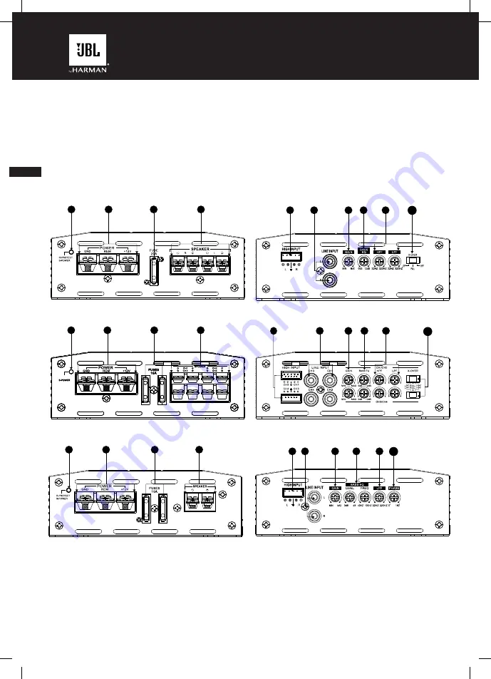
CHAPTER 1: PICTORIAL INDEX OF INPUT
CONNECTIONS
Stage Amplifier left side panel
Stage A6002
Stage A6004 and A9004
Stage A6004 and A9004
Stage A3001
Stage A6002
Stage A3001
1. Power/protect indicator
2. Power input connectors
3. Fuse(s)
4. Speaker output connectors
5. High-level input(s)
6. Line-level inputs (RCA)
7. Gain (input sensitivity)
8. Bass EQ control(s)
9. Crossover frequency control(s)
10. Crossover filter selector(s)
11. Subwoofer phase selector
Stage Amplifier right side panel
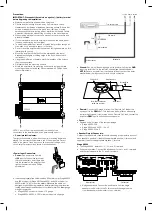
CHAPTER 2: INSTALLATION AND WIRING
What's in the box:
1x amplifier
4x mounting screws x4
Spare fuse (x1 for A6002, x2 for A3001, A6004 and A9004)
High-level input adapter (x1 forA6002 and A3001, x2 for A6004 and A9004)
Mounting hardware
Quick-start guide
1
3
2
4
5
9
7
8
10
6
R-PROTECT
R-PROTECT
R-PROTECT
1
2
3
4
32HZ
320HZ
32HZ
320HZ
32HZ
320HZ
32HZ
320HZ
9
6
7
8
5
10
12
5
7
8
9
11
6
1
2
4
3


