background image

© 2011 Harsco Corporation, All Rights Reserved

MFD 202


MODU-FIRE

®

 FORCED DRAFT  

GAS-FIRED BOILER 
2500 - 3000 


Model #:_______ 

Serial #______________________ 

 
Start-Up Date: _______________________ 


Harsco Industrial, Patterson-Kelley 
100 Burson Street 
East Stroudsburg, PA 18301 
Telephone:  (570) 476-7261 
Facsimile:  (570) 476-7247    
www.harscopk.com 


C.S.A. Design-Certified 
Complies with ANSI Z21.13/CSA 4.9 
Gas-Fired Low Pressure Steam and Hot Water Boilers 


ASME Code, Section IV 
Certified by Harsco Industrial, Patterson-Kelley 


C.S.A. Design-Certified 
Complies with ANSI Z21.13/CSA 4.9 
Gas-Fired Low Pressure Steam and Hot Water Boilers 

MODU-FIRE® FD 2500-3000 
Rev. 1.01 (2/7/12) 

Summary of Contents for 1004905923

Page 1: ...Burson Street East Stroudsburg PA 18301 Telephone 570 476 7261 Facsimile 570 476 7247 www harscopk com C S A Design Certified Complies with ANSI Z21 13 CSA 4 9 Gas Fired Low Pressure Steam and Hot Water Boilers ASME Code Section IV Certified by Harsco Industrial Patterson Kelley C S A Design Certified Complies with ANSI Z21 13 CSA 4 9 Gas Fired Low Pressure Steam and Hot Water Boilers MODU FIRE FD...

Page 2: ...MODU FIRE Forced Draft Gas Fired Boiler 2500 3000 2 ...

Page 3: ...stem 26 3 9 Pre Start Check List 26 3 10 Safety Checks 26 3 11 Boiler Operating Control 28 3 12 Combustion Adjustment 29 4 OPERATION 32 4 1 General 32 4 2 Lighting and Shut Down Procedures 32 5 MAINTENANCE 33 5 1 Maintenance and Inspection Schedule 33 5 2 Cleaning the Burner 35 5 3 Removing the Heat Exchanger 36 5 4 After All Repairs or Maintenance 36 5 5 Sequence of Operation 36 5 6 Troubleshooti...

Page 4: ...essential to read understand and follow the recommendations of this manual before installing operating or servicing this equipment Installation and service must be performed by a qualified and knowledgeable individ ual who has been trained on the Harsco Industrial Patterson Kelley MODU FIRE Forced Draft boiler The same features which permit this boiler to achieve high efficiency performance make i...

Page 5: ...s temperature sensors pumps flow switches balancing valves and check valves will be required for satisfactory operation of any system Harsco Industrial Patterson Kelley cannot be responsible for the design or operation of such systems and a qualified engineer or contractor must be consulted 2 SAFETY 2 1 GENERAL The MODU FIRE Forced Draft gas fired boiler must be Installed in accordance with design...

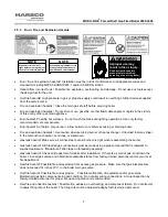
Page 6: ... personnel traffic with adequate working space adequate clearances proper ventilation and lighting with a structure sufficiently strong and rigid to support the weight of the boiler all piping and accessories 2 5 1 Electrical Hazards Shock hazard Properly lockout tagout the electrical service and all other energy sources before working on or near the machine Shock hazard Boiler is not rated for wa...

Page 7: ...sion hazards Use caution when servicing burner or heat exchanger Unburned fuel may linger in the combustion chamber vent lines or elsewhere Gas leak hazard Make sure all connections to main burner are tight when reassembling the burner Gas leak hazard All threaded gas connections must be made using a pipe compound that is resistant to liquefied petroleum Do not use Teflon tape on threaded gas pipi...

Page 8: ...olonged period of inactivity Do not operate boiler with faulty relief valve 2 5 5 General Hazards Tripping hazard Do not install piping on floor surfaces Maintain clear path around boiler Slip and fall hazard Use drip pan to catch water while draining the boiler Maintain dry floor surfaces Slip and fall hazard Through the wall vents shall not terminate over public walkways or over an area where co...

Page 9: ...Canada the equipment shall be installed in accordance with the current Installation Code for Gas Burning Appliances and Equipment CAN CSA B149 1 and applicable Provincial Regulations for the class which should be carefully followed in all cases Authorities having jurisdiction should be consulted before installations are made Where required by local codes the installation must conform to American S...

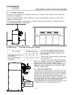
Page 10: ...ents Service access need be only on one side of a boiler or row of boilers Boilers may be installed immediately adjacent to each other However Harsco Industrial Patterson Kelley recommends this clearance between each boiler when there is insufficient access at the rear to allow for service and adjustment 3 4 ELECTRICAL CONNECTIONS All field wiring connections for power and controls are in the junc...

Page 11: ...to HV14 The neutral for this circuit is provided on HV 6 DHW Pump Relay w Delay Off This output is enabled when there is a call for DHW When the call for heat is removed the output remains enabled for a period of time This output provides 120VAC 0 5Amp service to HV15 The neutral for this circuit is provided on HV 7 Circ Pump Relay w Delay Off This output is enabled when there is a call for heat W...

Page 12: ... to LV14 Analog Input Remote signal for controlling the boiler The boiler can be operated in a remote setpoint or a remote firing rate control mode Input 0 10VDC signal only The temperature control must be programmed to run with the analog input MODBUS LV19 and LV20 are used for connecting a MODBUS building management system See the ENVI Control Advanced Users Guide for more information Cascade LV...

Page 13: ...nt Category III An appliance that operates with a positive vent static pressure and with a vent temperature that avoids excessive condensate production in the vent Category IV An appliance that operates with a positive vent static pressure and with a vent temperature that may cause excessive condensate production in the vent Direct Vent An appliance that is constructed and installed so that all ai...

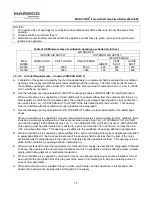
Page 14: ...ing should commence less than 12 inches above the floor and the other less than 12 inches below the ceiling The minimum dimension of air openings shall be 3 inches When rooms are on different floors each opening shall have an area equal to 2 square inches for each 1000 Btu hr 4400 mm2 kW of installed appliance input capacity When combustion air is supplied from outside the building the boiler room...

Page 15: ... A C Use the following opening calculation for P K THERMIFIC boilers or other natural draft or fan assist appli ances When combustion air is supplied for natural or fan assisted burners by natural airflow from the outdoors there shall be a permanent opening with a cross sectional area not less than 1 sq in 7000 Btu Hr 321 mm2 kW up to and including 1 000 000 Btu Hr plus 1 sq in 14 000 Btu Hr 155 m...

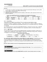
Page 16: ...s Code or CAN CSA B149 1 the Natural Gas and Propane Installation Code or applicable provisions of the local building codes 3 5 3 1 VENT SIZING The vent must be sized in accordance with the ASHRAE Systems and Equipment handbook Chapter 30 or ac cording to the vent manufacturer s recommendations When using manufactured venting systems consult your vent supplier for correct sizing and structural sup...

Page 17: ...at least 4 ft below 4 ft horizontally from or 1 ft above any door operable win dow or gravity inlet into any building The bottom of the vent terminal shall be at least 12 in above grade or highest expected snow line if applicable Through the wall terminations shall not terminate over public walkways or over an area where condensate or vapor could create a nuisance or hazard or could be detrimental...

Page 18: ...ow spots where condensate can collect Structural supports must be connected to building elements of sufficient strength to withstand the weight of the vent system and any bending forces imposed by the venting system This boiler has 10 OD connections for the vent If venting design permits this connection may be reduced to 8 diameter The connection from the boiler to the vent should be made using an...

Page 19: ...ucture within ten 10 feet of the vent This is illustrated in the following diagram Additionally the boiler vent shall terminate at least 3 ft above a forced air inlet located within 10 ft Building Sidewall See 3 6 6 for termination details Pitch Towards Boiler per foot min Boiler Outlet 10 OD Tee w Drain Boiler Condensate Drain stainless steel or silicone tubing Stack Drain w Trap 4 min height ...

Page 20: ...xhaust gas through idle boilers 3 5 5 Sealed Combustion Direct Vent Systems The MODU FIRE Forced Draft boilers are also certified for operation with a sealed combustion air and pressur ized venting system Such a system employs a sealed combustion air intake duct leading from outdoors and a sealed exhaust vent terminating outdoors Air flow through the system is maintained by the combustion air fan ...

Page 21: ...the common venting system properly vents when tested as outlined above return doors windows exhaust fans fireplace dampers and any other gas burning appliance to their previous conditions of use Any improper operation of the common venting system should be corrected so the installation conforms with the National Fuel Gas Code NFPA 54 ANSI Z223 1 and CAN CSA B149 1 Installation Code When resizing a...

Page 22: ... Fuel Gas Code NFPA 54 ANSI Z223 1 latest edition and any other local codes which may apply In Canada please refer to CAN CSA B149 1 Pipe Capacity for Natural Gas NOTICE See Pipe Capacity for Natural Gas chart for required pipe size based on overall length of pipe from meter plus equivalent length of all fittings Approximate sizing may be based on 1 cubic foot of natural gas per 1 000 Btu per hour...

Page 23: ...erature may be achieved through a combination of primary and secondary flow loops Multiple zones and pumps may result in different flow rates at different times Consideration must be given to all possible conditions and their consequences 3 7 1 2 Piping with Refrigeration Machines When used with a refrigeration system the boiler shall be installed so that chilled medium is piped in parallel with t...

Page 24: ...UTLET and must be connected as the hot water supply to the system The left connection is the boiler INLET and must be used for the cold water return from the system Piping must be installed such that no piping stresses are transmitted to the boiler The boiler shall not be used as a pipe anchor 3 7 3 Boiler Water Piping by Installer 3 7 3 1 Strainer To avoid possible contamination of the boiler wit...

Page 25: ...ng of the boiler water only not the entire system Draining of the system through the boiler will result in depositing sediment from the system in the boiler which will result in poor heat transfer characteristics of the boiler and early boiler failure 3 7 4 Flushing and Filling 3 7 4 1 Flushing the System Before filling the boiler flush the system to remove the debris Clean and flush old piping th...

Page 26: ...tion has been made pressure tested for leakage and the line purged of air See section 3 6 3 Water connections are complete and the boiler and system have been filled and purged of air See section 3 7 4 The boiler must be connected to a 240 volt 60 Hz 1 Ph power source with proper polarity a dedicated machinery ground and provided with a disconnect having adequate overload protection See section 3 ...

Page 27: ...ammer will recognize a Flame Failure condition and go to a lockout mode Lockout will require manual reset of the flame safeguard After completing this test turn off the boiler and reconnect the wires to the main gas valve 3 10 2 Test of Low Water Cut off The boiler is furnished with a flow switch type low water cut off in the outlet nozzle Test as follows 1 Turn boiler and then system pump off 2 T...

Page 28: ...he boiler as well as maintaining temperature of the supply water The temperature control portion modulates the boiler to maintain the desired outlet temperature based on the selected operating configuration 3 11 1 Initial Adjustments The ENVI control uses a Liquid Crystal Display LCD as a method of supplying information The LCD is used to setup and monitor system operation by means of six push but...

Page 29: ...e ENVI Control Getting Started Guide contains additional information regarding the operation of this control NOTICE Changing parameters requires an understanding of the parameters and the functionality of the boiler The boiler may not function properly if parameters are changed from the factory values 3 12 COMBUSTION ADJUSTMENT There is no required start up or field adjustments for air flow contro...

Page 30: ...st test mode allows the service technician to hold the boiler in high or low fire during operation so that the combustion adjustment can be performed Press the UP or DOWN button to select BURNER ON or BURNER OFF press ENTER Then press the UP button followed by ENTER to select HIGH or DOWN followed by ENTER to select LOW operation The second test mode checks the fan rate with the burner off at high...

Page 31: ...MODU FIRE Forced Draft Gas Fired Boiler 2500 3000 31 Ratio V Adjust at Hi Fire Bias N Adjust at Low Fire ...

Page 32: ...tem controls get power Open the manual gas supply valves Make sure the system is filled with water and turn on the circulation pump 2 Reset Switches Press the reset button on both the high gas and low gas pressure switches if the gas supply had previously been turned off Press the control reset button after a safety lockout 3 Turn on the power switch The blower will purge briefly as the electronic...

Page 33: ...k daily to be sure that the boiler area is free and clear of any combustible materials including flammable vapors and liquids 5 1 2 Weekly Observe the conditions of the main flame A normal high fire flame shows an orange screen with a blue halo In Low fire the burner should display a reddish orange glow However do not attempt to adjust the flame by eye Correct air adjustment is essential for the e...

Page 34: ... and its parts If there is evidence of deterioration or corrosion replace immediately 2 Inspect combustion chamber To access the heat exchanger remove the front door and the front inner wrapper Note any signs of deterioration Examine the gasket and replace if necessary using a Harsco Industrial Patterson Kelley gasket kit only 3 Inspect and clean heat exchanger Wash the copper tubes with water and...

Page 35: ...wer while leaving the piping attached Lift the assembled air gas mixer and piping out of the boiler and place it on the rear boiler water piping Do not disconnect the wires to the gas pressure switch 6 Remove the blower and gasket from the boiler Clean the blower vanes Do not disassemble the blower motor or aluminum housing 7 CAREFULLY remove the ignition assembly from the boiler Check the gap bet...

Page 36: ... If adjustment is required refer to section 3 14 1 5 3 REMOVING THE HEAT EXCHANGER Heat Exchanger is heavy and may cause injury if improperly handled Removal of the heat exchanger should be performed only by knowledgeable and experienced personnel 5 4 AFTER ALL REPAIRS OR MAINTENANCE 1 Follow Pre Start Check List Section 3 10 and all Safety Checks Section 3 11 and verify proper operation 2 Fire th...

Page 37: ... Flame must be detected at T 6 seconds Ignition Sequence Timing 0 1 2 3 4 5 6 7 Spark Gas Valve Flame Detection Seconds Fan Flame must be detected at T 6 seconds Ignition Sequence Timing NOTICE Once the boiler begins the ignition sequence the firing sequence will continue until main flame is reached regardless of heat request The sequence can be interrupted by turning the power switch off 5 6 TROU...

Page 38: ...hrough the boiler Check the hoses leading to the air switches Verify proper blower operation An air switch error does not necessarily mean that the air switch is defective When AIR SWITCH NOT OPEN is shown on the display check that the air switch is open when the fan is off Check that there is no air flow through the boiler when the fan is off When AIR SWITCH NOT CLOSE is shown on the display chec...

Page 39: ...e unit must be isolated by turning off the main gas supply line Qualified and knowledgeable service personnel must be called to evaluate and repair replace the failed parts A comprehensive listing of the locking and blocking error codes is provided below NOTICE When an Internal Software Error occurs the failure is internal to the ENVI boiler control and re placement of the ENVI control is required...

Page 40: ...oftware error A16 20 MS XLR ERROR 22 Internal software error A18 STACK ERROR 19 Internal software error A19 FLAME OUT TOO LATE ERROR 20 Flame still present 10 sec after closing the gas valve A20 FLAME ERROR I 21 Flame detected just before gas valve opened A30 HIGH GAS PRESSURE ERROR 32 Gas pressure is to high A31 LOW GAS PRESSURE ERROR 31 Gas pressure is to low A32 41MS ERROR 23 Internal software ...

Page 41: ...R 45 No earth ground connected or internal hardware error E23 NET FREQ ERROR 47 Main supply voltage frequency differs more than 2 from 60HZ E24 FAULTY EARTH ERROR 48 Faulty earth ground to boiler E30 FLUE GAS ERROR 39 Flue gas sensor is above setpoint plus differential E32 RETURN TEMP ERROR 42 Return temperature is above 90 degrees E34 BLOCKED FLUE ERROR 41 Flue gas outlet is restricted or blocked...

Page 42: ...nt All control components are engineered for safety and are designed to work in unison with each of the other components Use of non factory authorized replacement parts would jeopardize the functionality of the safety features as well as the performance of the boiler Technical information is also available at the above number or at the Harsco Industrial Patterson Kelley website www harscopk com Wh...

Page 43: ...ump Relay Neutral Line for Circ Pump Relay 9 Damper Relay Neutral Line for Damper Relay 10 G 208 240 VAC Boiler Ground 11 G 208 240 VAC Boiler Ground 12 120VAC Switched Output 120VAC Output when boiler power is switched ON 13 120VAC Switched Output 120VAC Output when boiler power is switched ON 14 3 Way Valve 120 VAC 3 Way Valve De energized when DHW enabled Valve is Normally set to Heating Loop 1...

Page 44: ... External Limit Contact Closure DO NOT ENERGIZE 6 7 Outdoor Temp Sensor Outdoor Temperature Sensor Circuit 8 9 DHW Stat or Sensor Domestic Hot Water Thermostat contact closure or Temperature Sensor 10 11 Header Temp Sensor Header Temperature Sensor 12 13 DHW Flow Switch DHW Flow Switch contact closure 14 15 0 10V Analog Input 0 10VDC Remote Control Input 16 0V Analog Input 0VDC Remote Control Comm...

Page 45: ...MODU FIRE Forced Draft Gas Fired Boiler 2500 3000 45 6 1 3 Wiring Schematic ...

Page 46: ...4 Control Panel Components Mark Description 1 Air Switch 2 Circuit Breaker 3 On Off Switch 4 ENVI Control Display 5 High Limit 6 ENVI Control Main Board 7 ENVI Control Interface Board 8 Blower Fuses 9 Ignition Transformer ENVI Control Panel 9 3 1 6 7 4 5 8 2 ...

Page 47: ...MODU FIRE Forced Draft Gas Fired Boiler 2500 3000 47 6 1 5 Control Panel Wiring Menu Back Enter Up Down Reset Alarm Flame Enable ...

Page 48: ...MODU FIRE Forced Draft Gas Fired Boiler 2500 3000 48 6 1 6 Rear Junction Box ...

Page 49: ...MODU FIRE Forced Draft Gas Fired Boiler 2500 3000 49 6 1 7 Customer Connections ...

Page 50: ...0 3000 50 6 1 8 Gas Train Mark Description 1 Main Gas Shutoff Valve 2 Low Gas Pressure Switch 3 Leak Test Ports 4 Automatic Dual Gas Valve 5 Solenoid Coils 6 High Gas Pressure Switch 7 Secondary Gas Shutoff Valve 8 Air Gas Mixer 3 2 8 1 4 5 7 6 ...

Page 51: ...mbly Mark Description 1 Burner 2 Burner Gasket 3 Mounting Plate 4 Transition Piece Gasket 5 Transition Piece 6 Blower Gasket 7 Blower w Motor 8 Air Gas Mixer Gasket 9 Air Gas Mixer 10 Ignition Gasket 11 Ignition Electrode 12 UV Scanner 13 Backpressure Switch 11 13 12 1 2 3 4 7 10 5 6 8 9 ...

Page 52: ...MODU FIRE Forced Draft Gas Fired Boiler 2500 3000 52 6 1 10 Heat Exchanger and Combustion Chamber Mark Description 1 Front Wrapper 2 Heat Exchanger 3 Gasket Set 4 Removable Top Head 4 3 2 1 ...

Page 53: ... 2500 3000 53 6 1 11 Cabinet Assembly Mark Description 1 Front Door 2 Side Covers 3 Top Cover 4 Control Panel 5 Relief Valve 6 Flow Switch 7 Low Water Cutoff Switch optional 8 Air Inlet Assembly 9 Electrical Junction Box 1 2 3 5 6 7 8 9 2 4 ...

Page 54: ...ar application F Any failure resulting from misuse modification not authorized by Seller in writing improper installation or lack of or im proper maintenance G Equipment furnished by the owner either mounted or unmounted or when contracted for by the owner to be installed or handled H Leakage or other malfunction caused by 1 Defective installations in general and specifically any installation whic...

Page 55: ...tack exits boiler High Low w c High Inlet Gas w c w c w c Low Oxygen O2 10 Electrical Supply Power L1 to L2 Volts Carbon Dioxide CO2 L1 to N Volts Carbon Monoxide CO ppm ppm Less than 1 volt between neutral and ground YES or NO Stack Temperature net F F 11 Total Cycles Main Flame Signal Yes No Yes No 12 Total Hours Inlet Air Temperature F F 13 Any Faults Describe with code time and description 14 ...

Page 56: ...MODU FIRE Forced Draft Gas Fired Boiler 2500 3000 56 ...

Reviews: