
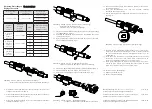
09 10 004 3001 / 99.00
Schirmelement
Shielding element
Élément de blindage
Kontaktträger
Contact holder
Support de contact
Montagehilfe
Assembly aid
Aide d’ assemblage
Isolierkörper
Insulation body
Corps isolant
Schirmhülse
Shielding sleeve
Manchon de blindage
Kabelbinder
Cable tie
Attache de câble
Gehäuse
Hood / housing
Capot / embase
Kabeladapter*
Cable adapter*
Adaptateur de câble*
Montageanleitung
·
Assembly instructions
Assembly instructions
·
Schéma d’assemblage
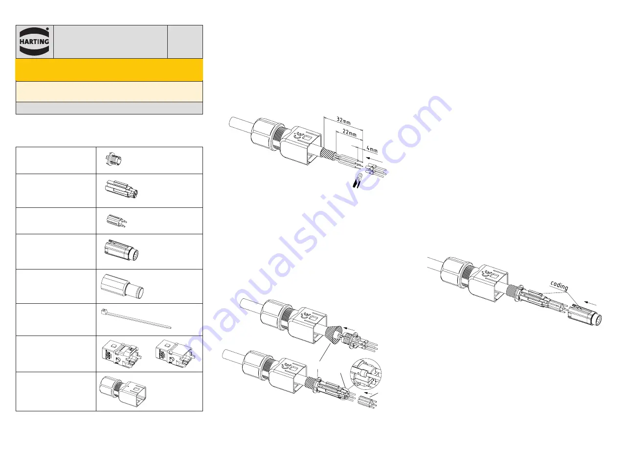
1. Schieben Sie den Kabeladapter schrittweise auf das Kabel. Ein Kabel-
durchmesser zwischen 5,7 und 10 mm ist erforderlich.
1.
Slide the cable adapter stepwise onto the cable. A cable
diameter between 5.7 and 10 mm is required.
1. Glissez l’adaptateur de câble sur le câble en plusieurs étapes. Utilisez
un câble d’un diamètre compris entre 5,7 et 10 mm.
Abbildung ·
Figure
·
Figure
1
:
Abisolierlängen /
Stripping lengths /
Longueurs à dénuder
2. Isolieren Sie den Kabelmantel ab wie in der Abb. 1 beschrieben.
2. Remove the cable sheath as indicated by Figure 1.
2. Denudez la gaine du câble comme indiqué dans le dessin, Figure 1.
3.
Entfernen Sie die Aderisolierung und crimpen Sie die Kontakte (Abb. 1).
3. Remove the wire insulation and terminate the crimp contacts
(Fig. 1).
3. Dégagez l’isolant des fils et sertissez les contacts (Fig. 1).
⑧
⑥
⑦
Abbildung ·
Figures
·
Figures 2 & 3 : S
chirmgeflecht anlegen /
Spreading
the shielding braid
/
Mettre en place la tresse de blindage
4. Schieben Sie das Schirmelement unter das Schirmgeflecht (Abb. 2 & 3).
4. Push the shielding element under the shielding braid (Fig. 2 & 3).
4. Poussez l’élément de blindage sous la tresse de blindage (Fig. 2 & 3).
5. Legen Sie das Schirmgeflecht gleichmäßig auf das Schirmelement
auf (Abb. 3,
⑥
).
5. Spread the shielding braid evenly over the shielding element
(Figure 3,
⑥
).
5. Posez la tresse de blindage à plat sur l
’
élément de blindage (Fig. 3,
⑥
).
6. Setzen Sie die Kontakte in die seitlichen Kavitäten des Kontaktträgers
ein (Abb. 3,
⑦
). Verwenden Sie zur Kodierung die farbigen Kennzeich-
nungen auf dem Kontaktträger.
6.
Insert the contacts into the lateral cavities of the contact
holder (Fig. 3,
⑦
). For assignment use the color identification
marks on the contact holder.
6
Insérez les contacts dans les cavités latérales du support de contact
(Fig. 3,
⑦
). Pour appliquer une codage, utilisez les marques d’identifica-
tion de couleur sur le support de contacts.
7. Stecken Sie die Montagehilfe auf die Kontakte (Abb. 3,
⑧
).
7. Put the assembly aid onto the contacts (Fig. 3,
⑧
).
7. Placez l’aide d’assemblage sur les contacts (Fig. 3,
⑧
).
Abbildung ·
Figure
·
Figure 4 :
Kodierung Kontaktträger und Isolierkörper /
Coding contact holder and insulation body
/
Codage du sup-
port de contact et isolant
8. Schieben Sie den Isolierkörper auf den Kontakthalter, bis er einrastet
(Abb. 4).
8. Slide the insulation body on the contact holder, until it clicks
into place (Fig. 4).
8. Glissez l
’
isolant sur le support de contact, jusqu’à ce qu’il s’enclenche
en place (Fig. 4).
HARTING Electric GmbH & Co. KG |
Wilhelm-Harting-Straße 1 | D-32339 Espelkamp
Fon: +49 57 72 47-97100 | Fax: +49 57 72 47-124
Internet: www.HARTING.com |
E-Mail: electric@HARTING.com
Deutsch
E
nglish
Français
Han
®
1 A D-coded, male
Artikelnummern ·
Part numbers
Part numbers
·
Références
09 10 004 3001 / 09 10 004 3006
www.HARTING.com
Inhalt
·
Content
Content
·
Contenu
* Nicht Teil der Lieferung
/ Not within scope of delivery /
N’est pas compris dans
la livraison


