background image

Model Sirius-PJ2


Machine Codes: 

Y076/Y077/Y078


Field Service Manual 

June, 2015 

Summary of Contents for Sirius-PJ2

Page 1: ...Model Sirius PJ2 Machine Codes Y076 Y077 Y078 Field Service Manual June 2015 ...

Page 2: ......

Page 3: ...ng servicing such as the cabinet chassis and parts are labelled with individual safety instructions Carefully comply with these instructions and all precautions in the instruction manual 2 BE CAREFUL OF ELECTRIC SHOCK The chassis carries an AC voltage If you touch the chassis while it is still live you will get a severe shock If you think the chassis is live use an isolating transformer or gloves ...

Page 4: ...d to their original positions Also examine if the serviced sections and peripheral areas have suffered from any damage as a result of servicing In addition check the insulation between external metallic parts and the blades of wall outlet plugs This examination is indispensable in confirming complete establishment of safety Insulation check Pull out the plug from the wall outlet to disconnect the ...

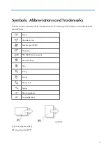
Page 5: ...eviations The meaning of those symbols and abbreviations are as follows Screw Shoulder screw Black screw TCRU Connector FFC Flat Film Connector Harness clamp Clip E ring C ring Timing belt Spring SEF Short edge feed LEF Long edge feed A Short edge feed SEF B Long edge feed LEF 3 ...

Page 6: ...ed States other countries or both Crestron is a registered trademark of Crestron Electronics Inc Microsoft and Windows are registered trademarks or trademarks of Microsoft Corporation in the United States and or other countries The proper names of the Windows operating systems are as follows The product names of Windows 7 are as follows Microsoft Windows 7 Home Premium Microsoft Windows 7 Professi...

Page 7: ... the Remote Controller 18 2 Installation Installation Requirements 23 Fire and Shock Precautions 23 Caution on Handling the Optional Lens 25 Lamp Replacement 25 About High Altitude Mode 26 3 Replacement and Adjustment Replaceable Part Hierarchy 27 Special Tools 28 Parts Replacement 31 Zoom Lens 31 Lamp Unit 31 Filters 32 Top Cover 33 PCB Key Pad 34 Front Cover 35 PCB SCAP 36 PCB LED 37 Lens Shift ...

Page 8: ... Integrator 1 57 Integrator 2 57 IRIS Unit 58 OPT Base 59 Thermostat 60 PCB Lamp Interlock 61 PSU Fan 62 Power Supply Ballast 64 Power Supply DC 64 Replacement of Optical Parts 66 Polarizer B 66 Polarizer G 67 Polarizer R 67 Optical Parts Adjustment 68 Adjusting and fixing parts 68 Adjustment of the optical axis Shadow adjustment 69 Adjustment of the polarization plate Contrast adjustment 76 Elect...

Page 9: ...ellaneous 97 Procedure for writing of a serial number and a model number 99 Software installation 99 Writing of a serial number and a model number 99 Data readout 101 PC control software for service 101 Outline software descriptions 101 Equipment to be used and environment 102 Software installation procedures 102 Repair and adjustment procedures 102 Error messages 111 4 System Maintenance Firmware...

Page 10: ...pert Mode 132 Additional functions 132 Menus and functions to be added by the Expert Mode 132 Menus and functions to be added by the Service Mode 134 How to withdraw from the mode 137 Troubleshooting Guide 138 Operation Check for the Main Board 138 For Video 139 For Audio 140 For Multi Media 141 Operation Check for the PCB Network 141 Error Log 142 Error Log Screen Image 142 Displaying the error l...

Page 11: ...rror Log Page2 Display 147 TEMP Columns 147 Lamp Filter Clear Count 148 Lamp ON OFF Count 148 Projector Hours Used 148 Iris Current Past 148 Lamp Voltage Indicated exceeding the Service Power 148 Contents of Error Log Page3 Display 149 Contents of Error Log Reset Display 150 ALL DATA 150 9 ...

Page 12: ...10 ...

Page 13: ...1 Product Information Specifications See Appendices for the following information General Specifications 11 ...

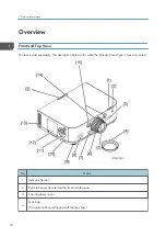
Page 14: ...The description below is for when the Standard Lens Type 1 lens is mounted No Name 1 Indicator Section 2 Remote Sensor located on the front and the rear 3 Securing lever cover 4 Lens Cap The optional lens is shipped with the lens cap 1 Product Information 12 ...

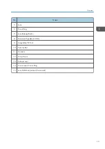
Page 15: ... 6 Focus Ring 7 Lens Release Button 8 Monaural Speaker 10 W 9 Adjustable Tilt Foot 10 Security Bar 11 Controls 12 Lamp Cover 13 Exhaust vent 14 Zoom Lever Zoom Ring 15 Lens Shift Dial vertical horizontal Overview 13 ...

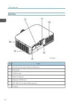
Page 16: ...me 1 Remote Sensor located on the front and the rear 2 Exhaust vent 3 AC IN Terminal 4 Built in Security Slot 5 Intake vent Filter Cover 6 USB LAN Port located inside the projector 7 Terminals 1 Product Information 14 ...

Page 17: ...ashes when the button has been pressed while the projector is in key lock mode or the projector has a problem 3 LAMP Indicator Indicates the lamp status and replacement grace period 4 TEMP Indicator Lights up in orange when the surrounding temperature is high 5 Power Button Turns the projector on and then off standby To turn the projector off standby then press the Power button one time When the c...

Page 18: ...tly displayed on screen menu Applies the selected item while the confirmation message is displayed 10 MENU Button Displays an on screen menu for setting or adjusting a variety of items 11 INPUT Button Selects the signal input Pressing the INPUT button briefly displays the INPUT screen Pressing the INPUT button for one second or longer checks the signal inputs automatically in the following order H...

Page 19: ...R IN Component Input Connector Mini D Sub 15 Pin 7 COMPUTER AUDIO IN Mini Jack Stereo Mini 8 BNC AUDIO IN Mini Jack Stereo Mini 9 REMOTE Connector Stereo Mini not available on this series of projectors 10 PC CONTROL Port D Sub 9 Pin 11 BNC Y C Input Connector BNC 2 12 BNC CV Input Connector BNC 1 13 3D SYNC Connector Mini DIN 4 Pin 14 AUDIO OUT Mini Jack Stereo Mini 15 USB A Port Type A Overview 1...

Page 20: ...No Name 16 Ethernet Port RJ 45 Part Names of the Remote Controller 1 Product Information 18 ...

Page 21: ...r when using the multi screen function 7 AUTO ADJ Button Auto adjustment for Computer Analog RGB HDMI 1 HDMI 2 DisplayPort projecting 8 DisplayPort Button Selects the DisplayPort input 9 BNC CV Button Selects BNC CV Input Composite Video Signal 10 BNC Y C Button Selects BNC Y C Input S Video Signal 11 USB A Button Selects the viewer 12 Numeric Keypad Button CLEAR Button The remote controller that ...

Page 22: ...tors 25 DISPLAY Button Displays the DISPLAY menu to set adjust picture display 26 COLOR Button Corrects the color for all signals Adjusts the tone for the colors red green blue yellow magenta and cyan 27 PICTURE Button Displays the PICTURE menu for adjusting the projected image 28 SHUTTER Button not available on this series of projectors 29 VOL FOCUS Button Adjusts the volume of the internal speak...

Page 23: ...al input it projects the input signal 40 PIP Button Press to project the sub screen inside the main display and to display the menu for selecting the input terminal for the sub screen 41 PBP POP Button Press to project the main screen and sub screen side by side and to display the menu for selecting the input terminal for the sub screen 42 Edge Blend Button Press this button to make the edges boun...

Page 24: ...1 Product Information 22 ...

Page 25: ... heat inside the projector Allow at least 4 inches 10cm of space between the projector and a wall Do not try to touch the ventilation outlet on the left front when seen from the front as it can become heated while the projector is turned on and immediately after the projector is turned off Parts of the projector may become temporarily heated if the projector is turned off with the Power button or ...

Page 26: ...ver the power cord with soft materials such as rugs Do not heat the power cord Do not handle the power plug with wet hands Turn off the projector unplug the power cord and have the projector serviced by qualified service personnel under the following conditions When the power cord or plug is damaged or frayed If liquid has been spilled into the projector or if it has been exposed to rain or water ...

Page 27: ...l Lens When shipping the projector with the lens remove the lens before shipping the projector Always attach the dust cap to the lens whenever it is not mounted on the projector The lens and the lens shift mechanism may encounter damage caused by improper handling during transportation Do not hold the lens part when carrying the projector Doing so could cause the focus ring to rotate resulting in ...

Page 28: ...t be lit Generally this problem tends to occur when the power is forcibly turned off Example Disconnecting the AC cable while the power is on power outage occurring breaker being thrown About High Altitude Mode Set FAN MODE to HIGH ALTITUDE when using the projector at altitudes approximately 5500 feet 1700 meters or higher Using the projector at altitudes approximately 5500 feet 1700 meters or hig...

Page 29: ... below shows what parts must be removed to access each replaceable part in the projector The parts on the first level e g Lamp cover are accessible without removing any other parts The more levels down that a part is the more parts must be removed in order to access it 27 ...

Page 30: ...6181N 3 Y0785214 Extension connector 57P For LCD PANEL For PJ WX6181N PJ X6181N 3 Y0785215 Extension connector PWB 57P For LCD PANEL For PJ WX6181N PJ X6181N 3 Y0785216 Extension connector 18P For Power supply PS UNIT POPS 600mm 1 Y0135211 Extension connector PWB 18P For Power supply PS UNIT 1 Y0135212 Extension connector 5P For Power supply BS UNIT POLM 900mm 1 Y0135207 Extension connector PWB 5P...

Page 31: ...0135203 Extension connector PWB 3P For FAN 4 Y0135204 Extension connector 2P For THERMISTOR POTH1 POTH3 900mm 2 Y0135201 Extension connector PWB 2P For THERMISTOR 2 Y0135202 IRIS UNIT 1 For IRIS UNIT POMO 1 Y0783111 SPACER FL T0 1 PB52 2 Spacer for FL adjustment this is one of the optical axis adjustments Y0133120 SPACER FL T0 2 PB52 2 Y0133121 SPACER FL T0 3 PB52 2 Y0133122 SPACER FL T0 5 PB52 2 ...

Page 32: ...ke out from the projector when you perform the optical parts adjustment 2 The numbers such as 0 1 shows the thickness 0 1 means 0 1mm 0 5 represents the thickness of 0 5mm Cautions How to install the FFC cable Photo seen from above Insert the FFC cable in the relevant connector on the PWB Let the embossed part framed part in blue shown below fall down in the direction of the red arrow The embossed...

Page 33: ...Parts Replacement Zoom Lens 1 Zoom lens Remove in the order 1 to 3 Lamp Unit 1 Loosen the screw and remove the Lamp cover A 1 2 Loosen the screws and remove the Lamp unit A 2 Parts Replacement 31 ...

Page 34: ...Filters 1 Remove the Filter cover A 2 Remove the Filters A 3 Replacement and Adjustment 32 ...

Page 35: ...he top cover should be done with utmost care 1 Remove the Lamp unit page 31 2 Remove the Filters page 32 3 Loosen the screw 4 Top cover A 11 B It might be difficult to remove the cover due to projections inside the chassis Be careful not to damage the cover or other parts when removing the cover from inside the chassis C There is a cable connecting the Top Cover to the main unit Exercise care when...

Page 36: ...5 Disconnect the cable 1 PCB Key Pad 1 Top cover page 33 3 Replacement and Adjustment 34 ...

Page 37: ...2 Remove the Holder A 2 3 Remove the PCB Key Pad A 2 Front Cover 1 Top cover page 33 Parts Replacement 35 ...

Page 38: ...2 Front Cover A 4 3 Remove the two connectors 2 PCB SCAP 1 Front Cover page 35 3 Replacement and Adjustment 36 ...

Page 39: ...2 Remove the PCB SCAP A 1 1 PCB LED 1 Front Cover page 35 2 Remove the PCB LED with holder A 1 Parts Replacement 37 ...

Page 40: ...3 Release the tabs to remove the holder as below 4 Remove the connector 1 3 Replacement and Adjustment 38 ...

Page 41: ...Lens Shift Dial 1 Remove the Lens Shift Dial A and spring Rear Panel 1 Top cover page 33 Parts Replacement 39 ...

Page 42: ...2 Rear panel A 3 PCB Remote Controller 1 Top cover page 33 2 Remove the PCB Remote Controller A 1 1 USB Network Board 1 Top cover page 33 3 Replacement and Adjustment 40 ...

Page 43: ...the PCB Main Ass y involves making adjustments to the software refer to Electrical Adjustment Before removing the Ass y be sure to read or copy all data 1 Rear panel page 39 2 Remove the PCB Remote Controller page 40 3 Remove the bracket A 9 Parts Replacement 41 ...

Page 44: ...4 Remove the PCB Main Ass y and PCB Network unit 5 16 5 Remove the PCB Network page 43 6 Remove the bracket A and cable B 10 3 Replacement and Adjustment 42 ...

Page 45: ... 2 Remove the PCB Network A 5 1 A small ground plate assembly is fixed together with the PCB Network Be very careful not to lose this assembly when removing the PCB Network because the assembly is to be used again when replacing a new PCB Network PCB EX 1 Top cover page 33 2 Remove the bracket Parts Replacement 43 ...

Page 46: ...3 Remove the PCB EX 2 7 Lamp Temp Sensor 1 Top cover page 33 2 Remove the Lamp Temp Sensor A 1 1 Exhaust Fan 1 Top cover page 33 2 Remove the Lamp Temp Sensor page 44 3 Replacement and Adjustment 44 ...

Page 47: ...the Fan Unit 3 2 4 Remove the Exhaust fan 2 When installing the fan on the holder make sure to install it in the correct orientation Speaker 1 Front Cover page 35 2 Remove the PCB EX page 43 Parts Replacement 45 ...

Page 48: ...3 Remove the Speaker A 2 Lamp Fan Upper 1 Remove the PCB EX page 43 2 Remove the bracket A 4 1 3 Replacement and Adjustment 46 ...

Page 49: ...pper with holder A 2 4 Remove the holder of the Lamp Fan upper 2 When installing the fan on the holder make sure to install it in the correct orientation Lamp Fan Lower 1 Remove the Lamp Fan Upper page 46 Parts Replacement 47 ...

Page 50: ...re to install it in the correct orientation Reflector Fan 1 Remove the PCB EX page 43 2 Remove the bracket A 4 1 3 Remove the Fan Unit A 2 B When assembling the projector route the PCB Lamp Interlock cable along the space beside the Lamp Fan Unit 3 Replacement and Adjustment 48 ...

Page 51: ...Fan A 2 When installing the fan on the holder make sure to install it in the correct orientation G LCD Fan 1 Front Cover page 35 2 Remove the USB Network Board page 40 3 Remove the PCB Main Ass y page 41 Parts Replacement 49 ...

Page 52: ...4 Remove the bracket A 5 Remove the G LCD Fan A 2 6 Remove the cushion A 3 Replacement and Adjustment 50 ...

Page 53: ... R LCD Fan have the same number of pins Make sure that you connect appropriate connector when installing them R LCD Fan 1 Front Cover page 35 2 Remove the USB Network Board page 40 3 Remove the PCB Main Ass y page 41 4 Remove the bracket A Parts Replacement 51 ...

Page 54: ...5 Remove the Duct Cover A 3 6 Remove the Duct Base A 3 3 Replacement and Adjustment 52 ...

Page 55: ...n Both the connector A for G LCD Fan and the connector B for R LCD Fan have the same number of pins Make sure that you connect appropriate connector when installing them Internal Temp Sensor 1 R LCD Fan page 51 2 Remove the Internal Temp Sensor A B When assembling the projector route the cable through the notch Parts Replacement 53 ...

Page 56: ...B LCD Fan 1 Remove the USB Network Board page 40 2 Remove the PCB Main Ass y page 41 3 Remove the bracket A 3 Replacement and Adjustment 54 ...

Page 57: ...installing the fan on the holder make sure to install it in the correct orientation PS Converter When removing or installing the IRIS Unit be careful not to damage the Integrator 1 Remove the USB Network Board page 40 2 Remove the PCB Main Ass y page 41 Parts Replacement 55 ...

Page 58: ...3 Remove the bracket A 4 Remove the Integrator unit A 2 5 Remove the PS Converter A 2 3 Replacement and Adjustment 56 ...

Page 59: ...nverter page 55 2 Remove the Integrator 1 A 4 When mounting Integrator 1 press it up against the area shown in the lower right of the figure then screw it into place Integrator 2 Carefully handle the removed Integrator to avoid damaging it 1 Remove the PS Converter page 55 Parts Replacement 57 ...

Page 60: ...A 4 When mounting Integrator 1 press it up against the area shown in the lower left of the figure then screw it into place IRIS Unit 1 Remove the Integrator unit page 55 2 Remove the IRIS unit A 2 3 Replacement and Adjustment 58 ...

Page 61: ...oftware refer to Electrical Adjustment and the optical axis refer to Optical Parts Adjustment 1 Front Cover page 35 2 Remove the USB Network Board page 40 3 Remove the PCB Main Ass y page 41 4 Remove the PCB EX page 43 5 Remove the bracket A 3 Parts Replacement 59 ...

Page 62: ...6 Remove the OPT Base A 4 Thermostat 1 Remove the Exhaust Fan unit page 44 2 Remove the barrier and guard A 1 3 Replacement and Adjustment 60 ...

Page 63: ...rint side of the thermostat face up PCB Lamp Interlock 1 Front Cover page 35 2 Remove the Exhaust Fan page 44 3 Remove the Lamp Fan unit page 46 4 Remove the Reflector Fan page 48 5 Remove the G and R LCD Fan unit page 49 6 Remove the B LCD Fan page 54 7 Remove the Integrator unit page 55 Parts Replacement 61 ...

Page 64: ...A 4 1 B When assembling the projector route the cable as shown in the figure 9 Remove the PCB Lamp Interlock A 1 PSU Fan 1 Remove the USB Network Board page 40 2 Remove the PCB Main Ass y page 41 3 Replacement and Adjustment 62 ...

Page 65: ...3 Remove the bracket A 4 Remove the bracket A 6 When installing the bracket during reassembling to firmly secure the PSU fan fit the bracket tightly into the PSU fans Parts Replacement 63 ...

Page 66: ...r make sure to install it in the correct orientation Power Supply Ballast 1 Remove the PSU Fan page 62 2 Remove the Power supply ballast A 2 2 Power Supply DC 1 Remove the PSU Fan page 62 2 Remove the Power supply ballast page 64 3 Replacement and Adjustment 64 ...

Page 67: ...3 Remove the bracket A 2 4 Remove the Power supply DC 6 Parts Replacement 65 ...

Page 68: ... checking Adjustment parts Disassembly replacement of parts Polarizing parts OPT BASE R G B FL1 adjustments RL2 adjustments M1 adjustments POLARIZER R SASSY POLARIZER G SASSY POLARIZER B SASSY Polarizer B Polarizer B cannot be removed from the holder Do not touch the polarizer 1 Remove the OPT Base page 59 3 Replacement and Adjustment 66 ...

Page 69: ...e page 59 2 Remove the Polarizer G A 1 B Make sure to note the direction in which the Polarizer G is set in the holder There is a mark in the area enclosed by the blue circle in the figure Polarizer R 1 Remove the OPT Base page 59 Replacement of Optical Parts 67 ...

Page 70: ... which the Polarizer R is set in the holder There is a mark in the area enclosed by the blue circle in the figure Optical Parts Adjustment Adjustments needed after the replacement of polarization plates Adjusting and fixing parts A RL2 3 Replacement and Adjustment 68 ...

Page 71: ...1 Fixing screw K FL1 L FL1 Fixing screw Adjustment of the optical axis Shadow adjustment If the projection test succeeds after the Polarization plates are replaced there is no need to perform Shadow Adjustment 1 Top cover page 33 The PCB Main Ass y and the PCB Key Pad TOP COVER are connected through a 10P connector 2 Remove the PCB Main Ass y page 41 3 Remove the bracket A Replacement of Optical P...

Page 72: ...used as it is B To FAN POFAN8 3P C To TH3 PWB POTH3 2P D To TH1 PWB POTH1 2P E To FAN POFAN1 3P F To FAN POFAN2 4P G To FAN POFAN4 3P H To LCAP PWB POLCAP 4P I To BS UNIT POLM 5P J To PS UNIT POPS 18P K To FAN POFAN3 3P L To R G B LCD PJ WU6181N 92P PJ WX6181N X6181N 57P M To IRIS Unit Refer to Special Tools 3 Replacement and Adjustment 70 ...

Page 73: ...onnector PWB 13 6 Start the projector Display an internal pattern all white signal Select the test pattern in the Source screen 7 Make shadow adjustments 8 After the completion of adjustments recover the original status Shadow adjustment flow Replacement of Optical Parts 71 ...

Page 74: ... adjustments are carried out from the LCD panel this margin cannot be seen directly Therefore try to move the shadow until its top bottom right or left part appears By doing so examine how much shadow is existing vertically and horizontally Stop moving the shadow where its margin seems to be well balanced 3 Replacement and Adjustment 72 ...

Page 75: ...and left holder FL holes each in the center position RL2 Vertical The state when the holder RL2 maintains the height of one RL2 T1 0 spacer and one T0 5 spacer Horizontal Bosses of OPT COVER are located in the right and left holder RL2 holes each in the center position M1 The outer edge plane of the separator base is joined with the edge plane of the holder M1 Operation of each adjusting part see ...

Page 76: ...e total quantity of spacers is as small as possible The upper limit of the amount of spacers thickness in total is 5 mm Horizontal direction 1 Hold the handle part of the holder FL1 by hand and move the holder to the right and left in order to adjust the shadow margin so that it is horizontally equalized 2 After adjustments fix the FL1 fixing screw 1 position The tightening torque shall be 0 35 0 ...

Page 77: ... fix the RL2 fixing screw 1 position The tightening torque shall be 0 35 0 05N m M1 adjustment A Fixing screw B Handle part of the holder M1 1 Loosen the M1 fixing screws 2 positions 2 Grip the handle part of the holder M1 by hand and move the holder to the right and left in order to adjust the shadow position both vertically and horizontally so that it is equally positioned Make adjustments payin...

Page 78: ...y horizontally and uniformly in the projector screen Horizontal shadow adjustment for R Move the holder RL2 horizontally and eliminate the horizontal shadow Equally balanced in horizontal directions Make adjustments until the portions in cyan are eliminated horizontally and uniformly in the projector screen Vertical shadow adjustment for R Move the holder RL2 vertically and eliminate the vertical ...

Page 79: ...1 PWB POTH1 2P E To FAN POFAN1 3P F To FAN POFAN2 4P G To FAN POFAN4 3P H To LCAP PWB POLCAP 4P I To BS UNIT POLM 5P J To PS UNIT POPS 18P K To FAN POFAN3 3P L To R G B LCD 40P M To IRIS Unit Refer to Special Tools 1 Connect the extension connectors to the PCB Main Ass y that has been removed Replacement of Optical Parts 77 ...

Page 80: ...menu screen and set the background at Black Background 4 Adjust the polarization plate 5 After the completion of adjustments return the projector to its original state Method of adjustment see Adjusting and fixing parts 1 Loosen the polarizing plate set screw in one position with a Phillips screwdriver 2 Turn to move the polarizer folder with a boss Manual 3 Replacement and Adjustment 78 ...

Page 81: ...l be 0 35 0 05N m Follow the steps of 1 and 2 above in the order of the Green Red and Blue Channels Cooling after the adjustment of the polarizing plate When the lamp is turned off after the adjustment of the polarizing plate about 30 seconds of cooling shall be carried out Then the power supply is turned off Replacement of Optical Parts 79 ...

Page 82: ... Uniformity Data Color Correction Data Multi Data Usage Time Data Flicker adjustment Floor Usage Time setup Procedures for the replacement of the PCB Main Ass y When all data can be copied Before the replacement of PCB Main Ass y Copying of all data After the replacement of PCB Main Ass y 1 Data writing for each model is carried out 2 PCB Main Ass y adjustments writing of copied All Data 3 EDID da...

Page 83: ...e performed from step 1 to step 2 1 Writing the model specific VerUpField data Writing software PJUpgrader2vupf exe File name to be written VUPF_X6181NtoWX6181N bin 2 Writing the model specific product data Writing software PJUpgrader2 exe File name to be written WX6181N_CB3_V bin and WX6181N_Data_V bin 3 Initial setting of writing software COM port Set the COM port of the used PC this is explaine...

Page 84: ...the ENTER and EXIT keys of the main unit simultaneously Connect the plug of the power cord to the power outlet AC source turned on 3 Release the ENTER and EXIT keys when the Power LED blinks in green 3 Replacement and Adjustment 82 ...

Page 85: ...ed each other then press Flash button Message Do you start flash write is displayed 7 When Yes Y button is pressed writing is started Progress bar showing writing situation is displayed 8 Message Write Finished is displayed when completed Press OK button to finish the operation Model specific production data 1 Connect projector to PC with an RS232C cable Cross Electrical Adjustment 83 ...

Page 86: ... the EXIT and MENU keys of the main unit simultaneously Connect the plug of the power cord to the power outlet AC source turned on 3 Release the EXIT and MENU keys when the Power LED blinks in green 3 Replacement and Adjustment 84 ...

Page 87: ...operly connected each other then press Flash button Message Do you start flash write is displayed 7 When Yes Y button is pressed writing is started Progress bar showing writing situation is displayed 8 Message Write Finished is displayed when completed Press OK button to finish the operation 9 Unplug the power cord from the projector Electrical Adjustment 85 ...

Page 88: ...layed when completed Press OK button to finish the operation Error Messages Header information is illegal 308 Check the selected file PJUpgrader2 for vupf cannot rewrite the firm data Attestation failure 1001 When rewriting the version up field it is required to set the projector in writing only mode in advance Pressed the wrong buttons when turning on the projector The model information of the fi...

Page 89: ..._EDID_DP_V bin PC A Windows VISTA 7 operable PC which enables an RS232C cable Cross and RGB analog video connection with the projector RS232C cable Cross D SUB9pin D SUB9pin Cross reverse cable Software installation procedures 1 Installing PJUpgrader2 Execute PJUpgrader2_ exe Proceed installing following the instructions When the previous version is installed uninstall it first And install the new...

Page 90: ...Rewrite D SUB terminal EDID 3 Rewrite DP Display Port terminal EDID Before rewriting EDID data set the on screen menu s SETUP POWER OPTIONS STANDBY MODE to NETWORK STANDBY Rewriting HDMI terminal EDID 3 Replacement and Adjustment 88 ...

Page 91: ...e projector and the PC with an RS232C cable Cross referring to Equipment to be used and environment Then activate EDIDwriter A RS232C cable Cross B PC CONTROL C Power cord supplied Mode Select Flash Port Select the corresponding Com Port for the target PC Baud Rate Select 38400 bps Electrical Adjustment 89 ...

Page 92: ... data from File name xxxxx_EDID_HDMI_V bin xxxxx Model version Comparison Table of Model Names and EDID File Names of HDMI Model Name EDID File Name PJ X6181N X6181N_EDID_HDMI_V bin PJ WX6181N WX6181N_EDID_HDMI_V bin PJ WU6181N WU6181N_EDID_HDMI_V bin 3 Replacement and Adjustment 90 ...

Page 93: ... are properly connected and then click Flash button Rewriting HDMI terminal EDID is started When writing is completed the message Write Finished will be displayed Click OK button to finish the procedure Rewriting D SUB terminal EDID Electrical Adjustment 91 ...

Page 94: ...ojector and the PC with an RS232C cable Cross referring to 2Equipment to be used and environment Then activate EDIDwriter A RS232C cable Cross B PC CONTROL C Power cord supplied Mode Select Flash Port Select the corresponding Com Port for the target PC Baud Rate Select 38400 bps 3 Replacement and Adjustment 92 ...

Page 95: ...ata from File name xxxxx_EDID_DSUB_V bin xxxxx Model series name version Comparison Table of Model Names and EDID File Names of D SUB Model Name EDID File Name PJ X6181N X6181N_EDID_DSUB_V bin PJ WX6181N WX6181N_EDID_DSUB_V bin PJ WU6181N WU6181N_EDID_DSUB_V bin Electrical Adjustment 93 ...

Page 96: ...perly connected and then click Flash button Rewriting HDMI terminal EDID is started When writing is completed the message Write Finished will be displayed Click OK button to finish the procedure Rewriting DP Display Port terminal EDID 3 Replacement and Adjustment 94 ...

Page 97: ...e projector and the PC with an RS232C cable Cross referring to Equipment to be used and environment Then activate EDIDwriter A RS232C cable Cross B PC CONTROL C Power cord supplied Mode Select Flash Port Select the corresponding Com Port for the target PC Baud Rate Select 38400 bps Electrical Adjustment 95 ...

Page 98: ...EDID data from File name xxxxx_EDID_DP_V bin xxxxx Model version Comparison Table of Model Names and EDID File Names of DP Model Name EDID File Name PJ X6181N X6181N _EDID_DP_V bin PJ WX6181N WX6181N_EDID_DP_V bin PJ WU6181N WU6181N_EDID_DP_V bin 3 Replacement and Adjustment 96 ...

Page 99: ...d Click OK button to finish the procedure Miscellaneous Error message The serial port has failed to open Check whether any available serial port has been selected There is no response from the projector Check whether the PC and the projector are connected through an RS232C cable Cross There was a Nack response from the projector Check the condition of projector power supply and the baud rate Elect...

Page 100: ... impossible from the DDC CI board Select the serial port The projector is not found Check whether the PC and the projector are connected through an RGB cable A wrong model is specified Check the model 3 Replacement and Adjustment 98 ...

Page 101: ...ablished set up exe to install it in the PC For the destination folder for installation either half size or full size font characters are acceptable Writing of a serial number and a model number 1 Connect the Projector to computer through an RS232C cable Cross Turn on the power supply of the Projector Electrical Adjustment 99 ...

Page 102: ...ber and the serial number are entered in the column of A When the Write button is pressed these data are transferred to the projector and serial number writing is completed Specified format Attach the asterisks to the head and the tail Provide a space between the model number and the serial number Examples Model number PJ WU6181N WX6181N X6181N Serial number B87YAM0000 3 Replacement and Adjustment...

Page 103: ... B in the specified format PC control software for service Outline software descriptions This is the PC control software for servicing adjustments to be conducted during the replacement of the PCB Main Ass y OPT BASE and the LAMP for the LCD projector This software makes it possible to perform the following adjustments Adjustment of Flicker Modification of usage time for the Usage Time Lamp Filter...

Page 104: ... composed of the following items Service adjusting software Service Adjust Tool Ser_WU6181NSeries 1 0 0 Follow the instructions below to install the files on the PC 1 Copy all files into any folder Repair and adjustment procedures Starting and ending methods for adjustments Method of adjustment starting 1 Assume a condition that projector and PC are connected through an RS232C cable Cross and star...

Page 105: ... Port box The default setting of Baud Rate on the projector side is 9600 Press Return button when the setting is completed 4 Click Adjust Start to start initial data reading Each adjusting button will be enabled when models are correctly identified Method of adjustment ending Electrical Adjustment 103 ...

Page 106: ... PCB Main Ass y If All Data Copy is impossible to carry out refer to Miscellany Failure in All Data Copy to be performed at the time of PCB Main Ass y replacement In regard to the replacement of servicing parts for the PCB Main Ass y the procedures described below should be followed Before the replacement of PCB Main Ass y 1 Copying of all data After the replacement of PCB Main Ass y 1 Data writin...

Page 107: ...1 Click Data button of the service software with the projector power in standby to open the Data window Electrical Adjustment 105 ...

Page 108: ...s of Miscellany 4 All Data Write After exchanging PCB Main Ass y click Write button to select the saved file 5 When a message Please Power Off Standby state is displayed make sure that the projector power is in standby then click OK button In normal standby mode the Power indicator is orange and the Status indicator is green In power saving standby mode the Power indicator is red and the Status in...

Page 109: ... to turn the power supply ON for one minute after data writing Turn the projector power supply ON When executing data writing Data indicated in the main window turns to bold text Replacement of the OPT BASE When replacing the OPT BASE Flicker adjustments are carried out Adjustment of Flicker Electrical Adjustment 107 ...

Page 110: ...tes 3 Check Floor Display Red raster signal by clicking Test R button in the Test Pattern box Adjust R scroll bar so that the flicker in the middle of the window becomes smallest Display Green raster signal by clicking Test G button in the Test Pattern box Adjust G scroll bar so that the flicker in the middle of the window becomes smallest 3 Replacement and Adjustment 108 ...

Page 111: ...not be accomplished during the replacement of the PCB Main Ass y follow the following steps In regard to the replacement of servicing parts for the PCB Main Ass y the procedures after the completion of replacement after mounting the PCB Main Ass y on the product are described below 1 Data writing for each model is carried out 2 PCB Main Ass y adjustments Usage Time setup Flicker adjustments 1 1 In...

Page 112: ...d in the Change Usage Time Set time using the scroll bar then click SET in the Data Box Using scroll bars adjust Hours and remaining for Lamp Usage Time and Hours for Usage Time When Usage Time is changed the changed time will be displayed in the editor below To restore the time click RESET button It restores to the initial data 3 Replacement and Adjustment 110 ...

Page 113: ...ain window turns to bold text Error messages TIME OUT ACK This is a communication error in conjunction with the projector Check the Serial Port Number BaundRate and whether the projector main power is turned ON TIME OUT Data RsRead Error Data Send Error DATA READ ERROR Model check Error Data Read This is a communication error in conjunction with the projector Check the connection and error occurre...

Page 114: ...he status of the projector and retry For instance you may have done an operation with Power OFF which should have been done with Power ON In case it occurs 2 or 3 times consecutively reboot the PC If not recovering from this error after operating the above the projector may be in trouble Model name error The target projector is not PJ X6181N WX6181N WU6181N Model check Error 2 The current target p...

Page 115: ...ector via a wired or wireless LAN Use PING to check whether the PC is successfully connected to the LAN 2 Select MENU INFO and then WIRED LAN or WIRELESS LAN to check the IP address 3 Place the projector in standby mode On the projector set STANDBY MODE to NORMAL 4 Start Internet Explorer and open the http xxx xxx x xx upload html page Replace xxx xxx x xx with the IP address that was confirmed in...

Page 116: ...ile written successfully appears in the history section press the REBOOT button to restart the projector 9 To update multiple files repeat steps 5 to 7 for each file to update 10 Do not turn off the projector or disconnect the LAN cable before the update is complete Otherwise the projector may not restart 4 System Maintenance 114 ...

Page 117: ...minal on the projector Use a computer cable attached with a ferrite core When connecting the display output terminal mini D sub 15 pin on the computer to the BNC video input terminal use a conversion cable to convert the BNC cable 5 core to a mini D sub 15 pin cable A COMPUTER IN B AUDIO IN C BNC AUDIO IN D Stereo mini plug audio cable not supplied Functional Test 115 ...

Page 118: ...ER Computer BNC IN BNC BNC Check the operation manual of the computer because the name position and direction of the terminal may differ depending on the computer Digital RGB signal connection Connect a commercially available HDMI cable between the computer s HDMI output connector and the projector s HDMI1 or HDMI2 input connector Connect a commercially available DisplayPort cable between the comp...

Page 119: ...put connector after turning on the projector Input connector Input button on the projector cabinet Button on the remote control HDMI 1 IN HDMI 1 HDMI 1 HDMI 2 IN HDMI 2 HDMI 2 DisplayPort DisplayPort DisplayPort Cautions when connecting an HDMI cable Use a certified High Speed HDMI Cable or High Speed HDMI Cable with Ethernet Functional Test 117 ...

Page 120: ...t connector in some cases the image may not be displayed When the HDMI output of a computer is connected to the DisplayPort input connector use a converter commercially available When the computer has a DVI output connector use a commercially available converter cable to connect the computer to the projector s HDMI 1 or HDMI 2 input connector only digital video signals can be input Also connect th...

Page 121: ...nnect the cables turn the projector on then select the HDMI input Finally turn on the PC Failure to do so may not activate the digital output of the graphics card resulting in no picture being displayed Should this happen restart PC Some graphics cards have both analog RGB 15 pin D Sub and DVI or DFP outputs Use of the 15 pin D Sub connector may result in no picture being displayed from the digita...

Page 122: ...or to the projector to simultaneously view the analog projected image from the computer on this monitor When outputting HDMI signals turn on the power of the video device on the output side and keep it connected before inputting video signals into this device The HDMI output terminals of the projector are equipped with repeater functions When a device is connected to the HDMI output 4 System Maint...

Page 123: ...n restriction on the number of HDCP repeaters in the source device and the quality of the cable The overall system needs to be checked in advance when building a system When audio equipment is connected the projector speaker is disabled To output audio from the audio output terminal when the input terminal is neither COMPUTER IN nor BNC IN select BNC under AUDIO SELECT of the on screen menu When t...

Page 124: ...ed G Audio cable not supplied H Audio equipment Select the source name for its appropriate input connector after turning on the projector Input connector Input button on the projector cabinet Button on the remote control BNC CV IN BNC CV BNC CV BNC Y C IN BNC Y C BNC Y C 4 System Maintenance 122 ...

Page 125: ...mponent Input A COMPUTER IN B AUDIO IN C AUDIO IN D 15 pin to RCA female 3 cable adapter sold commercially E Component video RCA 3 cable not supplied F Blu ray player G BNC male to RCA male conversion cable 3 sold commercially H Stereo mini plug to RCA audio cable not supplied Functional Test 123 ...

Page 126: ...uter signal and component signal are automatically distinguished and switched If the signals cannot be distinguished select COMPONENT under ADJUST VIDEO SIGNAL TYPE in the on screen menu of the projector To connect to a video device with a 15 pin D sub connector use a component video to VGA 15 pin D sub adapter commercially available Connecting HDMI Input Connect the HDMI output of the Blu ray pla...

Page 127: ...1 IN HDMI 1 HDMI 1 HDMI 2 IN HDMI 2 HDMI 2 For users of audio video equipment with an HDMI connector Select Enhanced rather than Normal if HDMI output is switchable between Enhanced and Normal This will provide improved image contrast and more detailed dark areas For more information on settings refer to the instruction manual of the audio video equipment to be connected Functional Test 125 ...

Page 128: ...1 or HDMI2 If the HDMI input s sound is not output check that SOURCE OPTIONS AUDIO SELECT HDMI1 or HDMI2 on the projector s on screen menu is set to HDMI Connecting to a Wired LAN The projector comes standard with an Ethernet port RJ 45 which provides a LAN connection using a LAN cable To use a LAN connection it is required to set up the LAN using the projector menu Select SETUP NETWORK SETTINGS W...

Page 129: ...turn power on Wait a while Blue long flashes Off timer enabled Program timer off time enabled Orange short flashes Projector cooling Wait a while Orange long flashes Program timer on time enabled Lit Blue Power on Red Standby mode NORMAL Orange Standby mode NETWORK STANDBY Status Indicator Indicator display Projector status Procedure Off No problem or standby mode 127 ...

Page 130: ...Flashin g Red cycles of 4 Fan problem The cooling fan has stopped turning Replace the cooling fan Foreign object stuck in the Fan Remove the foreign object The POFAN1 connector is pulled out Make sure that the PCB Main Ass y and PSU Fan connectors are connected correctly The POFAN2 connector is pulled out Make sure that the PCB Main Ass y and B LCD Fan connectors are connected correctly The POFAN3...

Page 131: ... that the PCB Main Ass y and Exhaust Fan connectors are connected correctly The POEX connector is pulled out Make sure that the PCB Main Ass y and PCB EX connectors are connected correctly Flashin g Orange Network conflict It is not possible to connect the projector s built in LAN and wireless LAN simultaneously to the same network To connect the projector s built in LAN and wireless LAN simultane...

Page 132: ...the lamp as soon as possible Red cycles of 6 Lamp does not light The lamp has not turned on Wait at least 1 minute then turn the power back on If the lamp still does not light refer to the Troubleshooting Guide The lamp is damaged Replace the lamp The POLM connector is pulled out Make sure that the PCB Main Ass y and Power supply ballast connectors are connected correctly Lit Red Lamp usage time e...

Page 133: ...re that the PCB Main Ass y and TH3 connectors are connected correctly Lit Orange High surrounding temperature The surrounding temperature is high Lower the room temperature If the temperature protector is activated If the projector s internal temperature rises abnormally the lamp turns off and the temperature indicator flashes repeatedly in cycles of 2 It may happen that the projector s temperatur...

Page 134: ...rd menu is displayed Press the select keys in the order of Enter Press the Menu key to display the menu and confirm that the conditions of Service have been obtained Additional functions Menus and functions to be added by the Expert Mode Difference in the menu screen and its functions INPUT 9 USB A Display of CHECK PATTERN INPUT 8 ETHERNET IMAGE EXPRESS UTILTY Setup of ADVANCED DESKTOP CONTROL UTI...

Page 135: ...DJUST EXPERT2 Setup of SYNC SLICER Setup of CLAMP TIMING Adjustment of VIDEO FILTER ADJUST EXPERT3 Adjustment of Y C DELAY Adjustment of YTR ADJUSTMENT Adjustment of CTR ADJUSTMENT Adjustment of COLOR MATRIX Adjustment of SYNCHRONIZE SETUP NETWORK SETTINGS NETWORK SERVICE HTTP SERVER Setup of PORT Execute of INITIALIZE PJLink Setup of PORT Execute of INITIALIZE CRESTRON Setup of PORT Execute of IN...

Page 136: ...t Mode all adjustments and setup values including the contents of registration data in the entry list are restored to the status of factory shipment The data restored to the status of factory shipment as a result of factory reset are all data other than LANGUAGE BACKGROUND FILTER MASSAGE SCREEN TYPE GEOMETRIC CORRECTION EDGE BLENDING MULTI SCREEN ADMINISTRATOR MODE DATE AND TIME SETTINGS NETWORK S...

Page 137: ...of TEST PATTERN2 ADJUST 3D SETTINGS Setup of 3D SYNC TIMING ADJUST EXPERT1 Adjustment of R Cr GAIN Adjustment of G Yr GAIN Adjustment of B Cb GAIN Adjustment of R Cr OFFSET Adjustment of G Yr OFFSET Adjustment of B Cb OFFSET ADJUST EXPERT2 Setup of SYNC SLICER Setup of CLAMP TIMING Adjustment of VIDEO FILTER ADJUST EXPERT3 Adjustment of Y C DELAY Adjustment of YTR ADJUSTMENT Adjustment of CTR ADJU...

Page 138: ...P POWER OPTIONS Setup of STANDBY MODE SETTING SETUP RESET Execute of CLEAR PANEL HOURS SETUP EXPERT Setup of POWER OFF CONFIRMATION Setup of SYNC TERMINATOR BNC Setup of DIGITAL EQULIZER Setup of EDGE BLENDING TOOL Setup of COLOR UNIFORMITY Execute of G SENSOR CALIBLATION INFO USAGE TIME Display of PROJECTOR HOURS USED Display of PANEL HOURS USED Display of PORTRAIT USED INFO VERSION 1 Display of ...

Page 139: ...ime input signal changeover is carried out The data restored to the status of factory shipment as a result of factory reset are all data other than SECURITY STANDBY MODE DATE AND TIME SETTINGS LAMP LIFE REMAINING LAMP HOURS USED FILTER HOURS USED PROJECTOR HOURS USED PANEL HOURS USED and TOTAL CARBON SAVINGS How to withdraw from the mode The previous status is recovered when the Exit key is presse...

Page 140: ... Board It is possible to conduct a certain level of fault diagnosis in normal state of operation check Before removing the top cover check the indicator Do the operation check after pulling out any cables other than the power cord 5 Troubleshooting 138 ...

Page 141: ...For Video Perform the following check after powering ON the projector Troubleshooting Guide 139 ...

Page 142: ...rm the following check after powering ON the projector 1 No sound from a speaker 2 Failure to output sound to an external device HDMI OUT 3 Failure to output sound to an external device AUDIO OUT 5 Troubleshooting 140 ...

Page 143: ...s not work Refer to operation check for the PCB Network page 141 The time settings are not saved Replace the main board Operation Check for the PCB Network Perform the following check after powering ON the projector Check for wireless LAN Troubleshooting Guide 141 ...

Page 144: ... error log screen To display the error log screen press and hold the MENU button for five seconds or more in user expert or service mode Service Information Page 1 User mode Expert mode Service mode Display of other areas added 5 Troubleshooting 142 ...

Page 145: ...Service Information Page 2 User mode Expert mode Service mode Display of lamp voltage added Error Log 143 ...

Page 146: ...Service Information Page 3 Not related to the menu mode Service Information Reset Not related to the menu mode 5 Troubleshooting 144 ...

Page 147: ... Cleared with All Data Reset from the service menu Status Columns List of Phenomena caused by Power OFF due to Errors Display symbol Meaning Details Possible cause E1 1 Status LED blinking once Cover malfunction Lamp cover Error Log 145 ...

Page 148: ...king 6 times Lamp failure in lighting except communication error Lamp E6 2 Status LED blinking 6 times DMD error DMD C W E6 3 Status LED blinking 6 times Lamp failure in lighting communication error Ballast connector E8 1 Status LED blinking 8 times Pump error Nil E9 1 Status LED blinking 9 times Iris error calibration Iris PJ Usage Columns Display of projector usage time Projector Hours Used when...

Page 149: ...o E Fan mode 1 character Auto A High H Altitude T Error Fan 8 characters Normal O Error X For other errors No particular indications Contents of Error Log Page2 Display TEMP Columns Present temperature information is displayed In the order of Suction Air Exhaust Air 1 and Exhaust Air 2 from left to right Error Log 147 ...

Page 150: ...played Initialized with Reset Clear Lamp Hours Projector Hours Used Present Projector Hours Used is displayed The same as Projector Hours Used displayed in the Expert menu Iris Current Past Displays whether an iris calibration error occurred Displayed in the order of Whether error occurred in this time and Whether error occurred in the past GOOD means no error FAIL means an error occurred Lamp Vol...

Page 151: ...andard cooling increases when installing at other than a tilt angle of 2 or 4 2 Tilt angle for strong cooling increases when installing the projector at 135 degrees 225 degrees or 315 degrees 3 Tilt angle for weak cooling no increase 4 Portrait increases when installing in vertical orientation 5 No definition no increase Error Log 149 ...

Page 152: ...Contents of Error Log Reset Display ALL DATA All Data Reset is executed according to the User Menu mode 5 Troubleshooting 150 ...

Page 153: ...MEMO 151 ...

Page 154: ...MEMO 152 EN ...

Page 155: ...Model Sirius PJ2 Machine Codes Y076 Y077 Y078 Appendices June 2015 ...

Page 156: ......

Page 157: ...TABLE OF CONTENTS 1 Appendix Specifications General Specifications 3 List of General Specifications 3 List of Supported Signals 8 1 ...

Page 158: ...2 ...

Page 159: ...ts 768 lines WX6181N 1 024 000 1280 dots 800 lines WU6181N 2 304 000 1920 dots 1200 lines Projection lenses Zoom Manual zoom range depends on lens Focus Manual Lens shifting Manual Light source 350 W AC lamp 264 W when Eco mode is on Optical device Optical isolation by dichroic mirror combining by dichroic prism Light output 2 3 ECO OFF X6181N 7200 lm WX6181N 6700 lm WU6181N 6200 lm Contrast ratio...

Page 160: ...100 120 Hz conforming to VESA standards Main adjustment functions Manual zoom manual focus manual lens shift input signal switching HDMI1 HDMI2 Display Port BNC BNC CV BNC Y C COMPUTER ETHERNET auto image adjustment picture enlarging picture position adjustment muting both video and audio power on standby on screen display selection etc Max display resolution horizontal vertical Analog 1920 1200 h...

Page 161: ...Video Y 1 0Vp p 75 C 0 286Vp p 75 Component Y 1 0Vp p 75 with Sync Cb Cr Pb Pr 0 7Vp p 75 DTV 480i 480p 720p 1080i 1080p 60Hz 576i 576p 720p 1080i 50Hz DVD Progressive signal 50 60Hz Audio 0 5Vrms 22k or greater Item Specification Input output connectors Computer Component Video input Mini D Sub 15 pin 1 BNC connector 5 Audio input Stereo mini jack 2 Audio output Stereo mini jack 1 common for all ...

Page 162: ...bit 8 bit 10 bit Colorimetry RGB YcbCr444 and YcbCr422 compatible HDCP compatible 5 Audio input DisplayPort Sampling frequency 32 44 1 48 kHz Sampling bits 16 20 24 bits BNC CV Video input BNC 1 Audio input shared with the BNC BNC CV BNC Y C audio input terminals BNC Y C Video input BNC 2 Audio input shared with the BNC BNC CV BNC Y C audio input terminals PC control connector D Sub 9 pin 1 USB po...

Page 163: ...current 5 5A 2 2A External dimensions 19 7 width 5 68 height 14 1 depth 499 width 142 height 359 depth mm not including protruding parts 19 7 width 6 38 height 14 5 depth 499 width 162 height 368 depth mm including protruding parts Weight 18 5 lbs 8 4 kg not including lens 1 Effective pixels are more than 99 99 2 This is the light output value lumens when the PRESET mode is set to HIGH BRIGHT The ...

Page 164: ... Video Deep Color 8 10 12 bit LipSync Audio LPCM up to 2 ch sample rate 32 44 1 48 KHz sample bit 16 20 24 bit 6 95 to 104 F 35 to 40 C Forced eco mode PJ WU6181N will shift to the eco mode in stages starting from 33 C These specifications and the product s design are subject to change without notice List of Supported Signals Analog Computer Signal Signal Resolution dots Aspect Ratio Refresh Rate ...

Page 165: ... 75 MAC 19 1024 768 4 3 75 MAC 21 1152 870 6 4 3 4 75 MAC 23 1280 1024 5 4 65 Component Signal Resolution dots Aspect Ratio Refresh Rate Hz HDTV 1080p 1920 1080 16 9 50 60 HDTV 1080i 1920 1080 16 9 48 50 60 HDTV 720p 1280 720 16 9 50 60 SDTV 480p 720 480 4 3 16 9 60 SDTV 576p 720 576 4 3 16 9 50 SDTV 480i 720 480 4 3 16 9 60 SDTV 576i 720 576 4 3 16 9 50 Composite Video S Video Signal Aspect Ratio...

Page 166: ...XGA 1280 768 2 15 9 60 1280 800 2 16 10 60 1366 768 3 16 9 4 60 Quad VGA 1280 960 4 3 60 SXGA 1280 1024 5 4 60 SXGA 1400 1050 4 3 60 WXGA 1440 900 16 10 60 WXGA 1600 900 16 9 60 WSXGA 1680 1050 16 10 60 UXGA 1600 1200 3 4 3 60 Full HD 1920 1080 3 16 9 60 WUXGA 1920 1200 3 16 10 60 2K 2048 1080 17 9 60 WQHD iMac 27 2560 1440 16 9 60 WQXGA 2560 1600 16 10 60 Reduced Blanking 1 Appendix Specification...

Page 167: ...840 2160 16 9 23 98 24 25 29 97 30 4096 2160 17 9 24 HDTV 1080p 1920 1080 16 9 24 25 30 50 60 HDTV 1080i 1920 1080 16 9 48 50 60 HDTV 720p 1280 720 16 9 50 60 SDTV 480i p 720 1440 480 4 3 16 9 60 SDTV 576i p 720 1440 576 4 3 16 9 50 General Specifications 11 ...

Page 168: ...p and Bottom 59 94 60 Side By Side Top and Bottom 1920 1080i 50 Top and Bottom Side By Side 59 94 60 Top and Bottom Side By Side 1280 720p 50 Frame Packing Side By Side Top and Bottom 59 94 60 Frame Packing Side By Side Top and Bottom DisplayPort Signal Resolution dots Aspect Ratio Refresh Rate Hz VGA 640 480 4 3 60 SVGA 800 600 4 3 60 XGA 1024 768 1 4 3 60 1 Appendix Specifications 12 ...

Page 169: ... 9 60 WSXGA 1680 1050 16 10 60 UXGA 1600 1200 3 4 3 60 Full HD 1920 1080 3 16 9 60 WUXGA 1920 1200 3 16 10 60 Reduced Blanking 2K 2048 1080 17 9 60 WQHD iMac 27 2560 1440 16 9 60 WQXGA 2560 1600 16 10 60 Reduced Blanking 4K 3840 2160 16 9 23 98 24 25 29 97 30 4096 2160 17 9 24 HDTV 1080p 1920 1080 16 9 24 25 30 50 60 HDTV 720p 1280 720 16 9 50 60 SDTV 480i p 720 1440 480 4 3 16 9 60 SDTV 576i p 72...

Page 170: ... 1080i 50 Top and Bottom Side By Side 59 94 60 Top and Bottom Side By Side 1280 720p 50 Frame Packing Side By Side Top and Bottom 59 94 60 Frame Packing Side By Side Top and Bottom 1 Native resolution on XGA Type 2 Native resolution on WXGA Type 3 Native resolution on WUXGA Type 4 Approximate Value 5 The projector may fail to display these signals correctly when AUTO is selected for ASPECT RATIO i...

Page 171: ...UTO for ASPECT RATIO To display these signals select 4 3 for ASPECT RATIO Signals exceeding the projector s resolution are handled with Advanced AccuBlend With Advanced AccuBlend the size of characters and ruled lines may be uneven and colors may be blurred Upon shipment the projector is set for signals with standard display resolutions and frequencies but adjustments may be required depending on ...

Page 172: ...MEMO 16 EN ...

Reviews: