background image

Page 

1

 of 

34


2

nd

 Gen H5 Fanless HTPC Chassis   

Installation Guide 


Summary of Contents for H5

Page 1: ...Page 1 of 34 2nd Gen H5 Fanless HTPC Chassis Installation Guide ...

Page 2: ...gekauft haben egal wo kö nnen eine 30USD Rü ckerstattung Belohnung erhalten Es ist sehr einfach diese Rü ckerstattung Belohnung zu bekommen 2 oder 3 Bilder mit etwas Text Kritik Vorschlä gen den Sie in einem beliebigen ö ffentlichen Forum Facebook Blog posten reicht dafü r aus Senden Sie den Link an reward hd plex com und erfreuen sich an einer unmittelbaren Paypal Rü ckerstattung zu Ihrem Auftrag...

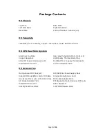
Page 3: ...pper Baseplate High Quality Thermal Paste 3 5g 6mm OD Copper Heat pipes x8 Dumbbell Tool to apply thermal paste Installation Screw Kit Intel CPU Bottom Plate H5 Accessories Multipurpose HDD Rack x2 ATX SFX Flex Power Supply Rack Side I O PCB w 4PIN 5 5 2 5 DC Cable Internal AC Extension Cord Hex Screw Driver x2 2 5 4 0mm Tip DC Socket Adapter Plate AC Socket Adapter Plate PCI Bracket Standard x3 L...

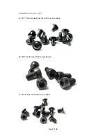
Page 4: ...Page 4 of 34 Installation Screw List A M3 5 Round Head Screw with Cushion Black B M5 8 CUP Head HEX Screw Black C M4 8 Flat Head HEX Screw Black ...

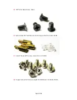
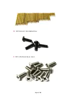
Page 5: ...5 of 34 D M3 5 Flat Head Screw Black E Nylon Screw M3 6 White and 10mm Copper Post for Side I O PCB F 16 32 Thread M3 6 screw Silver For 3 5 HDD G Copper Screw Post Various Length for HDD Rack 10 30 40 50mm ...

Page 6: ...Page 6 of 34 H M2 6 Screw for Slim Optical Drive I M4 12 Flat Head Screw Silver ...

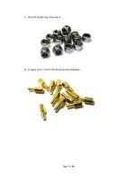
Page 7: ...Page 7 of 34 J M3 Self Tightening Nut Silver K Copper Post 7mm for Motherboard Installation ...

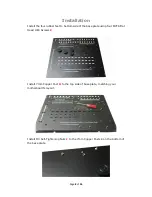
Page 8: ... to bottom side of the base plate using four M4 8 Flat Head HEX Screws C Install 7mm Copper Post K to the top side of base plate matching your motherboard s layout Install M3 Self Tightening Nuts J to the 7mm Copper Posts K on the bottom of the base plate ...

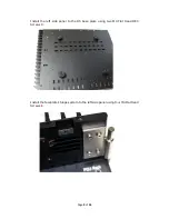
Page 9: ...Page 9 of 34 Install the left side panel to the H5 base plate using two M4 Flat Head HEX Screws C Install the faceplate s hinge system to the left side panel using four M4 Flat Head Screws I ...

Page 10: ...er x8 H 2 M3 10 CUP Head HEX Screw Silver x8 H 3 M 3 30 Round Head Screw Silver x4 H 4 M3 14 Flat Head Screw Black x16 H 5 Intel and AMD CPU Bottom Rack x4 H 6 Intel CPU LGA115x Bottom Rack x1 H 7 Bottom Holder and Double Tape x4 H 8 Plastic Screw Holder Black x4 H 9 Aluminum Plate for Heat pipe Installation x4 ...

Page 11: ... Rack H 5 to the bottom side of the copper base plate using four M3 3 Flat Head screws H 1 Install the Plastic Screw Holders H 8 to the ends of the two racks H 5 Please Ensure the Plastic Screw Holders H 8 are oriented correctly Next install four M3 30 Round Head Screws H 3 into the Plastic Screw Holder H 8 ...

Page 12: ...ing Do not over apply thermal paste as it will greatly decrease heat transfer efficiency For Intel systems place the CPU Bottom Rack H 6 on the backside of the motherboard s Intel CPU socket LGA1151 1155 1150 and for AMD systems use four pieces of white double sided tape to secure the four bottom holders H 7 to the backside of the socket Mount the motherboard to the H5 base plate using M3 5 Flat H...

Page 13: ... you stop tightening the screws when the M3 threads have just fully emerged within the bottom holder H 6 or H 7 Do NOT over tighten the H 3 screws and avoid putting too much pressure on the CPU Apply a very thin layer of thermal paste to the heat pipe grooves on left panel and the copper plate grooves using the dumbbell shaped tool provided Warning Do not over apply thermal paste as it will decrea...

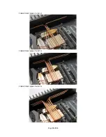
Page 14: ...Page 14 of 34 Install Heat pipes 1 and 2 Install Heat pipes 3 and 4 Install Heat pipes 5 and 6 ...

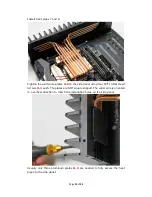
Page 15: ...de panel using four M3 14 Flat Head Screws H 4 each The plates are NOT square shaped The wider side is oriented in a vertical direction to match the installation holes on the side panel Usually only three aluminum plates H 9 are needed to fully secure the heat pipes to the side panel ...

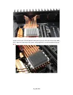
Page 16: ...Page 16 of 34 Apply a thin layer of thermal paste along each groove of the aluminum top plate then install the aluminum top plate using eight M3 10 CUP Head HEX Screws H 2 ...

Page 17: ...ng an ITX motherboard Install both the 160W AC DC and 160W DC ATX on the left side for ATX microATX ITX motherboard Install ATX SFX Flex PSU using the universal rack on the left side Attach the universal rack to the power supply using two M3 5 Round Head Screws A We recommend this to be the last step in a full H5 build You can install the AC extension cord and fully secure the ATX SFX Flex PSU to ...

Page 18: ...read 6mm Screws F and 2 5 HDD using M3 5 Flat Head Screws D to the hard drive rack There are three HDD rack installation positions on H5 base plate anyone or all of which may be used based on the build layout Please choose the arrangement most suitable for your individual project ...

Page 19: ...opper posts G This arrangement may be implemented on any of the three HDD mounting points if the spot is unobstructed If you plan to install 5 25 device such as 5 25 optical drive or hot swap HDD cage on to the right side there are two options A If a 250W HiFi DC ATX has been installed on the right side install four 40mm copper posts G to the H5 base plate surrounding the DC ATX Secure the 5 25 de...

Page 20: ...n the HDD rack Place the 5 25 device on top of the 10mm copper post and secure with 4pcs M3 5 A screws If no 5 25 Device is installed HDD racks may be double stacked on the right side The third HDD mounting position can only be utilized if using an ITX motherboard and not installing a horizontally oriented PCI card After all hard drive and optical driver are installed the HDD racks can be secured ...

Page 21: ...Page 21 of 34 Install slim ODD by using four M2 6 Screws H to secure drive to the H5 slim ODD rack Attach slim ODD with rack to the copper posts using two M3 5 Round Head Screws with Cushions A ...

Page 22: ...he card on the motherboard BEFORE installing the H5 back plate Install the power adapter plate onto the H5 back plate before attaching the back plate to the H5 chassis If you are using an AC C14 IEC connector install the AC adapter plate using four M3 5 Round Head Screws with Cushions A and the AC C14 connector using two M3 5 Flat Head Screws D ...

Page 23: ... is included with the 300W ATX linear PSU or available for purchase separately Install four 4mm copper post included with the ATX Modular board onto the H5 back plate then install the ATX modular bridge board to the posts using four M3 5 Round Head Screws with Cushions A Verify orientation of the ATX Modular bridge board as it will cause conflict with the side panel if incorrectly installed ...

Page 24: ...screws E Install the left side panel to the H5 base plate using two M4 8 Flat Head HEX Screws C Attached the motherboard I O shield plate to the H5 back plate and install the back plate to the chassis using four M5 8 CUP Head HEX Screw B Lock the half height card using one M3 5 Round Head Screw with Cushion A to the 3 4 M3 thread hole ...

Page 25: ... riser card from the motherboard to the video card and turn on the PC If the PCIEx16 card is functioning properly and showing the correct PCIE version 3 0 and speed x16 turn off the PC and disconnect the GPU HDPLEX GPU Heat Sink system parts list 6mm OD Copper Heat pipes x8 Aluminum Top Cover Copper Base Plate High Quality Thermal Paste 3 5g Aluminum Plate for Heat pipe installation x4 V 1 M3 14 M...

Page 26: ...y install the copper plate using four M3 7 screws with springs V 3 A very thin layer of thermal paste may be applied between the copper base plate and GPU Secure the GPU mounting bracket to the H5 back plate using one M3 5 Round Head Screw with Cushion A Install the silicon PCIEx16 Riser card Ensure proper orientation ...

Page 27: ...Page 27 of 34 Install the video card to the H5 back plate Slide the two bracket tip inside and using 1pcs A firmly attach the video card bracket to H5 back plate ...

Page 28: ... the side panel grooves and then install the eight heat pipes following the below pattern Install the three aluminum plates to the side panel using four M3 14 M3 screws V 1 each Next install the aluminum top cover using eight M4 10 CUP Head M3 screws V 2 ...

Page 29: ...tive thermal pad is included in the H5 package which should be applied to the MOSFET and inductors on the GPU board Install heat sink blocks Not included on the thermal pad to increase heat dissipation from the MOSFET and inductors ...

Page 30: ...e PCB s jumpers can be adjusted If the luminance jumper is set to 0 the LED will emit full light and gradually reduce to zero light 30 seconds after being activated by touching the aluminum power button Install the PCB to the 5mm copper posts on the faceplate using four M3 5 Round Head Screws with Cushions A ...

Page 31: ...stall the power button onto the front of the H5 faceplate Attach the two copper hats to the M2 screw post from the back Turn on the PC to test the touch function Achieve the optimal touch sensitivity by adjusting the tightness of the two copper hats Install the copper lock system receiver half on the faceplate with the round head black M3 5 screw from the plastic bag which contains spring and copp...

Page 32: ...roper orientation Install the hinge top piece on to the H5 side panel using 2pcs I ensuring proper orientation Test the faceplate hinge mechanism to ensure proper functioning If the faceplate touches the floor while open in full please tighten the hinge top piece The faceplate may also be permanently locked by using two M5 8 CUP Head HEX Screws B ...

Page 33: ...HEX Screws C This is HDPLEX H5 Installation Manual Version 1 1 Please visit http www hd plex com hdplex h5 fanless computer case html for latest H5 installation guide This case is designed by Larry at HDPLEX If you have any suggestions for improvements or product feature request please don t hesitate to write to larry hd plex com Thanks for your purchase and support ...

Page 34: ... Fanless Chassis please visit our community at http www hd plex com forum Copyright 2015 HDPLEX Inc All rights reserved All trademarks are the property of their respective owners Reproduction in whole or in part without written permission is prohibited ...

Reviews: