background image

A u t o t o o l   2 0 0 0

TOC-Cover

Automation Instructions
Automatisierungsanleitung

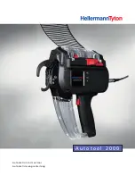
Summary of Contents for Autotool 2000 CPK

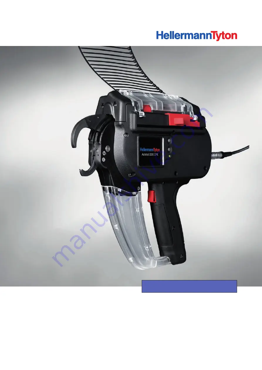
Page 1: ...A u t o t o o l 2 0 0 0 TOC Cover Automation Instructions Automatisierungsanleitung...

Page 2: ...2 US English DE Deutsch Automation Instructions 3 Automatisierungsanleitung 37...

Page 3: ...le ties and cable tie reels 10 5 Installation 11 5 1 Installing the bench mount kit CPK 11 5 1 1 Assembling the bench mount kit CPK 11 5 1 2 Securing the base plate 12 5 1 3 Inserting the tool 12 5 1...

Page 4: ...2 1 Description 29 8 2 2 Settings of the serial interface 29 8 2 3 Data format 29 8 2 4 Overview of commands sent via serial interface without data 30 8 2 5 Overview of commands sent via serial inter...

Page 5: ...y legible If the products are acquired by or sold on to a third party the following documents must be handed over to the new owner These instructions Documents relating to repair work Logs of repair w...

Page 6: ...f HellermannTyton Use of spare parts and accessories not tested and approved beforehand by HellermannTyton 2 4 Personnel qualification Under age persons and trainees are permitted to use the device on...

Page 7: ...is in full working order Use only accessories approved by HellermannTyton Accessories can affect the way in which the tool or product works 3 Functional description 3 1 AT2000 CPK 3 1 2 4 1 AT2000 CP...

Page 8: ...dle past the tool and use the foot operated switch to trigger tying Installing the bench mount kit CPK on page 11 Foot operated switch 2 can be used together with the bench mount kit CPK for easier ty...

Page 9: ...ing to be installed 4 2 Accessories and spare parts Depending on the purchase order the following components can be part of the scope of supply Name Article number AT2000 CPK 106 00000 Power pack with...

Page 10: ...els NOTE Cable ties and cable tie reels are not resistant against ageing The plastic deteriorates if storage time is prolonged f f Use up cable ties promptly Storage temperature 20 C 23 C Relative hum...

Page 11: ...sembly A of the bench mount kit CPK f f Slip the mount of the cable tie reel with clamping ring 6 through the hole in upright 5 f f Engage acorn nut 1 at the other side and secure the mount to upright...

Page 12: ...f f Slacken screw 3 and remove nut 4 f f Ease the handle fully apart f f Work the waste box down to remove f f Close the two parts of the handle f f Install the screws 9 8 6 7 f f Slacken screw 6 and...

Page 13: ...the cable tie reel NOTE To avoid signal disruptions position the power pack with control box no more than 5 m away from the tool 5 1 6 Installing the waste disposal equipment The cut offs drop through...

Page 14: ...f Secure rail runner 1 with screws 7 to upright 2 f f Slip reel mount with clamping ring 3 through upright 2 Be sure to check that direction of rotation of the pinion The pinion must be able to engage...

Page 15: ...f f Always keep the power pack CPK switched OFF while installation is in progress 1 2 3 4 f f Turn adapter 2 on hanger 1 until groove 3 in the collar clears pin 4 f f Pull out pin 4 and remove adapter...

Page 16: ...sion of the tool with clips 1 f f Make sure that there is nothing to obstruct accessibility to the tool the power pack with control box and the cable tie reel NOTE The connecting cable between tool an...

Page 17: ...x 8 down to open f f Slacken screw 6 f f Ease handle 7 to the rear and work it down to remove 5 3 2 Inserting the robot adapter CPK 6 9 f f Insert robot adapter CPK 9 into the groove in the tool and s...

Page 18: ...ositioning 5 5 1 Positioning the material for bundling f f Make sure that the material for bundle is always in the same position f f Bundle the material neatly Make sure there are no projecting cable...

Page 19: ...in safe working order see the maintenance schedule in the Operating Instructions for the tool CAUTION Crush hazard when jaws close f f Do not insert finders between top and bottom jaws f f Do not kee...

Page 20: ...g ring 2 f f Pass strip of cable ties 3 around relay roller 4 to the tool f f Make sure that the strip of cable ties is not twisted 6 5 Replacing the cable tie reel on the overhead suspension CPK 1 2...

Page 21: ...ted all sizes are rounded off and stated in millimeters mm HellermannTyton offers special CAD models for planning integration into automatic systems 7 1 AT2000 CPK 243 282 314 25 32 85 77 103 5 34 30...

Page 22: ...E Automation Instructions CPK 10 2015 106 29009 Technical data 22 7 2 Power pack with control box 110 257 5 93 3 3 Line voltage 100 V 230 V Line frequency 50 60 Hz Protection class I Weight approx 1 1...

Page 23: ...ready Red Fault Yellow Binding cycle active Blue Navigation in main menu binding not possible 9 LED indicator Data Green PC connected AT2000 CPK connected USB stick found USB stick can be removed Red...

Page 24: ...ed 3 Zero voltage 0 V 4 Voltage 25 2 V 5 Data B Signal RS 485 A The red dot above the socket for the tool makes the plug easier to position properly 7 2 3 Pinout of serial interface power pack with co...

Page 25: ...utomation Instructions CPK 10 2015 106 29009 Technical data 25 7 3 Bench mount kit CPK 300 35 300 804 177 5 592 409 Weight 9540 g Weight with cable tie reel 11300 g Weight with cable tie reel and tool...

Page 26: ...nstructions CPK 10 2015 106 29009 Technical data 26 7 3 1 BMK tool mount CPK 124 5 158 5 9 3 63 65 149 5 40 22 6 7 3 2 Hole pattern of BMK base plate CPK 260 20 5 3 20 260 20 20 7 3 3 BMK holder 785 5...

Page 27: ...Automation Instructions CPK 10 2015 106 29009 Technical data 27 7 4 Overhead suspension CPK 392 270 463 512 242 Weight 3 88 kg Weight with cable tie reel 5 64 kg Weight with cable tie reel and tool 7...

Page 28: ...pter CPK 12 15 15 42 35 3 18 2 56 2 9 6 20 18 8 36 8 52 2 8 8 26 2 38 2 Weight 0 11 kg Weight with tool 1 81 kg 7 6 Cable tie reel 135 390 18 Number of cable ties per reel 3500 Weight of reel full 1 7...

Page 29: ...A transfer always starts with 0x02 STX and always ends with 0x03 ETX The data between STX and ETX are always transmitted as ASCII characters 0 0x30 1 0x31 etc A 0x41 B 0x42 etc Only uppercase letters...

Page 30: ...eading Counter reading at last service Date of last service Setting for interruption head Setting for standby time Force and quality ABBD Trigger binding 8 2 5 Overview of commands sent via serial int...

Page 31: ...X 8 place counter Y 2 place temperature Z 2 place humidity time of binding A Error code B 20 place error data 8 3 Data logging Code Description Data 0001 Overload 0002 Speed error tensioning motor 00...

Page 32: ...gether by two strips of plastic one at the tip and one at the head Control box Printed circuit board in the power pack with sensor connection relay connections and serial interface Cycle motor Drive f...

Page 33: ...nt kit CPK UNS No Drawing Designation 106 40004 BMK arm CPK 106 40003 BMK upright CPK 123 90029 Relay roller CPK 120 84040 BMK reel mount OHS 120 84340 BMK clamping ring OHS 120 90983 Screw for tool m...

Page 34: ...BC EC35 39 1 5 4 0 PA66HIRHS Black BK 102 68355 ATS BC EC36 39 1 5 4 0 PA66HIRHS Black BK 102 68365 ATS BC EC37 39 1 5 4 0 PA66HIRHS Black BK 102 68375 ATS BC EC38 39 1 5 4 0 PA66 Black BK 102 68385 A...

Page 35: ...tter than 100 mm min UL94 V2 Weathering Good weather resistance under normal climate conditions The effects caused by exposure to ultraviolet light are considerably reduced by the addition of carbon T...

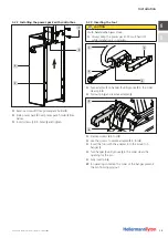
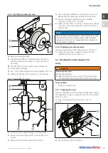
Page 36: ...US DE Automation Instructions CPK 10 2015 106 29009 Appendix 36 9 5 Cable tie strip...

Page 37: ...ug und Netzger t mit Steuerbox 44 4 5 2 Kabelbinder und Kabelbinderspulen 44 5 Montage 45 5 1 Montagevorrichtung CPK montieren 45 5 1 1 Montagevorrichtung CPK zusammensetzen 45 5 1 2 Grundplatte befes...

Page 38: ...nittstelle 63 8 2 1 Beschreibung 63 8 2 2 Einstellungen der seriellen Schnittstelle 63 8 2 3 Datenformat 63 8 2 4 Befehls bersicht serielle Schnittstelle ohne Daten 64 8 2 5 Befehls bersicht serielle...

Page 39: ...itung nicht mehr gut lesbar ist muss der Betreiber beim Hersteller Ersatz beschaffen Bei bergabe oder Weiterverkauf der Produkte an Dritte m ssen folgende Dokumente an den neuen Besitzer weiter gegebe...

Page 40: ...odifikationen an der Vorrichtung und deren Bestandteilen ohne Zustim mung von HellermannTyton Einsatz von Ersatzteilen und Zubeh r welche nicht von HellermannTyton gepr ft und freigegeben wurden 2 4 Q...

Page 41: ...ion anschlie end berpr fen Ausschlie lich Zubeh r verwenden das von HellermannTyton freigegeben ist Der Einsatz von Zubeh r kann die Arbeit mit dem Werkzeug oder Produkt ver ndern 3 Funktionsbeschreib...

Page 42: ...der Benutzer das B ndelgut am Werkzeug vorbeif hren und den Abbinde vorgang mit dem Fu schalter ausl sen Montagevorrich tung CPK montieren auf Seite 45 Der Fu schalter 2 kann zusammen mit der Montage...

Page 43: ...ckte Komponenten k nnen beim Transport besch digt werden f f Alle Komponenten erst vor der Montage auspacken 4 2 Zubeh r und Ersatzteile Abh ngig von der Bestellung k nnen folgende Bauteile Bestandtei...

Page 44: ...und Kabelbinderspulen HINWEIS Kabelbinder und Kabelbinderspulen sind nicht alterungs best ndig Lange Lagerzeiten beeintr chtigen die Lebens dauer des Kunststoffs f f Kabelbinder z gig verarbeiten Lage...

Page 45: ...ung CPK m glich f f Die Aufnahme der Kabelbinderspule mit Klemmring 6 durch die Bohrung der S ule 5 stecken f f Die Hutmutter 1 auf der Gegenseite aufsetzen und die Aufnahme an der S ule 5 befestigen...

Page 46: ...hraube 3 l sen und die Mutter 4 abnehmen f f Das Griffsystem vorsichtig aufspreizen f f Die Abfallbox nach unten abnehmen f f Das Griffsystem zusammendr cken f f Die Schrauben einschrauben 9 8 6 7 f f...

Page 47: ...le achten HINWEIS Das Netzger t mit Steuerbox nicht mehr als 5 m vom Werkzeug entfernt positionieren um Signalst rungen zu vermeiden 5 1 6 Abfallentsorgung anbringen Der Kabelbinderabfall f llt durch...

Page 48: ...mit den Schrauben 7 an der S ule 2 befestigen f f Die Spulenaufnahme mit Klemmring 3 durch die S ule 2 stecken Dabei die Drehrichtung des Ritzels beachten Das Ritzel muss einrasten k nnen f f Auf der...

Page 49: ...Zangen f f Montagearbeiten nur bei ausgeschaltetem Netzger t durchf hren 1 2 3 4 f f Den Adapter 2 am B gel 1 drehen bis die Nut 3 am Bund den Stift 4 freigibt f f Den Stift 4 herausziehen und Adapte...

Page 50: ...gs mit Clips 1 befestigen f f Auf gute Zug nglichkeit des Werkzeugs des Netzger ts mit Steuerbox und der Kabelbinderspule achten HINWEIS Das Verbindungskabel zwischen Werkzeug und Netzger t mit Steuer...

Page 51: ...nten klappen f f Die Schraube 6 l sen f f Das Griffsystem 7 nach hinten schieben und nach unten abnehmen 5 3 2 Roboter Adapter CPK einsetzen 6 9 f f Den Roboter Adapter CPK 9 in die Nut am Werkzeug ei...

Page 52: ...Positionierung 5 5 1 B ndelgut positionieren f f Das B ndelgut immer gleich positionieren f f Das B ndelgut sauber vorb ndeln Abstehende Kabel enden vermeiden f f Darauf achten dass die Ober und Unte...

Page 53: ...ew hrleisten muss es einer regelm igen Wartung unterzogen werden siehe Wartungsplan der Betriebsanleitung des Werkzeugs VORSICHT Quetschgefahr durch schlie ende Zangen f f Finger nicht zwischen Ober u...

Page 54: ...2 aufsetzen f f Die Bandkette 3 um die Umlenkrolle 4 zum Werkzeug f hren f f Darauf achten dass keine Verdrehung der Bandkette auftritt 6 5 Kabelbinderspule an der H ngevorrichtung CPK austauschen 1...

Page 55: ...werden alle Ma e aufgerundet in mm angegeben F r die Planung bei der Integration in automatische Anlagen bietet HellermannTyton spezielle CAD Modelle an 7 1 Werkzeug AT2000 CPK 243 282 314 25 32 85 7...

Page 56: ...US DE Automatisierungsanleitung CPK 10 2015 106 29009 Technische Daten 56 7 2 Netzger t mit Steuerbox 110 257 5 93 3 3 Netzspannung 100 V 230 V Netzfrequenz 50 60 Hz Schutzklasse I Gewicht ca 1 18 kg...

Page 57: ...riebsbereit Rot Fehler Gelb Abbindezyklus aktiv Blau Navigation im Hauptmen keine Abbindung m glich 9 LED Signalleuchte Data Gr n PC angeschlossen Werkzeug AT2000 CPK angeschlossen USB Stick erkannt U...

Page 58: ...legt 3 Nullspannung 0 V 4 Spannung 25 2 V 5 Data B Signal RS 485 A Der rote Punkt oberhalb des Anschlusses f r das Werkzeug erleichtert die korrekte Positionierung des Steckers 7 2 3 Pinbelegung serie...

Page 59: ...ierungsanleitung CPK 10 2015 106 29009 Technische Daten 59 7 3 Montagevorrichtung CPK 300 35 300 804 177 5 592 409 Gewicht 9540 g Gewicht mit Kabelbinderspule 11300 g Gewicht mit Kabelbinderspule und...

Page 60: ...sanleitung CPK 10 2015 106 29009 Technische Daten 60 7 3 1 Werkzeugaufnahme BMK CPK 124 5 158 5 9 3 63 65 149 5 40 22 6 7 3 2 Bohrbild Bodenplatte BMK CPK 260 20 5 3 20 260 20 20 7 3 3 Halterung BMK 7...

Page 61: ...atisierungsanleitung CPK 10 2015 106 29009 Technische Daten 61 7 4 H ngevorrichtung CPK 392 270 463 512 242 Gewicht 3 88 kg Gewicht mit Kabelbinderspule 5 64 kg Gewicht mit Kabelbinderspule und Werkze...

Page 62: ...Roboter Adapter CPK 12 15 15 42 35 3 18 2 56 2 9 6 20 18 8 36 8 52 2 8 8 26 2 38 2 Gewicht 0 11 kg Gewicht mit Werkzeug 1 81 kg 7 6 Kabelbinderspule 135 390 18 Anzahl Kabelbinder Spule 3 500 Gewicht...

Page 63: ...t Ein Transfer beginnt immer mit 0x02 STX und endet immer mit 0x03 ETX Die Daten zwischen STX und ETX werden als ASCII Zeichen bertragen 0 0x30 1 0x31 usw A 0x41 B 0x42 usw F r Befehle werden nur Gro...

Page 64: ...g Datum der letzten Wartung Einstellung f r Unterbrechung Kopf Einstellung f r Standby Zeit Kraft und Qualit t ABBD Abbindung ausl sen 8 2 5 Befehls bersicht serielle Schnittstelle mit Daten Die Steue...

Page 65: ...8 stelliger Z hler Y 2 stellige Temperatur Z 2 stellige Feuchte Zeit der Abbindung A Fehlercode B 20 Stellen Fehlerdaten 8 3 Datenprotokollierung Code Beschreibung Data 0001 berlast 0002 Drehzahlfehl...

Page 66: ...em Kunststoffband zusammengehalten werden BMK Bench Mount Kit Montagevorrichtung OHS Overhead Suspension H ngevorrichtung Spannmotor Antrieb zum Straffen des Kabelbinders Steuerbox Platine im Netzger...

Page 67: ...CPK UNS Nr Zeichnung Bezeichnung 106 40004 Arm BMK CPK 106 40003 S ule BMK CPK 123 90029 Umlenkrolle CPK 120 84040 Spulenaufnahme BMK OHS 120 84340 Klemmring BMK OHS 120 90983 Schraube Werkzeugaufnah...

Page 68: ...1 5 4 0 PA66HIRHS Schwarz BK 102 68355 ATS BC EC36 39 1 5 4 0 PA66HIRHS Schwarz BK 102 68365 ATS BC EC37 39 1 5 4 0 PA66HIRHS Schwarz BK 102 68375 ATS BC EC38 39 1 5 4 0 PA66 Schwarz BK 102 68385 ATS...

Page 69: ...en klimatischen Bedin gungen gut witterungsbest ndig Die Auswirkungen verursacht durch UV Bestrahlung werden durch Bei gabe von Kohlenstoff wesentlich ver z gert Durch Beigabe eines Stabili sators wir...

Page 70: ...US DE Automatisierungsanleitung CPK 10 2015 106 29009 Anhang 70 9 5 Bandkette...

Page 71: ......

Page 72: ...nternational Medical and Technology Park Plymouth Devon PL6 5WR Tel 44 1752 701 261 Fax 44 1752 790 058 E Mail info HellermannTyton co uk www HellermannTyton co uk HellermannTyton Ltd UK Sharston Gree...

Reviews: