background image

Summary of Contents for Pandar40

Page 1: ......

Page 2: ...not be tampered with and must not be changed in any way There are no user serviceable parts inside the device For repairs and maintenance inquiries please contact an authorized Hesai Technology service provider Laser Safety Notice Laser Class 1 This device satisfies the requirements of IEC 60825 1 2014 21 CFR 1040 10 and 1040 11 except for deviations pursuant to Laser Notice No 50 dated June 24 20...

Page 3: ...vice can withstand a sudden impact of 50 G for 11 milliseconds or 3 21 Grms short term vibration within 5 Hz to 2000 Hz for 4 hours Radio Frequency Interference Please observe the signs and notices on the device that prohibit or restrict the use of electronic devices Although the device is designed tested and manufactured to comply with the regulations on RF radiation the radiation from the device...

Page 4: ...l 9 2 4 Get Ready to Use 12 3 Data Structure 13 3 1 Point Cloud Data Packet 14 3 2 GPS Data Packet 17 4 Web Control 22 4 1 Home 22 4 2 Settings 23 4 3 Device Info 24 4 4 Upgrade 25 5 PandarView 26 5 1 Installation 26 5 2 Use 27 5 3 Features 29 6 Sensor Maintenance 33 7 Troubleshooting 34 Appendix I Channel Distribution 36 Appendix II Calculation of Laser Firing Time 38 Appendix III Support and Con...

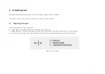
Page 5: ...1 Operating Principle Distance Measurement Time of Flight ToF 1 A laser diode emits a beam of ultrashort laser pulses onto the object 2 Diffuse reflection of the laser occurs upon contact with the target object The beams are detected by the optical sensor 3 Distance to object can be accurately measured by calculating the time between emission and receipt by the sensor Figure 1 1 ToF Formula ...

Page 6: ...Top View The LiDAR s coordinate system is shown above The Z axis is the axis of rotation The origin is shown as a red dot in Figure 1 6 on the next page After geometric transforms all the measurements are relative to the origin Each laser channel has an intrinsic horizontal angle offset When Channel 12 passes the zero degree position y axis illustrated in Figure 1 4 the azimuth data in the corresp...

Page 7: ...ion The vertical resolution is 0 33 between Channel 6 and Channel 30 1 between Channel 1 and Channel 6 Channel 30 and Channel 40 detailed in Appendix I Figure 1 5 Channel Vertical Distribution Figure 1 6 Laser Firing Position ...

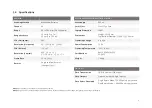
Page 8: ... m 2 cm 1 to 200 m Dimensions Height 101 50 mm Top Bottom Diameter 116 00 112 00 mm FOV Horizontal 360 Operating Voltage 9 to 32 V Resolution Horizontal 0 2 10 Hz 0 4 20 Hz Power Consumption 15 W FOV Vertical 16 to 7 Operating Temperature 20 to 60 Resolution Vertical 0 33 6 to 2 1 16 to 6 2 to 7 Certifications RoHS REACH WEEE CE EMC Frame Rate 10 Hz 20 Hz Weight 1 46 kg Returns Single and Dual Ret...

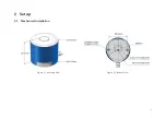
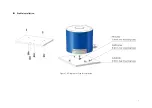
Page 9: ...5 2 Setup 2 1 Mechanical Installation Figure 2 1 Isometric View Figure 2 2 Bottom View ...

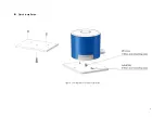
Page 10: ...6 Quick Installation Figure 2 3 Diagram of Quick Installation ...

Page 11: ...7 Stable Installation Figure 2 4 Diagram of Stable Installation ...

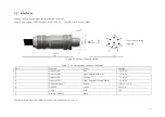
Page 12: ...able 2 1 Pin Description of Phoenix Connector Pin Function Color Voltage 1 Ethernet RX Blue 1 V to 1 V 2 Ethernet RX Light Blue Blue White 1 V to 1 V 3 Ethernet TX Orange 1 V to 1 V 4 Ethernet TX Light Orange Orange White 1 V to 1 V 5 GPS Serial Data White 13 V to 13 V 6 GPS PPS Yellow 3 3 V 5 V 7 12 V Red 12 V 8 Ground Return Black The cable length from the LiDAR exit to the tip of the connector ...

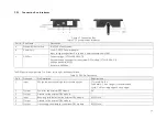
Page 13: ...ion box The connection box comes equipped with a power port a GPS port and a standard Ethernet port The cable length between the connector and the connection box is 1 7 m by default Phoenix part number SACC M12FS 8CON PG 9 SH 1511860 female on the connection box Figure 2 6 Connection Box ...

Page 14: ...232 Baud rate 9600 bps The GPS port pin numbers are 1 to 6 from left to right defined as follows Table 2 3 GPS Pin Description Pin Direction Pin Description Requirements 1 Input PPS pulse per second signal for synchronization TTL level 3 3 V 5 V Pulse width 1 ms or longer is recommended Cycle 1 s from rising edge to rising edge 2 Output Power for the external GPS module 5 V 3 Output Ground for the...

Page 15: ...11 2 3 2 Connection Figure 2 7 LiDAR Connection When Using the Connecting Box ...

Page 16: ...0 replace enp0s20f0u2 with the local network port name 1 Open the Network Sharing Center click on Ethernet 2 In the Ethernet Status interface click on Properties 3 Double click on Internet Protocol Version 4 TCP IPv4 4 Configure the IP address to 192 168 1 100 and subnet mask to 255 255 255 0 To record and display point cloud data see Chapter 5 PandarView To set parameters check device info and up...

Page 17: ...ructure 100 Mbps Ethernet UDP IP is used for data output The output data includes Point Cloud Data Packets and GPS Data Packets Each data packet consists of an Ethernet header and UDP data Figure 3 1 Data Structure ...

Page 18: ...tion broadcast 0xFF 0xFF 0xFF 0xFF 0xFF 0xFF Source xx xx xx xx xx xx Ethernet Data Packet Type 2 bytes 0x08 0x00 Internet Protocol 20 bytes Shown in the figure below UDP Port Number 4 bytes UDP source port 0x2710 representing 10000 Destination port 0x0940 representing 2368 UDP Length 2 bytes 0x04F0 representing 1264 bytes 8 bytes more than the size of the Point Cloud UDP Data shown in Figure 3 1 ...

Page 19: ... Current reference angle of the rotor Azimuth 15 0 lower byte Azimuth_L 7 0 upper byte Azimuth_H 15 8 Azimuth Angle Azimuth_H Azimuth_L 100 Azimuth 100 Channel XX 3 bytes 2 byte distance data Distance 15 0 lower byte Distance_L 7 0 upper byte Distance_H 15 8 Distance Value Distance_H Distance_L 4 mm Distance 4 Maximum Distance Value 2 16 1 4 mm 262 14 m 1 byte reflectivity data Reflectivity in per...

Page 20: ...eturn Mode Information 1 byte 0x37 for Strongest Return mode 0x38 for Last Return mode and 0x39 for Dual Return mode Factory Information 1 byte 0x42 or 0x43 Example of UDP Data Analysis in Point Cloud Data Packets Take Pandar40 s Channel 5 in Block 3 of the UDP Data as an example 1 Vertical angle of Channel 5 is 3 00 according to Appendix I Channel Distribution 2 Horizontal angle is the current re...

Page 21: ...ts the 4 byte GPS Timestamp field stores the start time of the first block in that packet The timestamp is counted from the beginning of the hour and is in units of μs as shown in Section 3 1 2 For example if the timestamp is 37 x 60 21 x 1000000 235682 then the start time of the first block is 37 minutes 21 seconds and 235682 μs The GPS module sends first the PPS signal and then the GPRMC message...

Page 22: ...xFF 0xFF 0xFF 0xFF Source xx xx xx xx xx xx Ethernet Data Packet Type 2 bytes 0x08 0x00 Internet Protocol 20 bytes Shown in the figure below UDP Port Number 4 bytes UDP source port 0x2710 represents 10000 Destination port 0x277E represents 10110 UDP Length 2 bytes 0x208 representing 520 bytes 8 bytes more than the size of the GPS UDP Data shown in Figure 3 1 UDP Checksum 2 bytes 0x0000 representin...

Page 23: ...byte first in ASCII μs Time 4 bytes In units of μs lower byte first GPRMC data 77 bytes ASCII code valid till 2 bytes after GPRMC sentence that contains UTC time information received from an external GPS module reserved 411 bytes 404 bytes of 0xDF location valid or not 1 byte ASCII code obtained from GPRMC A hex 41 for Valid Position V hex 56 for Invalid Position NUL hex 0 for GPS being unlocked f...

Page 24: ...L hex 0 for GPS being unlocked 09 UTC Date Date information Can be in ddmmyy day month year format The LiDAR s GPS data interface is compatible with a variety of GPRMC formats as long as 01 is the hour minute and second information 09 is the date information For example the following two formats are both acceptable GPRMC 072242 A 3027 3680 N 11423 6975 E 000 0 316 7 160617 004 1 W 67 GPRMC 065829 ...

Page 25: ...nth 0x32 0x31 2 1 12 Day 0x30 0x32 0 2 20 UTC Time Field Data ASCII Code Characters Meaning Second 0x32 0x35 2 5 52 Minute 0x35 0x34 5 4 45 Hour 0x32 0x31 2 1 12 μs Time 4 bytes in units of μs using the same clock source as the GPS Timestamp in Point Cloud Data Packets At the rising edge of each PPS signal the μs timestamp will be set to minute 60 second 1000000 μs ...

Page 26: ...2 Set the IP address according to Section 2 4 Get Ready to Use 3 Enter this URL into your web browser 192 168 1 201 index html NOTE Use Google Chrome or Firefox instead of IE Turn off VPN 4 1 Home Figure 4 1 Home Page of Web Control Spin Rate of the motor revs per minute frame rate Hz 60 GPS PPS Status Lock LiDAR s internal clock is in sync with the GPS Unlock Not in sync ...

Page 27: ...lt the LiDAR s zero degree position defined in Section 1 2 is not in sync with PPS If syncing is needed check the check box and input a sync angle Angle Range 0 360 Outside the specified angle range there will be no laser firing nor data generated If the start and end angles are the same all lasers will only fire at this particular angle Return Mode Last Strongest Dual Return Rotation Direction Cl...

Page 28: ...24 4 3 Device Info Shows the device model serial number MAC address and software hardware firmware versions Figure 4 8 Device Info Page of Web Control ...

Page 29: ... Upload button and select an upgrade file provided by Hesai Reboot the LiDAR when the upgrade is complete Below shows the software and firmware versions described in this manual Figure 4 9 Firmware Upgrade Page of Web Control ...

Page 30: ...indows PandarView_Windows_V1 6 9 msi python 2 7 13 msi When upgrading PandarView to a newer version please uninstall the current version Double click and install python Use the default settings in the setup wizard including install for all users Double click and install PandarView_Windows using the default settings Ubuntu 16 04 PandarView_Installer_V1 6 9 tar gz Enter the following command in the ...

Page 31: ...ile window Select a PCAP file to open Record a PCAP File Import a Correction File Click on to pop up the Choose Output File window Click on Save to begin recording a PCAP file Click on again to stop recording Figure 5 2 Choose Output File Each LiDAR comes with a correction file CSV in the provided USB disk When a PCAP file is open click on File in the menu bar and Import Correction File Figure 5 3...

Page 32: ...rward May click again to adjust the forward speed 2x 3x 1 2x 1 4x and 1x Jump to the end of the file Save a single frame to CSV the XYZ coordinates as the first three columns While playing this Record button will be gray and unclickable While playing click to loop playback Otherwise the player will stop at the end of the file Save multiple frames to PCAP Specify the start and end frames Save multi...

Page 33: ...rl key to make a measurement in units of meters Click on again to quit Mouse Shortcuts Distance Reference Circles Slide the scroll wheel up down to magnify minimize Drag while holding the left button to adjust the point of view Drag while holding the scroll wheel to pan NOTE The bottom left coordinate axes show the current point of view Click on to show hide the 12 distance reference circles in gr...

Page 34: ...rn and Dual Return Enter the UDP port number and click Set to apply it Channel Selection Click on to show hide point cloud data from the selected laser channels Check Uncheck the boxes on the left to show hide each channel Check the Enable Disable all option at the bottom of the table to show hide all channels ...

Page 35: ...iew the data of the highlighted points as shown below Some of the data fields are defined below Field Description points The XYZ coordinates of each point azimuth Rotor s current reference angle azimuth_calib Azimuth horizontal angle offset To cancel the selection click on again and click on any place outside the selected area ...

Page 36: ...color legend at the lower right corner The default color scheme is intensity based Users can choose from other colors schemes based on azimuth azimuth_calib distance elevation laser_id or timestamp Click on to open or close the Color Editor ...

Page 37: ...sure is stained with dirt fingerprints or oil perform the follow cleaning steps 1 Spray the LiDAR enclosure with warm neutral solvent using a spray bottle Solvent type 99 isopropyl alcohol IPA or 99 ethanol absolute alcohol Solvent temperature 40 to 60 2 After the stains on the LiDAR enclosure loosen gently wipe the enclosure along its curved surface with a piece of soft microfiber cloth 3 Should ...

Page 38: ...rade page of web control If the version is not shown properly but as xxxx contact Hesai for further diagnostics Can receive data on Wireshark but not on PandarView 1 Make sure the Destination IP and the Destination LiDAR Port are set correctly on the Settings page of web control 2 Make sure the PC s firewall is disabled Cannot open web control 1 Make sure the Ethernet cable is properly connected 2...

Page 39: ...ual importing 3 Check for packet loss If no packet is missing while the point cloud flashes please update PandarView to the latest version and restart the PC If problem persists try connecting the LiDAR to another PC GPS cannot be locked 1 Make sure the GPS receiver is properly connected 2 Make sure the PPS signal is connected to the LiDAR 3 Make sure the Destination GPS Port is correct on the Set...

Page 40: ...t Azimuth Vertical Angle Elevation Instrument Range in meters Range in meters with Reflectivity 01 Top Beam 0 00 7 00 110 200 20 02 0 00 6 00 110 200 20 03 0 00 5 00 110 200 20 04 0 00 4 00 110 200 20 05 2 50 3 00 110 200 20 06 2 50 2 00 210 200 20 07 2 50 1 67 210 200 20 08 5 00 1 33 210 200 20 09 2 50 1 00 210 200 20 10 2 50 0 67 210 200 20 11 5 00 0 33 210 200 20 12 Horizontal Beam 2 50 0 00 21...

Page 41: ...200 20 23 2 50 3 67 210 200 20 24 0 00 4 00 210 200 20 25 5 00 4 33 210 200 20 26 2 50 4 67 110 200 20 27 2 50 5 00 110 200 20 28 5 00 5 33 110 200 20 29 2 50 5 67 110 200 20 30 2 50 6 00 110 200 20 31 2 50 7 00 110 200 20 32 2 50 8 00 110 200 20 33 0 00 9 00 110 200 20 34 0 00 10 00 110 200 20 35 0 00 11 00 110 200 20 36 0 00 12 00 110 200 20 37 2 50 13 00 110 200 20 38 2 50 14 00 110 200 20 39 2...

Page 42: ...g time is t0 the start time of each block the time when the first laser starts firing can be calculated For Pandar40 there are 10 blocks of ranging data in each Point Cloud Data Packet as shown below Each block contains the ranging data from 40 channels one return per channel Table II 1 Point Could UDP Data Ranging Data Ranging Data 1240 bytes 10 blocks Block1 Block2 Block3 Block10 0xFFEE 0xFFEE 0...

Page 43: ...ed by one round of firing is stored in two adjacent blocks the odd number block is the last return and the even number block is the strongest return If the last and strongest returns coincide the second strongest return will be placed in the even number block Therefore Block 1 Block 2 have the same firing time Block 3 Block 4 the same firing time and so on Table II 3 Start Time of Each Block Dual ...

Page 44: ... 4 17 18 t6 0 93 6 1 6 10 8 37 t6 0 93 2 1 6 5 18 38 t6 0 93 6 1 6 11 9 33 t6 0 93 3 1 6 5 19 34 t6 0 93 7 1 6 11 10 1 t6 0 93 4 1 6 5 20 2 t6 0 93 8 1 6 11 Firing Sequence Laser ID Firing Time μs Firing Sequence Laser ID Firing Time μs 21 13 t6 0 93 9 1 6 11 31 16 t6 0 93 14 1 6 16 22 26 t6 0 93 9 1 6 12 32 29 t6 0 93 14 1 6 17 23 31 t6 0 93 10 1 6 12 33 32 t6 0 93 15 1 6 17 24 9 t6 0 93 11 1 6 1...

Page 45: ...ty or fitness for any particular purpose Further Hesai Technology reserves the right to revise this publication and to make changes from time to time in the contents hereof without obligation to notify any person of such revision or changes HESAI and HESAI logo are registered trademarks of Hesai Technology All other trademarks service marks and company names in this manual or on Hesai s official w...

Page 46: ......

Reviews: