background image

Mutant Bassdrum 


7.2.2014


Mutant Bassdrum assembly tips v1.05 

PG1 


hexinverter.net electronics, 2014 


eurorack analogue bassdrum DIY assembly tips v1.05 

hexinverter.net


This guide should help you on the quest to build yourself a hexinverter Mutant Bassdrum eurorack module 
from a PCB/faceplate set. 

It is not a full blown step-by-step guide like with hexinverter 

full kit

 products

 and 

assumes you have successfully built some easier projects before from full kits (such as Orbitals, Galilean 
Moons, etc.) 

FINDING PARTS 


As with all hexinverter DIY projects, 

you should NOT blindly trust the Mouser Project Cart provided

. It is 

meant to save you the pain of searching for every common part on Mouser, but

, that doesn’t mean you don’t 

still have to go through the BoM line by line and make sure you’ve sourced each part for your build!

 I promise 

you will 

not

 be happy if you blindly order the cart, expecting to receive 100% of the components you need for 

the build – you cannot acquire all the pieces you need from Mouser alone! So make sure to read the Google 
Docs hosted bill of materials for the project. I suggest printing it out and checking each item off line by line 
to make sure you’ve accounted for it in your parts orders. I list sources in the BoM when available and even 
provide handy comments to help you find parts easier. And if you can’t find something, pop by the 

Muffwiggler Music Tech DIY Forum

 thread for the project and someone (perhaps myself) will help you out 

there so others can benefit from the answer to your problem as well. 

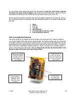
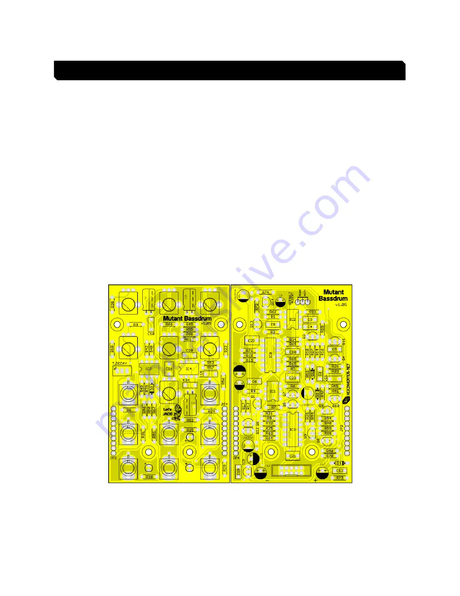
STEP 1: Board-level components 


Summary of Contents for mutant

Page 1: ...on Mouser but that doesn t mean you don t still have to go through the BoM line by line and make sure you ve sourced each part for your build I promise you will not be happy if you blindly order the cart expecting to receive 100 of the components you need for the build you cannot acquire all the pieces you need from Mouser alone So make sure to read the Google Docs hosted bill of materials for the...

Page 2: ...ertain you haven t made any mistakes I recommend putting the PCB stack together with the headers Don t solder anything until you re certain that the headers are all correct and your stack matches the way it is supposed to be assembled I like to put the boards together with the headers fitted but not soldered I then tack one leg of each header so I can adjust them until it all sits straight before ...

Page 3: ...against the panel so they raise off the PCB a bit 7 Solder one leg of each pot and then reheat pushing the pots flat against the PCB 8 Solder one leg of each jack and then reheat pushing the jack flat against the panel 9 Solder one leg of each part and reheat adjusting them to their final position on the panel 10 Once you are happy with the position of everything solder everything 11 Take a piece ...

Page 4: ...e PCB stack together Plug the top PCB into the control PCB for testing but don t install the screws and spacers yet You should be able to test everything with it just loosely assembled Once you re confident everything works properly assemble the PCB stack with the screws and spacers Then install the panel onto the PCB stack and tighten down all the control surface parts This is what the finished p...

Reviews: