

An ASSA ABLOY Group brand
2
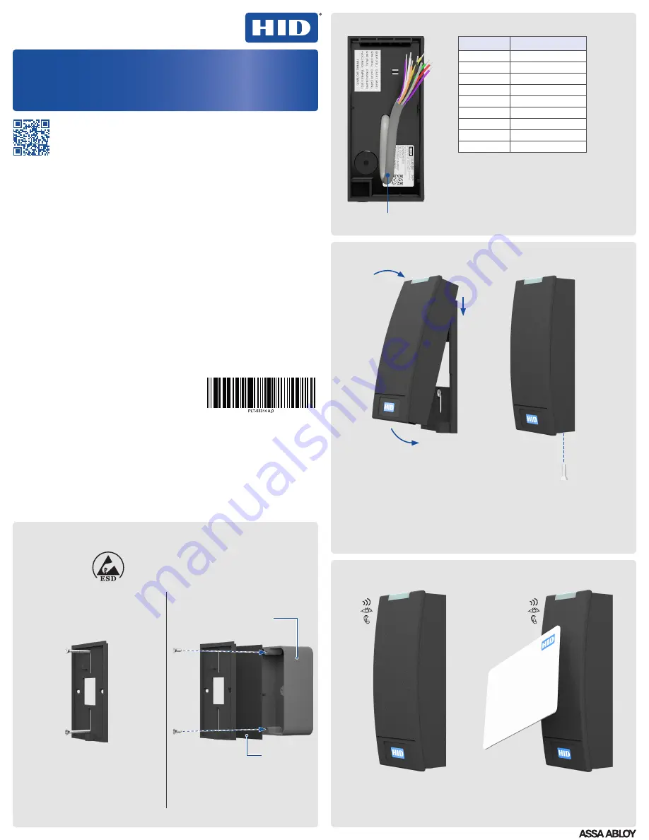
Wire the reader
3
Secure the reader to the backplate
4
Power and test the reader
Optional Features
Optical Tamper enabled by default
– Once activated, when the mounting plate is
removed, the optical tamper will open the circuit between Tamper#1 and Tamper#2
reader control lines. Tamper#1 and Tamper#2 control lines are interchangeable. Either of
these lines can be connected with the reader ground line to reduce the number of cable
cores required in the reader cable. The tamper control lines can operate within 0-12 VDC
and 0-100 mA.
Configuration
– The reader can be modified to meet the specific requirements of an
installation. Configuration options include; audio visual, and CSN outputs. See the HID
Reader Manager™ solution on www.hidglobal.com for further details.
PIGTAIL
DESCRIPTION
Yellow
Beeper Input
Orange
LED Input (GRN)
Black
Ground (RTN)
Red
+VDC
Drain
Unused
Violet
*Tamper #1
Violet/White
*Tamper #2
White
Wiegand Data 1
Green
Wiegand Data 0
* Tamper Output. When activated or when the
reader is unpowered, the circuit between
Tamper#1 and Tamper#2 reader control lines
will open.
Note:
Wiring the reader incorrectly may
permanently damage the reader.
www.hidglobal.com/PLT-03681
Scan the QR code or visit the link to
see the multi-language electronic
version of this document.
Lisez le code QR ou suivez le lien
pour consulter la version française de
ce document.
Escanee el código QR o visite el
vínculo para consultar la versión en
Español de este documento.
Scannen Sie den QR-Code oder
öffnen Sie den Link für die deutsche
Version dieses Dokuments.
Faça a leitura do código QR ou acesse
o link da versão em português deste
documento.
Scansiona il codice QR o visita il
link della versione Italiana di questo
documento.
Отсканируйте QR-код или пройдите по
ссылке, чтобы получить версию этого
документа на русском языке.
扫描 QR 码或访问此 文档的中文版本的
链接。
この文書の日本語版を表示するには、QR
コードをスキャンするか、リンクを クリ
ックします。
QR 코드를 스캔하거나 링크를 방문하면 이
문서의 한국어 버전을 볼 수 있습니다.
Turn on the power.
The reader should beep and the
light bar should flash.
1
3
2
4
9"
(0.23m)
© 2018 HID Global Corporation/ASSA ABLOY AB. All rights reserved.
HID, the HID Brick logo, the Chain Design, HID Reader Manager,
HID Mobile Access, and iCLASS SE are trademarks or registered
trademarks of HID Global, ASSA ABLOY AB, or its affiliate(s) in the
US and other countries and may not be used without permission. All
other trademarks, service marks, and product or service names are
trademarks or registered trademarks of their respective owners.
Supplied parts
iCLASS SE R10 Reader (1)
Installation Guide (1)
0.138-20 x 1.5" screws (2) – for installing the
reader directly to a wall (no junction box)
0.138-32 x 0.375" screws (3) – for Imperial
(US) junction box installation (2) and
attaching the reader to the back plate (1)
M3.5 x 12mm screws (2) – for Metric (EU etc)
junction box installation
0.138-32 x 0.375" security screw (1) –
alternative security screw for attaching the
reader to the back plate
Recommended parts (not supplied)
Cable, 5-9 conductor (Wiegand or
Clock-and-Data)
Certified DC power supply
Metal or plastic junction box
Security tool HID 04-0001-03 (for anti-
tamper screw)
Drill with various bits for mounting hardware
Mounting hardware
Reader spacer (PN: 6132AKB) when
mounting on or near metal or metal junction
boxes - see How to Order Guide
IP65 Mounting gasket (PN: IP65GSKT-R10,
10 pcs per kit), recommended for outdoor
installation
Junction box
INSTALLATION GUIDE
iCLASS SE® Reader
13.56 MHz / 2.4 GHz Contactless
R10
PLT-03314, Rev. A.1
1. Align the top of the reader with the top of the backplate.
2. Hook the top of the reader on the top of the backplate.
3. Align the bottom of reader with the bottom of the backplate.
4. Secure the reader to the backplate using one of the supplied screws:
Security/non-tamper screw:
0.138-32 x 0.375" screw (supplied)
Non-security/standard screw:
0.138-32 x 0.375" screw (supplied)
ATTENTION
Observe precautions for handling
ELECTROSTATIC SENSITIVE DEVICES
1
Mount the backplate
Test the reader with a card.
The reader should beep and the
light bar should flash.
For Imperial (US):
Use supplied 0.138-32 x 0.375" screws
For Metric (EU etc):
Use supplied M3.5 x 12mm screws
Use supplied 0.138-20 x 1.5" screws
Junction box (not supplied)
Mud ring required to mount on single
gang junction box (not supplied)
Mounting directly to the wall/
mullion mount
Mounting to a junction box
1
1
2
2
Optional gasket


