background image


Full-Color LED Display Unit 

Installation Guide 

Summary of Contents for DS-D4425FI-CKF

Page 1: ...Full Color LED Display Unit Installation Guide ...

Page 2: ...RODUCT BY YOU IS AT YOUR OWN RISK IN NO EVENT WILL HIKVISION BE LIABLE TO YOU FOR ANY SPECIAL CONSEQUENTIAL INCIDENTAL OR INDIRECT DAMAGES INCLUDING AMONG OTHERS DAMAGES FOR LOSS OF BUSINESS PROFITS BUSINESS INTERRUPTION OR LOSS OF DATA CORRUPTION OF SYSTEMS OR LOSS OF DOCUMENTATION WHETHER BASED ON BREACH OF CONTRACT TORT INCLUDING NEGLIGENCE PRODUCT LIABILITY OR OTHERWISE IN CONNECTION WITH THE ...

Page 3: ...ION OF CHEMICAL OR BIOLOGICAL WEAPONS ANY ACTIVITIES IN THE CONTEXT RELATED TO ANY NUCLEAR EXPLOSIVE OR UNSAFE NUCLEAR FUEL CYCLE OR IN SUPPORT OF HUMAN RIGHTS ABUSES IN THE EVENT OF ANY CONFLICTS BETWEEN THIS MANUAL AND THE APPLICABLE LAW THE LATER PREVAILS ...

Page 4: ...ence by one or more of the following measures Redirect or relocate the receiving antenna Increase the separation between the equipment and receiver Connect the equipment into an outlet on a circuit different from that to which the receiver is connected Consult the dealer or an experienced radio TV technician for help FCC Conditions This device complies with part 15 of the FCC Rules Operation is su...

Page 5: ... documentation for specific battery information The battery is marked with this symbol which may include lettering to indicate cadmium Cd lead Pb or mercury Hg For proper recycling return the battery to your supplier or to a designated collection point For more information see http www recyclethis info Industry Canada ICES 003 Compliance This device meets the CAN ICES 3 A NMB 3 A standards require...

Page 6: ...is is a class A product and may cause radio interference in which case the user may be required to take adequate measures In the use of the product you must be in strict compliance with the electrical safety regulations of the nation and region The equipment must be connected to an earthed mains socket outlet Shock hazard Disconnect all power sources before maintenance A readily accessible disconn...

Page 7: ...as toys and remote controls on the top of the equipment Install the device no more than 5 mm away from the wall or other metal racks This equipment is suitable for mounting on concrete or other non combustible surface only Keep 90 when moving or using the equipment The equipment shall not be exposed to dripping or splashing and that no objects filled with liquids such as vases shall be placed on t...

Page 8: ...k 9 2 2 4 Install the All in One Rack 20 Chapter 3 Cabinet Installation 35 3 1 Introduction 35 3 1 1 About the Cabinet 35 3 1 2 Load Capability of the Cabinet 35 3 2 Install the Cabinets 36 3 2 1 Precautions 36 3 2 2 Stitch Cabinet Frames 36 3 2 3 Install Lamp Boards on the Cabinets 39 3 2 4 Adjust Lamp Boards on the Cabinets 45 3 2 5 Install Protective Shield 43 Chapter 4 Software Debugging 45 4 ...

Page 9: ... information display etc 1 2 Product Components An LED control system includes sending and receiving cards The sending card packages images and sends them to the receiving card The receiving card unpacks and processes the images and then displays the images on the LED display unit The center distance between two pixels is called pixel pitch The smaller pixel pitch results in higher pixel density p...

Page 10: ...nt so the rack illustrations in this manual are for reference only 2 2 Install the Rack 2 2 1 Precautions Installation personnel must wear protective gear Take safety measures when working at heights Make sure that the rack is mounted vertically to the flat ground without tilting or twisting Check that all structural parts and fasteners are fully mounted without missing After all the accessories a...

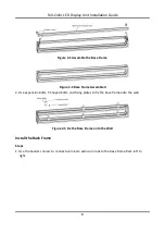
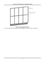
Page 11: ...ure 2 2 Base Frame Assembled 2 Use expansion bolts T Shaped bolts and fixing plates to fix the base frame onto the wall Figure 2 3 Fix the Base Frame onto the Wall Install the Rack Frame Steps 1 Use the header corners to connect aluminum extrusion rods to the base frame from left to right ...

Page 12: ...Full Color LED Display Unit Installation Guide 4 Figure 2 4 Assemble the Rack Frame 2 Use expansion bolts T Shaped bolts and fixing plates to fix the rack frame onto the wall ...

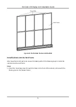
Page 13: ...Install Cabinets into the Rack Frame After base frame and rack frame are well installed perform the following steps to install the cabinets into the rack frame Steps 1 Install the mounting screws through the holes on the front of the cabinet and lock with the floating nuts on the bracket frame ...

Page 14: ...Full Color LED Display Unit Installation Guide 6 Figure 2 6 Fix the Screen ...

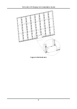
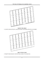
Page 15: ...allation Guide 7 Figure 2 7 Screen Fixed 2 Install the cabinets from the center to both sides until cabinets of the first row installed Figure 2 8 Screens Fixed 3 Repeat the above steps to install the other cabinets in the above rows ...

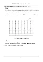
Page 16: ... after they are adjusted horizontally and vertically because the boards will probably be moved during the installation of other lamp boards Ensure that the screen is flat and without evident gap Otherwise make some adjustments Figure 2 9 Screens of the First Row Fixed Note For details about cabinet stitching see Stitch Cabinet Frames For details about lamp board installation see Install Lamp Board...

Page 17: ...wire outlet position should completely cover the bottom hole only to let the wire out to prevent the molten material from dripping to the bottom during fire caused by internal failure To ensure safety the installation parts and the wall should support four times the weight of the device 2 2 3 Install the Ultrathin Rack The ultrathin racks are used for mounting front maintenance products and back m...

Page 18: ...ure 2 11 Assemble the Base Frame Unit Figure 2 12 Base Frame Unit Assembled 2 Use wedge locking collector bolts to connect the base frame units Figure 2 13 Connect the Base Frame Units 3 Position the anchor bolts into the base frame and tighten the bolts ...

Page 19: ...on Guide 11 Figure 2 14 Assemble the Base Frame 4 Level the bottom chassis and then tighten the bolts Figure 2 15 Leveled Bottom Chassis Install the Rack Frame Steps 1 Use header corners to connect aluminum extrusion rods from bottom to top ...

Page 20: ...2 Figure 2 16 Assemble the Rack Frame Unit 2 Use wedge locking collector bolts to connect the rack frame units Figure 2 17 Connect the Rack Frame Units 3 Align the rack frame to the base chassis and use wedge locking collector bolts to fix the frames ...

Page 21: ...Full Color LED Display Unit Installation Guide 13 Figure 2 18 Align the Rack Frame to the Base Chassis Figure 2 19 Frames Aligned ...

Page 22: ... Installation Guide 14 Install the Rear Pulling Rods for Large scale Project Steps 1 Use the wedge locking collector bolts to fix the rear pulling rods into the rack frame Figure 2 20 Fix the Rear Pulling Rods into the Rack frame ...

Page 23: ... LED Display Unit Installation Guide 15 Figure 2 21 Rear Pulling Rods Fixed 2 Use the expansion bolts to fix the rear pulling rods onto the bearing wall Figure 2 22 Fix the Rear Pulling Rods onto the Bearing Wall ...

Page 24: ...to connect the screens and back connecting component which is used to connect the rack frame The following figures list three types of connectors and the positions where the connectors used respectively Figure 2 23 Connectors Figure 2 24 Connectors Installed Note Please pay attention to the types of outermost connectors between rack frame and bottom chassis ...

Page 25: ...he Connectors 3 Secure the connectors to the rack frame with screws Install Cabinets into the Rack Frame After the bottom chassis rack frame and connectors are well installed perform the following steps to install the cabinets into the rack frame Steps 1 Install the first cabinet from the lower middle part Level and secure the cabinet to the connectors on the rack frame For screens do not have con...

Page 26: ...and cabinets too tight for future adjustment In normal cases you should lock out LED lamp boards after they are adjusted horizontally and vertically because the boards will probably be moved during the installation of other lamp boards Ensure that the screen is flat and without evident gap Otherwise make some adjustments 2 Repeat the above steps to install the other cabinets in the lowest row Figu...

Page 27: ...n sheet under the bottom Do not try to resolve the deviation by hitting the cabinets on the top because it will result in larger deviation later 4 Repeat the above steps to complete the installation of other cabinets Figure 2 28 Screens Fixed 5 Ensure that all the cabinets are flat and vertical and the seams between the cabinets are even Then tighten the screws to complete the installation ...

Page 28: ...s about lamp board installation see Install Lamp Boards on the Cabinets 2 2 4 Install the All in One Rack The all in one racks are used for mounting front maintenance products and back maintenance products Install the Bottom Chassis Steps 1 Use header corners to connect aluminum extrusion rods Note It is recommended to assemble the base frame units from bottom to top ...

Page 29: ...Full Color LED Display Unit Installation Guide 21 Figure 2 30 Assemble the Base Frame Unit Figure 2 31 Base Frame Unit Assembled 2 Use wedge locking collector bolts to connect the base frame units ...

Page 30: ...Full Color LED Display Unit Installation Guide 22 Figure 2 32 Connect the Base Frame Units Figure 2 33 Base Frame Units Connected 3 Repeat the above steps to connect the other base frame units ...

Page 31: ...e frame and tighten the bolts Figure 2 35 Assemble the Base Frame 5 Level the bottom chassis and then tighten the bolts Figure 2 36 Leveled Bottom Chassis Install the Rack Frame Steps 1 Use header corners to connect aluminum extrusion rods Note It is recommended to assemble the rack frame units from bottom to top ...

Page 32: ...Full Color LED Display Unit Installation Guide 24 Figure 2 37 Assemble the Rack Frame Unit 2 Use wedge locking collector bolts to connect the rack frame units ...

Page 33: ...ion Guide 25 Figure 2 38 Connect the Rack Frame Units 3 Repeat the above steps to connect the other rack frame units Figure 2 39 Rack Frame 4 Align the rack frame to the base chassis and use wedge locking collector bolts to fix the frames ...

Page 34: ...on Guide 26 Figure 2 40 Align the Rack Frame to the Base Chassis Figure 2 41 Frames Aligned Install the Rear Pulling Rods for Large scale Project Steps 1 Use the wedge locking collector bolts to fix the rear pulling rods into the rack frame ...

Page 35: ...r LED Display Unit Installation Guide 27 Figure 2 42 Fix the Rear Pulling Rods into the Rack Frame Figure 2 43 Rear Pulling Rods Fixed 2 Use the expansion bolts to fix the rear pulling rods onto the bearing wall ...

Page 36: ... Connectors The connectors are divided into two parts customized front joint piece which is used to connect the screens and back connecting component which is used to connect the rack frame The following figures list three types of connectors and the positions where the connectors used respectively Figure 2 45 Connectors ...

Page 37: ...ermost connectors between rack frame and bottom chassis Steps 1 Twist the hexagonal screws into the screw thread plates 2 Insert the screw thread plates into the slots of aluminum extrusion rods and move the connectors to the suitable place Figure 2 47 Install the Connectors 3 Secure the connectors to the rack frame with screws ...

Page 38: ...the rear use joint pieces to fix Figure 2 48 Fix the Screen with Joint Pieces Note Install the cabinets from the bottom to the top from the middle to the sides Do not fix the screws between the connectors and cabinets too tight for future adjustment In normal cases you should lock out LED lamp boards after they are adjusted horizontally and vertically because the boards will probably be moved duri...

Page 39: ...at the cabinets are flat and vertical Note When there is a deviation in height simply place a thin iron sheet under the bottom Do not try to resolve the deviation by hitting the cabinets on the top because it will result in larger deviation later 4 Repeat the above steps to complete the installation of other cabinets ...

Page 40: ...Display Unit Installation Guide 32 Figure 2 50 Screens Fixed 5 Ensure that all the cabinets are flat and vertical and the seams between the cabinets are even Then tighten the anchor bolts to complete the installation ...

Page 41: ...about cabinet stitching see Stitch Cabinet Frames For details about lamp board installation see Install Lamp Boards on the Cabinets Install the Cover Plates and Door Plates for Bottom Chassis Steps 1 Use T Shaped bolts to install the front cover plates and lateral cover plates for bottom chassis respectively ...

Page 42: ...tion Guide 34 Figure 2 52 Install the Cover Plates 2 Use T shaped bolts or door hinge to install the door plates including upper fixing plates lower fixing plates left door plates and right door plates Figure 2 53 Install the Door Plates ...

Page 43: ...lists the load capability of a single network interface of the sending card for different screen types Table 3 1 Load Capability of Network Interfaces Screen Type Max Load of a Single Network Interface P1 2 3 cabinets P1 5 5 cabinets P1 8 7 cabinets P2 0 8 cabinets P2 5 13 cabinets Load Capability of Power Cables Table 3 2 Load Capability of Power Cables Voltage Max Load of a Single Power Cable 22...

Page 44: ... LED lamps Do not expose the device to rain or humid environment to reduce the risk of fire or electric shock Electric discharge may last for a short period of time after the power is shut down Please wait two minutes after the power is shut down to operate the device Only use the original power cable delivered with the device Contact authorized dealer to purchase power cable with same specificati...

Page 45: ... Figure 3 1 Locating Studs Locating Holes and Installation Holes Stitch Cabinet Frames Horizontally Steps 1 Align the installation holes in the horizontal direction of the two adjacent cabinet frames and adjust the cabinet frames to the relative level ...

Page 46: ...he adjacent cabinets from right to left Adjust the flatness of the cabinet frames to ensure the horizontal and vertical alignment between the cabinet frames Stitch Cabinet Frames Vertically Steps 1 Align the locating studs in the vertical direction of the two adjacent cabinet frames to the locating holes and adjust the cabinet frames to the relative level 2 Use M10 hexagon wrench to secure the bol...

Page 47: ... cabinet has 2 reserved bolts at the bottom Secure the adjacent cabinets from up to down Adjust the flatness of the cabinet frames to ensure the horizontal and vertical alignment between the cabinet frames 3 2 3 Install Lamp Boards on the Cabinets The front and back of the lamp board are shown below ...

Page 48: ...c attraction One cabinet frame is equipped with 6 lamp boards It is recommended to connect and install the 6 lamp boards for each cabinet from down to up and right to left as the figure shown below Figure 3 5 Install Lamp Board by the Specific Order Steps 1 Use signal cable to connect the cabinet and corresponding lamp and access to power source ...

Page 49: ... different kinds of lamp boards Numbers on the interfaces indicate which lamp board should be connected to lamp boards serial number refer to Figure 3 5 There are 3 long signal cables 500mm and 3 short signal cables 300mm for P1 2 to P1 6 The long signal cables should connect to position 3 5 and 6 The short signal cables should connect to position 1 2 and 4 Figure 3 6 Signal Cable Connection P1 2 ...

Page 50: ...et frames initially Note Please align the connector and pay attention to the direction of lamp boards when adsorbing the lamp board 3 Align and adsorb the lower edge of the lamp boards with the cabinet frames and then align the locating studs on the lamp boards to the locating holes on the cabinets and adsorbs the remaining three sides of the lamp boards 4 The lamp board adsorbs to the cabinet aut...

Page 51: ...e LED vacuum pumping tool and remove other lamp boards with hands Figure 3 9 LED Vacuum Pumping Tool 3 2 5 Install Protective Shield To reduce the risk of electric shock install protective shield on the exposed connector after completing LED screen installation Danger To reduce the risk of electric shock install protective shield on the exposed connector after installing LED screen ...

Page 52: ...Full Color LED Display Unit Installation Guide 44 The power cable of LED screen should be grounded before powering on the screen Before installing the protective shield ensure that the power is cut off ...

Page 53: ...g points and there are 12 adjusting points for each cabinet Figure 3 10 Points Adjustable on the Front of Cabinet Frames Chapter 4 Software Debugging 4 1 Log in to the Device In order to protect personal account privacy and reinforce system data security you need to set login password and activate the device for your first login Before you start The LED display controller client has been installed...

Page 54: ...vice is activated enter the password to log in If you forget the password reset the password using your OA account Figure 4 2 Online Device 4 Choose the device and change the IP address and gateway Note Ensure that the device resides on the same network segment with your PC client Change your PC s IP address to the device s IP address which is displayed on the LED display controller at intervals 5...

Page 55: ...een 3 Set Screen Scale according to the actual scale of the terminal and keep other parameters as the default value 4 Click Save 4 3 Configure Signal Cables Configure signal cables according to the actual receiving card connection between LED cabinets Steps Note After the screen scale is configured LED screen will show the information of signal cable connection The connection of signal cables on t...

Page 56: ...mpt shows 2 1 it indicates that the screen is the first screen connected to No 2 sending port 4 Connect signal cables Click the screen area on the right side to connect signal cables Select Line Type and select starting port and end port on the right side area 5 Right click on the right side of the interface after connection 6 Select Complete Signal Cable Connection 7 Click Save The information of...

Page 57: ...UD25946B ...

Reviews: