background image

INSTALLATION & OPERATION

FROZEN FOOD/

ICE CREAM

C A S E S

M O D E L :     K R Z H

P058479G

Rev 10  11/05

HANDBOOK

COMPONENT

Summary of Contents for KRZH

Page 1: ...INSTALLATION OPERATION FROZENFOOD ICE CREAM C A S E S MODEL KRZH P058479G Rev 10 11 05 HANDBOOK COMPONENT ...

Page 2: ......

Page 3: ...make it easier to read and to help you get the most from this innovative new design When you follow the instructions you should expect remarkable performance attractive fits and finish and long case life We are interested in your suggestions for improvement both in case design and in this handbook Please call write to Hill PHOENIX Marketing Services Department 1925 Ruffin Mill Rd Colonial Heights ...

Page 4: ......

Page 5: ...ols location and other piping tips PLUMBING PAGE 9 Information on drain connections ELECTRICAL HOOKUP AND WIRING DIAGRAMS PAGES 10 17 Complete information on electrical connections CONTROL SETTING GUIDELINE PAGE 18 Recommended settings for all case controls DEFROST AND TEMPERATURE CONTROL PAGE 19 Defrost data electric and hot gas defrost Sensor bulb locations PRODUCT LOADING PAGE 20 Air flow and l...

Page 6: ...AMAGE A claim for obvious damage must be noted on the freight bill or express receipt and signed by the carriers agent otherwise the carrier may refuse the claim CONCEALED DAMAGE If damage is not apparent until after the equipment is unpacked retain all packing materials and submit a written request to the carrier for inspection within 15 days of receipt of equipment LOST ITEMS This equipment has ...

Page 7: ... 13 16 in 19 9 cm ELECTRICAL TOP OF CASE EXTERNAL PLUMBING 20 3 4 in 52 7 cm 11 7 16 in 29 1 cm 2 13 16 in 7 1 cm 10 in 25 4 cm REFRIGERATION TOP REAR OF CASE 42 7 16 in 107 8 cm 44 5 8 in 113 3 cm 1 1 2 in 3 8 cm END 1 1 2 PVC DRAIN CONNECTION FRONT OF CASE 60 in 152 4 cm 2 DOOR 90 in 228 6 cm 3 DOOR 120 in 304 8 cm 4 DOOR 150 in 381 0 cm 5 DOOR 19 5 8 in 49 8 cm 2 DOOR 34 5 8 in 87 9 cm 3 DOOR 4...

Page 8: ...T OF CASE 36 1 2 32 1 8 89 1 4 4 3 DOOR CASE FRONT OF CASE 27 5 8 36 1 2 57 5 8 119 1 4 27 5 8 4 4 DOOR CASE FRONT OF CASE 62 1 8 36 1 2 87 5 8 149 1 4 57 5 8 4 27 5 8 5 DOOR CASE FRONT OF CASE 36 1 2 87 5 8 117 5 8 BASEHORSE LOCATION FOR MODEL KRZH ...

Page 9: ...on When ready for final line up roll the case to set position then remove casters REMOVE COTTER PIN Removing the casters is easy Simply flatten and hammer out cotter pins then lift the case with J bar and the casters will fall off CAUTION Make certain hands are out of the way KATS cases are manufactured and shipped to stores with casters installed on the base frame to make the job of moving cases ...

Page 10: ... are using was issued Also ask the points of reference from which you should take dimensions to locate the cases 2 Snap Chalk Lines Mark floor where cases are to be located for the entire lineup 3 S n a p L i n e s O n B a s e R a i l Locations Snap lines where base rails are posi tioned not the front or back edges of the cases See case cross section drawing page 3 for rail location dimen sions 6 ...

Page 11: ...te Insert top of kickplate into the upper kickplate retainer Slide the kickplate up into retainer then down on the J rail Install Pedestals The pedestals line up at the corner of the case that is located at the end of a line up Attach the pedestal to the kick plate bracket with the screws provided Add Sealant to Top Case Joint Once cases are pushed tightly together and bolted run a bead of sealant...

Page 12: ...over on the left hand side to access the refrigeration controls MODEL KRZH 44 5 8 in 113 3 cm 20 3 4 in 52 7 cm 10 in 25 4 cm REFRIGERATION TOP REAR OF CASE 42 7 16 in 107 8 cm 44 5 8 in 113 3 cm 1 1 2 in 3 8 cm END FRONT OF CASE 60 in 152 4 cm 2 DOOR 90 in 228 6 cm 3 DOOR 120 in 304 8 cm 4 DOOR 150 in 381 0 cm 5 DOOR NOTES STUB UP AREA RECOMMENDED STUB UP CENTERLINE FOR ELECTRICAL AND HUB DRAINS ...

Page 13: ...open access to the drain line area If the kickplate has been installed you will find it very easy to remove See instructions below or the line up and trim out section of this manual on page 7 LIFT UP FROM J RAIL AND PULL OUT 44 5 8 in 113 3 cm EXTERNAL PLUMBING 20 3 4 in 52 7 cm 11 7 16 in 29 1 cm 2 13 16 in 7 1 cm 42 7 16 in 107 8 cm 44 5 8 in 113 3 cm 1 1 2 in 3 8 cm END 1 1 2 PVC DRAIN CONNECTI...

Page 14: ...ELLOW PURPLE ORANGE 23 WIRING NUMBERS AND COLORS EQUIPMENT GROUNDING CONDUCTOR GREEN BLACK WHITE DOOR FRAME ANTI COND HEATERS 120 VOLT 15 16 Electrical hookups are made to a junction box located at the top left of the case For case to case wiring run green field or other conduit between junction boxes MODEL KRZH 44 5 8 in 113 3 cm 34 1 4 in 87 0 cm 7 13 16 in 19 9 cm ELECTRICAL TOP OF CASE 20 3 4 ...

Page 15: ...LAST CARRIAGE 4 REPLACE BALLAST ANTHONY 1 REMOVE CORNER BEADS 2 2 REMOVE ACCESS COVER 3 REPLACE BALLAST ARDCO ANTHONY STEPS TO REPLACE THE BALLAST 1 BALLAST COVER SCREWS 2 BALLAST COVER 1 CORNER BEAD 2 ACCESS COVER 3 BALLAST DOOR MULLION LIGHT DOOR FRAME PRISM LIGHT 3 BALLAST CARRIAGE SCREWS 2 ARE LOCATED BEHIND BALLAST COVER 4 ONCE BALLAST CARRIAGE SCREWS ARE REMOVED PULL OUT THE CARRIAGE AND REP...

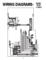
Page 16: ...12 WIRING DIAGRAMS MODEL KRZH 2 DOOR ...

Page 17: ...13 WIRING DIAGRAMS MODEL KRZH 3 DOOR ...

Page 18: ...14 WIRING DIAGRAMS MODEL KRZH 4 DOOR ...

Page 19: ...15 WIRING DIAGRAMS MODEL KRZH 5 DOOR ...

Page 20: ...16 WIRING DIAGRAMS TERMINAL BLOCK ...

Page 21: ...17 WIRING DIAGRAMS GFI ...

Page 22: ...450 Lighting Data 2 door 3 door 4 door 5 door KRZH Model 2 door 3 door 4 door 5 door Standard Fans Amps 2 20 3 30 4 40 5 50 Watts 167 250 333 417 Drain Pan Heaters 208 Volts Amps 0 86 0 86 0 86 0 86 Watts 179 179 179 179 240 Volts Amps 0 99 0 99 0 99 0 99 Watts 238 238 238 238 Anti Condensate Heaters 120 Volts Amps 6 06 8 48 10 82 12 88 Watts 727 1018 1298 1545 Fans per Case 2 3 4 5 Electrical Dat...

Page 23: ...as shown in diagram 2 which is in PLENUM COIL DISCHARGE AIR PROBE LOCATION BEHIND 3 1 2 PLUG BUTTON IN TOP FLUE HOT GAS DEFROST TERMINATION CONTROL SENSOR BULB AND PROBE LOCATION the top left hand side of the case The defrost termination control thermo stat and the temperature control thermostat are both located in thermostat enclosures behind the kickplate on the left hand side of the case as sho...

Page 24: ... overload the food product display so that it impinges on the air flow pattern MODEL KRZH DISCHARGE 1 LOAD LIMIT 2 AIR FLOW 3 RETURN AIR GRILL 4 Overloading will cause malfunction and the loss of proper temperature levels particularly when discharge and return air sections are covered Please keep products within the load limit line shown on the diagram 1 2 3 4 ...

Page 25: ...ning once a week To avoid shock hazard be sure all electrical power is turned off before cleaning In some installations more than one disconnect switch may have to be turned off to completely de energize the case Check waste outlet to insure it is not clogged before starting the cleaning process and avoid introducing water faster than the case drain can carry it away Avoid spraying cleaning soluti...

Page 26: ...ecified Do not attempt a field modification by altering the blades Fan motors may be changed with an easy two step process without lifting up the plenum thereby avoiding the necessity to unload the entire product display to make a change 1 Unplug the fan motor easily accessible out side the plenum 2 Remove two fasteners then lift out the entire fan basket 1 2 4 DOOR 5 DOOR 3 DOOR 2 DOOR Model KRZH...

Page 27: ...the case on which the part is used Length of part if applicable I E 60 90 120 or 150 Color of part if painted or color of polymer part Whether part is for left hand or right hand application Whether shelves are with or without lights Quantity Serial plate is located on top flue panel on the left hand side of the case See illustrations on page 3 3 If parts are to be returned for credit ask the Part...

Page 28: ...24 PARTS ORDERING MODEL KRZH 1 22 23 24 4 9 15 17 19 55 25 E09 E11 E10 E20 11 12 13 36 69 56 81 82 87 88 ...

Page 29: ...ckplate 25 Top Flue Panel Painted 36 Plug Button White or Black 55 Door Specify Mask Color Ardco or Anthony Door Handle Type Low or Medium Temperature Application Left or Right Hand Swing 56 Door Frame Ardco or Anthony Low or Medium Temperature Application 69 Coil 81 Bottom Wire Racks 82 Tag Moulding PVC or Aluminum 87 End Assembly Solid Custom Color Identify Left or Right hand Color of Panel and ...

Page 30: ... solution to the coating surface Using gentle pressure wipe glass over the entire surface with soft wipers once in the horizontal direction followed by once in the vertical direction Gently dry the surface of the coating with new wipers Repeat the above cleaning and drying cycle two more times Periodic Maintenance Cleaning Apply diluted cleaning solution to the coating surface Using gentle pressur...

Page 31: ... sales tax or upgrading 5 When the operation is impaired due to improper installation 6 When installation and startup forms are not properly complete or returned within two weeks after startup THIS PLAN DOES NOT COVER CONSEQUENTIAL DAMAGES Manufacturer shall not be liable under any circumstances for any consequential damages including loss of profit additional labor cost loss of refrigerant or foo...

Page 32: ... cleaning cases the following must be performed PRIOR to cleaning To avoid electrical shock be sure all electric power is turned off before cleaning In some installations more than one switch may have to be turned off to completely de energize the case Do not spray cleaning solution or water directly on fan motors or any electrical connections All lighting receptacles must be dried off prior to in...

Reviews: