background image

HANDBOOK

INSTALLATION & OPERATION

REACH-IN

BEVERAGE

C A S E S

P057333G

Rev. 12  6/06

M O D E L : O R B ,   O R B H ,

O N R B   &   O N R B H

COMPONENT

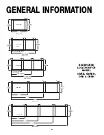
Summary of Contents for ONRB

Page 1: ...HANDBOOK INSTALLATION OPERATION REACH IN BEVERAGE C A S E S P057333G Rev 12 6 06 MODEL ORB ORBH ONRB ONRBH COMPONENT...

Page 2: ......

Page 3: ...o make it easier to read and to help you get the most from this innovative new design When you follow the instructions you should expect remarkable performance attractive fits and finish and long case...

Page 4: ......

Page 5: ...oil outlet case controls location and other piping tips PLUMBING PAGE 15 Information on drain connections ELECTRICAL HOOKUP AND WIRING DIAGRAMS PAGES 16 25 Complete information on electrical connectio...

Page 6: ...2...

Page 7: ...ice Parts Department at 1 800 283 1109 APPARENT DAMAGE A claim for obvious damage must be noted on the freight bill or express receipt and signed by the carriers agent otherwise the carrier may refuse...

Page 8: ...MATELY 1 INCH TO CASE HEIGHT z WIRING TO THE TOP ADDS APPROXIMATELY 1 INCH TO CASE HEIGHT z A 2 MINIMUM AIR GAP IS REQUIRED BETWEEN THE REAR OF THE CASE AND A WALL z SUCTION LINE ALL LENGTHS 1 2 z LIQ...

Page 9: ...M 30 7 8 in 78 4 cm 5 1 8 in 13 1 cm 16 1 16 in 40 9 cm 8 1 2 in 21 6 cm 31 9 16 in 80 2 cm 39 1 4 in 99 7 cm 85 1 16 in 216 0 cm 87 1 16 in 221 1 cm 63 in 160 1 cm 66 3 8 in 168 6 cm Door Height 68 i...

Page 10: ...RIGERATION FRONT OF CASE 10 in 25 4 cm 8 in 20 3 cm 16 1 16 in 40 8 cm 18 9 16 in 47 1 cm 27 9 16 in 70 0 cm 23 1 4 in 59 1 cm 26 7 8 in 68 3 cm 1 1 2 in 3 8 cm END 8 11 16 in 22 1 cm COIL PLENUM 23 1...

Page 11: ...89 8 cm 5 1 8 in 13 1 cm 16 1 4 in 41 3 cm 8 in 20 3 cm 24 3 16 in 61 4 cm 31 7 8 in 81 0 cm 34 5 8 in 88 0 cm 7 1 2 in 19 1 cm 1 2 BUMPER OPTION 87 1 16 in 221 1 cm 85 1 16 in 216 0 cm 63 in 160 0 cm...

Page 12: ...9 1 4 3dr CASE 95 1 4 8 CASE 3 DOOR CASE 8 CASE FRONT OF CASE 47 1 2 3dr CASE 49 1 8 8 CASE 6 4 4 4 4 4 4 4 6 23 3 16 NARROW 31 11 16 STANDARD 23 3 16 NARROW 23 3 16 NARROW 23 3 16 NARROW 31 11 16 STA...

Page 13: ...ERS MAY BE DISCARDED ROLL OUT OF TRUCK When there is a truck level delivery dock cases may be rolled directly from the truck to the store floor CAUTION If skid boards are required to unload cases cast...

Page 14: ...aser Transit Leveling is necessary to assure prop er case alignment Locate highest point on chalk line as reference for determining height of shim pack levelers A laser transit is recom mended for pre...

Page 15: ...oining case bumper BUMPER SCREW BUMPER JOINT 1 2 3 5 7 6 4 7 Remove Outriggers Remove cotter pin from outrigger by cutting tie strap Either pull the out rigger out from the front or insert a crowbar i...

Page 16: ...re adjustable to achieve almost invisible snug fit ting joints and a high level of excellence in fit and finish TRIM OUT BUMPER SCREW BUMPER JOINT 1 Adjust polymer master bumper joints if required Fir...

Page 17: ...into retainer then down on the J rail Attach the J rail which is shipped loose with the case Line up the rail with the kickplate bracket and secure with the screws provided Once the Streamlyne bumper...

Page 18: ...stallation and maintenance As the diagrams below indicates the coil outlet hole is positioned forward on the right hand side of the case fully visible in front of the fan plenum An optional piping to...

Page 19: ...has been installed you will find it very easy to remove See instruc tions below or the trim out section of this manual on page 13 C L 31 9 16 in 80 2 cm STANDARD 1 1 2 PVC DRAIN CONNECTION 33 9 16 in...

Page 20: ...E ORANGE 23 WIRING NUMBERS AND COLORS EQUIPMENT GROUNDING CONDUCTOR GREEN BLACK WHITE DOOR FRAME ANTI COND HEATERS 120 VOLT 15 16 WIRING TO TOP CONTINUOUS RACEWAY JUNCTION BOX COVER JUNCTION BOX CANOP...

Page 21: ...prism door lights are located in the door frame for Anthony door frames ANTHONY FRAMES 1 REMOVE CORNER BEADS 2 2 REMOVE ACCESS COVER 3 REPLACE BALLAST ANTHONY FRAMES STEPS TO REPLACE THE BALLAST 1 CO...

Page 22: ...POWER LEADS LAMP LEADS LAMP 1 LAMP 2 LAMP 3 FILTER BALLAST FOR LAMP 2 BALLAST FOR LAMPS 1 3 POWER LEADS LAMP LEADS LAMP 1 FILTER BALLAST FOR LAMPS 3 4 LAMP 2 LAMP 3 LAMP 4 BALLAST FOR LAMPS 1 2 2 DOOR...

Page 23: ...FOR LAMPS 4 5 LAMP 2 LAMP 3 LAMP 4 LAMP 5 BALLAST FOR LAMP 3 BALLAST FOR LAMPS 1 2 POWER LEADS LAMP LEADS LAMP 1 BALLAST FOR LAMPS 5 6 FILTER LAMP 2 LAMP 3 LAMP 4 LAMP 5 LAMP 6 BALLAST FOR LAMPS 3 4 B...

Page 24: ...20 WIRING DIAGRAMS 15 16 ORB ORBH ONRB ONRBH 2 DOOR...

Page 25: ...21 WIRING DIAGRAMS 15 16 ORB ORBH ONRB ONRBH 3 DOOR 8...

Page 26: ...22 WIRING DIAGRAMS 15 16 ORB ORBH ONRB ONRBH 4 DOOR 12...

Page 27: ...IXTURE TYP LAMP 4 LAMP 3 RACEWAY BLUE YELLOW YELLOW BLACK BLUE WHITE BLACK WHT BLK BALLAST WHT BLK BALLAST 15 ANTI 16 COND HEATERS WHITE BLACK BLACK WHITE SCAN X SENSOR BUTTON LOC TOP CASE LIGHT BIMET...

Page 28: ...LAMP 3 RACEWAY BLUE YELLOW YELLOW BLACK BLUE WHITE BLACK WHT BLK BALLAST WHT BLK BALLAST 15 ANTI 16 COND HEATERS WHITE BLACK BLACK WHITE CASE LIGHT BIMETAL DISC THERMOSTAT BLACK CASE LIGHT SWITCH EVA...

Page 29: ...25 WIRING DIAGRAMS GFI...

Page 30: ...04 3 High efficiency fans reduce refrigeration load by 96 BTUHs fan 4 Average discharge air velocity at peak of defrost 8303 8003 BTUH door2 Model 32 34 Evaporator F 36 38 38 40 Return Air F 380 380 D...

Page 31: ...s 120 Volts Amps 0 31 0 46 0 61 0 77 0 92 0 70 0 93 Watts 18 4 27 6 36 8 46 0 55 2 42 56 Electrical Data ORBH Model 120 Volts 6 If timed off defrost is utilized If electric or hot gas defrost is utili...

Page 32: ...or 3 door 4 door 5 door Standard Fans Amps 1 00 1 50 2 00 2 50 Watts 60 90 120 150 Defrost Heaters 208 Volts Amps 4 39 4 96 6 51 7 96 Watts 914 1032 1355 1655 240 Volts Amps 5 06 5 71 7 55 9 17 Watts...

Page 33: ...med off defrost is utilized If electric or hot gas defrost is utilized case only requires 1 defrost per day 7 NOTE not an option on this case model Electric Defrost Defrosts Per Day 46 Model ONRBH Fai...

Page 34: ...own in diagram 2 below which is in the front left hand side of the case The defrost termination control thermostat and the temperature control thermostat are located inside the junction box on the low...

Page 35: ...the food product display so that it impinges on the air flow pattern DISCHARGE 1 LOAD LIMIT 2 AIR FLOW 3 RETURN AIR GRILL 4 Overloading will cause malfunction and the loss of proper temperature levels...

Page 36: ...ning In some installations more than one disconnect switch may have to be turned off to completely de energize the case Check waste outlet to insure it is not clogged before starting the cleaning proc...

Page 37: ...ed Do not attempt a field modification by altering the blades Fan motors may be changed with an easy two step process without lifting up the plenum thereby avoiding the necessity to unload the entire...

Page 38: ...34 PARTS ORDERING 23 24 11 9 1 2 17 88 E02 E01 55 4 87 10 15 20 23 E08 E09 E11 E10 E20 12 13 69 81 82 83 25 56 78...

Page 39: ...rear 24 J Rail for Kickplate 25 Top Flue Panel Painted 36 Plug Button Not Shown 55 Door Specify Mask Color Ardco or Anthony Door Handle Type Low or Medium Temperature Application Left or Right Hand S...

Page 40: ...ase on which the part is used Length of part if applicable I E 60 90 120 150 or 180 Color of part if painted or color of polymer part Whether part is for left hand or right hand application Whether sh...

Page 41: ...solution to the coating surface Using gentle pressure wipe glass over the entire surface with soft wipers once in the horizontal direction followed by once in the vertical direction Gently dry the sur...

Page 42: ...38 NOTES...

Page 43: ...sales tax or upgrading 5 When the operation is impaired due to improper installation 6 When installation and startup forms are not properly complete or returned within two weeks after startup THIS PLA...

Page 44: ...cleaning cases the following must be performed PRIOR to cleaning To avoid electrical shock be sure all electric power is turned off before cleaning In some installations more than one switch may have...

Reviews: