background image

INSTALLATION & OPERATION

C A S E S

HANDBOOK

P055547D

Rev. 10  11/05

M O D E L :   O N I Z

FROZEN FOOD/

ICE CREAM

COMPONENT

Summary of Contents for ORIGIN2 ONIZ
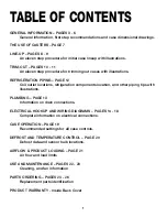
Page 1: ...INSTALLATION OPERATION C A S E S HANDBOOK P055547D Rev 10 11 05 MODEL ONIZ FROZENFOOD ICECREAM COMPONENT...

Page 2: ......

Page 3: ...ions to make it easier to read and to help you get the most from this innovative new design When you follow the instructions you should expect remarkable performance attractive fits and finish and lon...

Page 4: ......

Page 5: ...efrigeration components location and other piping tips with illustrations PLUMBING PAGE 13 Information on drain connections ELECTRICAL HOOKUP AND WIRING DIAGRAMS PAGES 14 18 Complete information on el...

Page 6: ...2...

Page 7: ...9 APPARENT DAMAGE A claim for obvious damage must be noted on the freight bill or express receipt and signed by the carriers agent otherwise the carrier may refuse the claim CONCEALED DAMAGE If damage...

Page 8: ...22 9 cm ELECTRICAL WIRING TO RACEWAY STANDARD 1 1 2 PVC DRAIN CONNECTION FRONT OF CASE 12 15 16 in 32 9 cm 22 1 2 in 57 1 cm 17 3 8 in 44 1 cm 9 11 16 in 24 6 cm 14 1 4 in 36 1 cm REFRIGERATION 6 1 2...

Page 9: ...8 cm FLAT END 6 in 15 2 cm 9 in 22 9 cm ELECTRICAL WIRING TO RACEWAY STANDARD 1 1 2 PVC DRAIN CONNECTION FRONT OF CASE 12 15 16 in 32 9 cm 22 1 2 in 57 1 cm 17 3 8 in 44 1 cm 9 11 16 in 24 6 cm 14 1 4...

Page 10: ...19 1 2 95 1 4 143 1 4 54 1 8 97 13 32 49 1 2 8 CASE 12 CASE FRONT OF CASE FRONT OF CASE 19 1 2 4 4 6 GENERAL INFORMATION BASE HORSE LOCATIONS FOR MODELS ONIZ...

Page 11: ...inal line up roll the case to set position then remove casters REMOVE COTTER PIN Removing the casters is easy Simply flatten and hammer out cotter pins then lift the case with J bar and the casters wi...

Page 12: ...s to locate the cases Set Shims On Joint Locations Locate case joint positions along chalk lines Spot shim packs at each joint location and at each base horse between the joints 2 Snap Chalk Lines Mar...

Page 13: ...ad of sealant around entire end before pushing cases tightly together 8 Position Next Case In Line Up Roll the next case approximately 2 from the adjoining case Remove casters on the end nearest to th...

Page 14: ...r right to close seam as required Bumper joint neat ly finishes any gap that may remain 4 Slide bumper joint to center of joint between the two cases Use screw driver in hole provided 3 Adjust polymer...

Page 15: ...se with the case Line up the rail to the kickplate brack ets and secure with the screws pro vided 8 Attach pedestals Locate the pedestals which are shipped loose with the case Attach the pedestals to...

Page 16: ...minimizing the need to unload product Be sure to reseal the outlet hole after installation using a canned foam sealant and white RTV C L C L C L 45 in 114 2 cm 22 1 2 in 57 1 cm 17 3 8 in 44 1 cm 9 11...

Page 17: ...cess to the drain area can be easily obtained by removing it See the diagram below and the Trim Out section of this manual on page 11 HOW TO REMOVE KICKPLATE C L C L C L 45 in 114 2 cm 22 1 2 in 57 1...

Page 18: ...TERMINATION CONTROL 120 VOLT WHITE 3 4 13 14 19 20 21 WHITE BLACK YELLOW YELLOW PURPLE ORANGE 23 WIRING NUMBERS AND COLORS EQUIPMENT GROUNDING CONDUCTOR GREEN C L C L C L 45 in 114 2 cm 22 1 2 in 57...

Page 19: ...15 WIRING DIAGRAMS MODEL ONIZ 6...

Page 20: ...16 WIRING DIAGRAMS MODEL ONIZ 8...

Page 21: ...17 WIRING DIAGRAMS MODEL ONIZ 10...
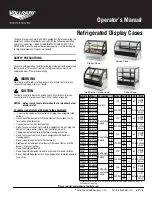
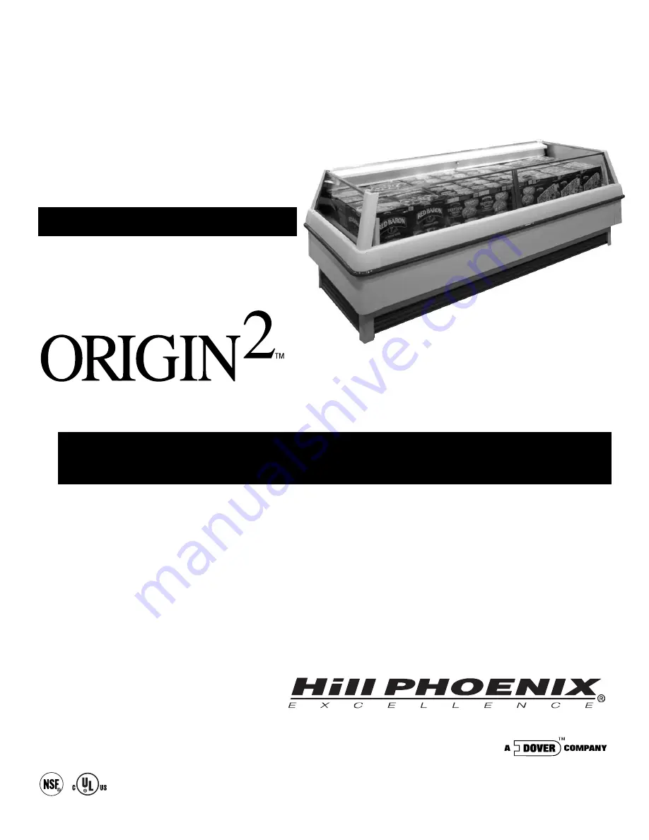
Page 22: ...18 WIRING DIAGRAMS MODEL ONIZ 12...

Page 23: ...lectric Defrost Defrosts Per Day 2 Model ONIZ Fail safe min 35 Termination Temp F 47 Defrost Controls Timed Off Defrost Fail safe min Termination Temp F Hot Gas Defrost Fail safe min 20 Termination Te...

Page 24: ...defrost termination control thermostats are located in the electrical raceway as shown in diagram 1 below The temperature control and the electric defrost ter mination control sensor bulbs are locate...

Page 25: ...verload the food product display so that it blocks the air flow pattern 1 2 3 4 Overloading will cause malfunction and the loss of proper temperature levels particularly when discharge and return air...

Page 26: ...de energize the case Check waste outlet to insure it is not clogged before starting the cleaning process and avoid introducing water faster than the case drain can carry it away Avoid spraying cleanin...

Page 27: ...nt that the blade pitch be maintained as speci fied Do not attempt a field modification by alter ing the blades Fan motors may be changed with an easy two step process without lifting up the plenum th...

Page 28: ...24 PARTS ORDERING 18 1 26 2 17 3 30 5 14 48 12 15 9 E01 24 11 6 31 MODEL ONIZ 37 69 74 59 73 E09 E11 E10 E20...

Page 29: ...18 Pedestal Painted 24 J Rail for Kickplate 26 Front Panel Painted 30 Corner Bumper Featherstone Smoke White French Vanilla Black 31 Corner Casting for Solid Panel and Glass Front Extensions 37 Corne...

Page 30: ...you are ordering Model number and serial number of the case which the part is needed for Length of part if applicable I E 6 8 10 12 Color of part if painted or color of polymer part Quantity Serial p...

Page 31: ...sales tax or upgrading 5 When the operation is impaired due to improper installation 6 When installation and startup forms are not properly complete or returned within two weeks after startup THIS PLA...

Page 32: ...cleaning cases the following must be performed PRIOR to cleaning To avoid electrical shock be sure all electric power is turned off before cleaning In some installations more than one switch may have...

Reviews: