background image

DELI

C A S E S

M O D E L :     O S A A

HANDBOOK

INSTALLATION & OPERATION

9/03

P061773M

Summary of Contents for Origin2 OSAA

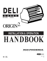
Page 1: ...DELI C A S E S MODEL OSAA HANDBOOK INSTALLATION OPERATION 9 03 P061773M...

Page 2: ......

Page 3: ...o make it easier to read and to help you get the most from this innovative new design When you follow the instructions you should expect remarkable performance attractive fits and finish and long case...

Page 4: ......

Page 5: ...self contained deli case COMPONENT DEFINITIONS PAGE 11 Operational descriptions of the refrigeration components PLUMBING PAGE 12 Information on drain connections ELECTRICAL HOOKUP WIRING DIAGRAMS AND...

Page 6: ...PPARENT DAMAGE A claim for obvious damage must be noted on the freight bill or express receipt and signed by the carriers agent otherwise the carrier may refuse the claim CONCEALED DAMAGE If damage is...

Page 7: ...cm 5 13 16 in 14 7 cm 38 5 16 in 97 3 cm 49 1 16 in 124 6 cm 34 1 2 in 87 6 cm ELECTRICAL JUNCTION BOX STANDARD 25 9 16 in 64 9 cm 28 1 16 in 71 2 cm 1 1 2 PVC DRAIN CONNECTION FRONT OF CASE 1 1 2 in...

Page 8: ...31 11 16 71 1 4 4 6 CASE FRONT OF CASE 4 GENERAL INFORMATION BASEHORSE LOCATIONS FOR MODEL OSAA...

Page 9: ...r final line up roll the case to set position then remove casters REMOVE COTTER PIN Removing the casters is easy Simply flatten and hammer out cotter pins then lift the case with J bar and the casters...

Page 10: ...O n B a s e R a i l Locations Snap lines where base rails are posi tioned not the front or back edges of the cases See case cross section drawing pages 3 4 for rail location dimensions 4 Level Floor...

Page 11: ...Accessories From Case Add Sealant Remove anything from case that may interfere with case joining eg ship ping braces Run a bead of sealant around entire end before pushing cases tightly together 7 1 3...

Page 12: ...1 Tighten all joint bolts Draw up tightly but do not over tighten 2 Adjust polymer master bumper joints if required First loosen bumper screws 3 Slide bumper joint to the center of the joint between t...

Page 13: ...be slid on the rear sill first then the top lip fits between the rear sill and the mullion Secure the joint underneath the rear sill with the screws provided 14 Install the J rail onto the case base r...

Page 14: ...and deck pan which minimizes the need to remove product The diagram below illustrates all of the refrigeration components in the OSAA 6 case The components surrounded by the box are located within the...

Page 15: ...aid heat transfer Filter Drier A device installed on the liquid line of a refrigeration system that removes water and other impurities from the refrigerant in the lines during initial start up High P...

Page 16: ...ve drain pan at the owners option The kickplate is shipped loose with the case for field installation therefore you should have open access to the drain line area If the kickplate has been installed y...

Page 17: ...16 in 64 9 cm 28 1 16 in 71 2 cm FRONT OF CASE 1 1 2 in 3 8 cm END 21 1 2 in 54 6 cm NOTES RECOMMENDED STUB UP CENTERLINE FOR ELECTRICAL AND HUB DRAINS C L 72 in 182 9 cm 6 case MODEL OSAA 6 REAR SIL...

Page 18: ...Interval 0 to 99 hours dd Maximum Defrost Duration 1 to 99 min dC Dripping Time After Defrost 0 to 99 min dU Initial Defrost Interval time before first defrost after startup 0 to 99 min dP Defrost Di...

Page 19: ...e beginning self test Cycle power to resume operation Press the Up and the Down buttons in sequence and hold for 5 seconds To Initiate Self Test Press and the Enter and Up buttons in sequence and hold...

Page 20: ...K WHITE YELLOW YELLOW OPT DEFROST 120V FANS 208 240V 120V WHITE RED BLUE SW1 PURPLE RED TEMP PROBE LOCATION RETURN AIR DEFROST PROBE LOCATION COIL SOLENOID VALVE COIL DRAIN PAN RECEPTACLE DUAL PRESSUR...

Page 21: ...e min Termination Temp F Fail safe min 4 Termination Temp F Fail safe min 35 Termination Temp F 49 2 RLA Running Load Amps 3 LRA Locked Rotor Amps Guidelines Control Settings 1 Average discharge air v...

Page 22: ...ent may be required depending on store conditions These cases are equipped with Electric Defrost The sensor bulb and probe for electric defrost termination and the sensor bulb for temperature control...

Page 23: ...do not overload the food product display so that it impinges on the air flow pattern DISCHARGE 1 LOAD LIMIT 2 AIR FLOW 3 RETURN AIR GRILL 4 MODEL OSAA Overloading will cause malfunction and the loss o...

Page 24: ...gize the case Check waste outlet to insure it is not clogged before starting the cleaning process and avoid introducing water faster than the case drain can carry it away Avoid spraying cleaning solut...

Page 25: ...hat the blade pitch be maintained as spec ified Do not attempt a field modification by altering the blades Fan motors may be changed with an easy two step process without lifting up the plenum thereby...

Page 26: ...E10 E11 E09 23 11 24 9 1 26 2 17 88 87 22 5 28 20 3 48 53 55 56 46 9a 69 21 29 36 42 49 E01 77 81 82 66 PARTS ORDERING MODEL OSAA 22 50 E06 E07 E09 E11 E10 E20...

Page 27: ...Stainless Steel 54 Inside Mullion Cover Not Shown 55 Doors Specify Outside or Inside when ordering 56 Door Frame 62 Light Rod Cover Not Shown 66 Front Extensions Inside and Outside 69 Coil Specify up...

Page 28: ...mber of the case on which the part is used Length of part if applicable I E 6 Color of part if painted or color of polymer part Whether part is for left hand or right hand application Whether shelves...

Page 29: ...25 NOTES...

Page 30: ...26 NOTES...

Page 31: ...sales tax or upgrading 5 When the operation is impaired due to improper installation 6 When installation and startup forms are not properly complete or returned within two weeks after startup THIS PLA...

Page 32: ...e When cleaning cases the following must be performed PRIOR to cleaning To avoid electrical shock be sure all electric power is turned off before cleaning In some installations more than one switch ma...

Reviews: