background image

LIGHT TRUCK MATERIAL SPREADER

MODELS 825, 815, 625, 615

OPERATOR’S MANUAL

DO NOT USE OR OPERATE THIS EQUIPMENT UNTIL THIS MANUAL

HAS BEEN READ AND THOROUGHLY UNDERSTOOD

PART NUMBER 79202499 Rev. C

Summary of Contents for 615

Page 1: ...LIGHT TRUCK MATERIAL SPREADER MODELS 825 815 625 615 OPERATOR S MANUAL DO NOT USE OR OPERATE THIS EQUIPMENT UNTIL THIS MANUAL HAS BEEN READ AND THOROUGHLY UNDERSTOOD PART NUMBER 79202499 Rev C ...

Page 2: ......

Page 3: ... 10 Throttle Control Actuator 11 Lubrication 11 12 Electric Clutch Trouble Shooting Clutch Problems 13 INSTALLATION INSTRUCTIONS 14 15 OPTIONAL EQUIPMENT 16 18 PARTS BREAKDOWN 19 24 Engine Assembly 19 Electrical Assembly 20 Discharge Chute Assembly 21 Hopper Assembly 22 23 Front Shaft Apron Chain 24 SPECIFICATIONS 25 ELECTRICAL SCHEMATIC DIAGRAM 26 WARRANTY 27 Table of Contents 1 79202499 Rev C 3 ...

Page 4: ... dealer This is the safety alert symbol It alerts an operator to information concerning personal safety Always observe and heed these instructions otherwise death or serious injury can result All references to LEFT or RIGHT mean viewing the spreader from the rear and facing the truck This Operator s manual is shipped with this equipment Contact your Hiniker dealer for ad ditional copies Always obt...

Page 5: ...ot use side extensions on your spreader to increase salt storage capacity Using side exten sions may damage hopper and cause injury to personnel SAFETY 9 Do not drive motor vehicle with swing away chute open or unlatched Make sure swing away chute is fully engaged in its working position or damage to your spreader chute may occur 10 Make sure the spreader is securely fastened to the vehicle in acc...

Page 6: ...pprox Very Coarse Rock Salt 950 Coarse Rock Salt 1 215 Coarse Sand Dry 2 565 Coarse Sand Wet 3 240 Calculate total material weight by multiplying pounds per cubic yard by cubic yards of mate rial Local state and federal regulations may require flashing lights center high mounted stop light or other additional equipment for operation on public roadways It is the owners responsibil ity to know and f...

Page 7: ...er switch in the RUN position CAUTION If the battery has been re moved and machine is to be hand started be sure the positive cable red at the battery end has the terminal taped to prevent sparking to ground when the engine is running The electric clutch can be engaged or disen gaged at any engine speed However since engagement time and torque is almost instanta neous to prevent premature spinner ...

Page 8: ...D 1 2 DWG NO 6021 SPREAD CONTROL Thickness of material cover is controlled by four variables 1 Feedgate Setting Raising or lowering the feedgate will in crease or decrease the amount of mate rial delivered to the spinner for any given conveyor speed Gate openings range from 3 8 to 4 1 4 DWG NO 6019 To set the feedgate position loosen the nut at location 1 Use the feedgate handle to move the feedga...

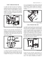
Page 9: ...ully engaged the spring pin on the spinner shaft If it is not engaged turn the spinner shaft until the spring pushes the coupler over the spinner shaft and the coupler engages the spring pin A fully engaged spinner will look like the above drawing SLIDE REARWARD 2 3 1 DWG NO 6024 LONG SPINNER OPERATION To utilize this option pull the pin at location 1 and allow the chute to swing open This disenga...

Page 10: ...ng condition 1 Disconnect and remove the battery from the spreader Apply a light coat of dielectric grease to all electrical terminals and cap or tape loose terminals to prevent damage or corrosion 2 Wash the spreader to flush out any remain ing material 3 Inspect for worn or damaged components Repair or replace as needed 4 Grease all bearings Grease points are identified in the Maintenance Servic...

Page 11: ... 3 24 47 5 Loose bolts can cause hole elongation and part failure resulting in dangerous operating condi tions and equipment breakdown Check all hardware periodically during opera tion and keep tightened to specified torques Replace worn bolts and locknuts with Grade 5 bolts and equivalent type B or F locknuts Type B locknuts are plain hex type F locknuts are flanged hex Fill electrical connectors...

Page 12: ... at location 1 and allow the spinner to swing open Loosen the 4 nuts at location 2 that secure the upper bearings which hold the upper spin ner shaft Slide the top spinner shaft away from the gearbox to tighten the chain Make sure the shaft is vertical before retightening the hard ware Rotate the chute assembly and reinsert the pin at location 1 Loosen the 4 nuts at location 3 that secure the bear...

Page 13: ...ubricate adjust or clean the machine while it is running Death or serious injury can result Prior to operation of a new machine or one that has been stored grease all bearing points with a high quality SAE multi purpose grease and oil the roller chains Throughout the season grease bearings at about 10 hour intervals and oil roller chains of ten NOTE Over greasing may cause seal damage to bearings ...

Page 14: ...12 Maintenance Service Procedures GREASE POINT LOCATIONS DWG NO 6029 DWG NO 6030 Spinner Grease Point Locations ...

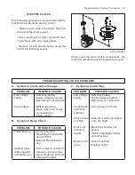
Page 15: ...ty charging system Bad wiring or connectors Broken lead wire Open clutch coil check coil resistance Faulty switch B Symptom Noisy Clutch PROBLEM POSSIBLE CAUSES Failed bearing Adapter plate rattles against antirotation pin Loose mounting Operating Temperature above 250O F Bearing Preloaded Axi ally Some noise is normal to reduce noise level iso late antirotation pin from frame with rubber C Sympto...

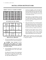
Page 16: ... battery top screen inverted vee may affect this balance point INSTALLATION INSTRUCTIONS 3 Center the spreader on the truck with the rear rails extending about 12 14 inches be hind the furthest point of interference back of the truck bumper trailer hitch etc Verify the rear legs of the spreader rest securely on the bed of the truck Place lumber as needed between the back of the truck cab and the f...

Page 17: ...ntil it is aligned with the top shaft and the coupler engages the spinner shaft spring pin Again when the shafts are aligned the cou pler on the upper shaft will slide over the bottom shaft and the spring pin will engage the slot in the coupler The bottom shaft may need to be rotated slightly to align the slot in the coupler with the spring pin Check that the bottom shaft is vertical be fore retig...

Page 18: ...rap Strap SS 1 1 1 1 2 2 3 4 5 950 001 089 031 09103 951 005 003 951 003 013 79202743 79202744 Hex Head Cap Screw 3 8 16 x 3 4 Hex Head Cap Screw 3 8 16 x 3 4 SS Lock Nut 3 8 16 Nylon Insert Lock Nut 3 8 16 Nylon Insert SS Inverted V Gusset Inverted V Gusset SS 12 12 12 12 2 2 DWG NO 6305 Adjustable Inverted V Kit No 79202394 6 1 2 FT Hopper SS Adjustable Inverted V Kit No 79202042 8 FT Hopper Adj...

Page 19: ...36 79203146 950 001 089 951 002 003 Lock Nut 5 16 18 Mac Lock Middle Grid Support Hex Head Cap Screw 3 8 16 x 3 4 Gr 5 Whiz Lock Nut 3 8 16 6 1 2 2 TARP KIT DWG NO 6460 79203036 6 1 2 Foot Sander Tarp Assembly 79203037 8 Foot Sander Tarp Assembly REF NO PART NUMBER DESCRIPTION QTY REF NO PART NUMBER DESCRIPTION QTY 1 2 3 79203033 79203032 79203031 79203029 Tarp Shurco 8 Sander Tarp Shurco 6 1 2 Sa...

Page 20: ... DESCRIPTION QTY REF NO PART NUMBER DESCRIPTION QTY 1 79202400 Ratchet Tiedown 4 BRAKE LIGHT KIT DWG NO 3674 79202581 Brake Light Assembly REF NO PART NUMBER DESCRIPTION QTY REF NO PART NUMBER DESCRIPTION QTY 1 2 79202091 79202092 Lamp Grommet 1 1 3 79202093 79202089 Plug Brake Light Assembly 1 ...

Page 21: ... Starter Solenoid Muffler Deflector Hex Head Cap Screw 5 16 18 x 1 1 4 Gr 5 Hex Head Cap Screw 5 16 18 x 1 1 4 SS 1 1 1 1 1 1 1 1 1 2 1 1 4 4 12 13 14 15 16 17 18 19 20 950 003 002 950 003 077 951 005 036 951 003 015 950 002 003 950 001 345 060954 061605 950 004 031 951 003 011 79201995 950 005 027 952 003 010 952 004 062 Carriage Bolt 5 16 18 x 1 2 Gr 5 Carriage Bolt 5 16 18 x 5 8 SS Mac Lock Nut...

Page 22: ...nsole Extension Wiring Harness Engine 3 Wire Assembly Negative Battery Black Wire Assembly Positive Battery Red 8 Cable Tie See Page 22 1 1 1 1 1 1 2 1 9 10 11 12 13 14 15 16 79202397 79202084 38812023 300 14002 951 001 003 392 010 028 715 02536 38812016 Electrical Actuator Starter Solenoid Cable Assembly Solenoid To Starter Terminal Ring 5 16 Hex Nut 1 4 20 Self Tapping Screw 8 32 x 1 2 Shw Head ...

Page 23: ... Bolt 5 16 18 x 5 8 Gr 5 Carriage Bolt 5 16 18 x 3 4 SS 1 1 1 1 3 3 1 1 1 1 1 1 1 1 1 1 1 1 2 1 1 1 1 1 1 A R A R 14 15 16 17 18 19 20 21 22 23 24 25 26 27 28 29 951 005 003 951 003 013 951 005 036 951 003 015 79202483 701 35103 953 005 005 950 001 296 950 001 315 950 001 117 950 001 319 952 002 011 952 004 062 951 005 089 061605 950 002 014 950 001 344 952 002 003 952 002 013 715 04017 79202518 7...

Page 24: ...22 Parts Breakdown HOPPER ASSEMBLY DWG NO 6035 ...

Page 25: ...1 1 1 1 1 A R A R A R A R A R A R 2 2 2 A R A R 1 1 1 A R A R A R A R 1 1 1 2 1 1 1 2 1 1 1 1 2 2 2 2 2 4 4 4 4 2 2 1 1 1 1 1 1 1 1 37 38 39 40 41 42 43 44 45 46 47 48 49 50 51 52 53 54 55 56 57 58 59 60 61 62 63 64 65 66 67 68 69 70 71 72 73 74 75 76 79202523 79202455 79202456 953 003 003 79202464 79202741 79202474 79202519 79202454 030 16041 950 003 080 951 005 036 951 002 011 79202458 79202524 ...

Page 26: ...IPTION QTY 1 2 3 4 000 28670 953 001 016 000 28666 79202570 Coupler Link Pin Cotter Pin 1 8 x 1 2 Long Chain Link With Pins Repair Only Slat With Welded LinksAnd Pins Repair Only A R A R A R A R 5 6 79202398 79202399 79202459 Apron Chain Assembly 8 Hopper Apron Chain Assembly 6 1 2 Hopper Idler Shaft Weldment 1 1 1 ...

Page 27: ... lbs Approximately Weight Model 625 Hopper Only 494 lbs Approximately Weight Model 615 Hopper Only 550 lbs Approximately CONVEYOR Trough Width 13 Inches Flight Bars 3 16 X 3 4 on 11 9 16 Inch Centers MODELS 825 815 625 615 8 6 1 2 Engine Mechanical Drive 10 5 HP Air Cooled 4 Cycle OHV Gasoline Engine 12 Volt Electric Starter with Alternator 3 Quart Fuel Tank Electric Throttle Control 1600 RPM to 3...

Page 28: ...26 Electrical Schematic ELECTRICAL SCHEMATIC DWG NO 6038 ...

Page 29: ...titution of parts not approved by Hiniker Company or any alteration or repair in such manner as in our judgment affects the product materially and adversely shall void this warranty Hiniker reserves the right to make improvements or changes to any of it s products without notice Such improvements or changes shall not trigger any obligation by Hiniker to update modify or change any products previou...

Reviews: