background image

HINIKER SNOW PLOW

HYDRAULIC UNIT

POWER UNITS

DB-7929-1, DB-7929-2 & DB-7929-3

SERVICE MANUAL

DO NOT USE OR OPERATE THIS EQUIPMENT UNTIL THIS MANUAL

HAS BEEN READ AND THOROUGHLY UNDERSTOOD

PART NUMBER 25012811

Summary of Contents for DB-7929-1

Page 1: ...NIKER SNOW PLOW HYDRAULIC UNIT POWER UNITS DB 7929 1 DB 7929 2 DB 7929 3 SERVICE MANUAL DO NOT USE OR OPERATE THIS EQUIPMENT UNTIL THIS MANUAL HAS BEEN READ AND THOROUGHLY UNDERSTOOD PART NUMBER 25012811 ...

Page 2: ......

Page 3: ...ower circuit does not however pressure is generated in the lower circuit as fluid returns to the reservoir Raise Mode Of Operation Operating the Raise switch energizes the 12 VDC Motor and de energizes the raise lower so lenoid Hydraulic fluid under pressure is then di rected through the Neutral position of the angle left right spool valve and a one way check valve to the lift cylinder Releasing t...

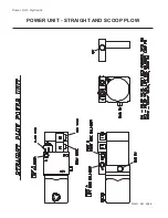
Page 4: ...Power Unit Hydraulic POWER UNIT STRAIGHT AND SCOOP PLOW DWG NO 6586 ...

Page 5: ...Power Unit Hydraulic Circuit Diagram POWER UNIT HYDRAULIC CIRCUIT DIAGRAM DWG NO 4180A ...

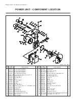
Page 6: ...f Valve Kit Adjustable Relief Valve 0 Ring Motor 12V DC Motor Brush Kit 1 1 1 2 2 1 1 1 1 1 1 1 4 1 1 1 1 1 1 1 19 20 21 22 23 24 25 26 27 28 29 30 31 32 33 34 35 36 37 25012673 952 001 001 951 001 003 25011654 25011667 25010544 25010992 25012674 25012677 25010746 25010762 25012686 25012685 25012684 25012683 25012688 25012687 950 004 115 952 004 080 Ground Stud Lock Washer 1 4 Inch Hex Nut 1 4 20 ...

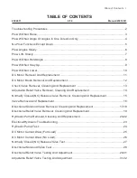
Page 7: ...table Relief Valve Removal Cleaning And Replacement 14 Normally Closed NC Release Valve Removal Cleaning And Replacement 15 Valve Removal And Replacement 16 Directional Solenoid Valve Removal Cleaning And Replacement 17 18 Directional Relief Valve Removal Cleaning And Replacement 19 Hydraulic Pump Removal Cleaning And Replacement 20 22 Electrical Hydraulic Troubleshooting 23 Hydraulic Pump Test 24...

Page 8: ...on or dirt in and or on Pins and Sockets B Damaged or missing Pins and or Sockets C Full engagement of Pins into respective Sockets 4 Check Ground A Make sure battery ground to vehicle frame is clean corrosion free and tight B Make sure that ground connections from the Snow Plow harness to vehicle frame or battery are clean corrosion free and tight 5 Verify the correct hydraulic fluid is being use...

Page 9: ...y holding metal end of screwdriver within 1 8 of the nut end of NC Release Valve Coil Is screwdriver attracted to nut end of coil Refer to electrical troubleshooting Does pump motor run Remove inspect and clean Adjustable Re lief Valve Repair or replace as necessary See page 14 Reinstall and adjust See page 31 32 Does plow raise Call Hiniker Service Does Plow Raise Call Hiniker Service Yes No No Y...

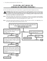
Page 10: ...Always lower the unit and relieve pressure before removing any lines or caps Allow the system to cool down before draining oil or handling system components Serious burns can result from contact with hot oil Note If the plow angles only one way when the joystick is moved in any direction except Down The directional solenoid valves is stuck and holding the valve in that position see Directional Sol...

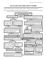
Page 11: ...oid back to joystick control ler Replace or repair as required Does plow operate correctly Yes No End End Check Starter Solenoid Mount Plate for ground Is ground good Yes No Check 24 black wire Ensure Starter Sole noid is connected to good vehicle ground ei ther directly or through 24 black wire Replace Starter Solenoid Does plow operate correctly Yes No End Remove inspect and clean Pump See page ...

Page 12: ...air or replace as nec essary Does plow angle fully left and right from center in approximately 2 seconds Yes No Yes No End Yes No Note Until pump system warms slow functioning of the V Plow will occur in extremely cold tempera tures unless a high quality oil that is appropriate for the temperatures in which you will be plow ing snow is used See chart below Note Ensure vehicle battery is fully char...

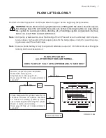
Page 13: ...y Does plow lift fully up in approximately 2 seconds Yes No Yes No End Yes No Note Until pump system warms slow functioning of the V Plow will occur in extremely cold tempera tures unless a high quality oil that is appropriate for the temperatures in which you will be plow ing snow is used See chart below Note Ensure vehicle battery is fully charged and alternator output is 13 6 Volts minimum with...

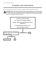
Page 14: ...SURE SEE PAGE 29 30 DOES PLOW HOLD ANGLE Remove inspect and clean Directional Valve See page 17 18 Does plow hold angle Yes No Yes No End End Call Hiniker Service WARNING Never disconnect any hydraulic line or fitting with the unit in the raised posi tion Always lower the unit and relieve pressure before removing any lines or caps Allow the system to cool down before draining oil or handling syste...

Page 15: ...est light Is voltage present Yes No Yes No End Refer to electrical troubleshooting Does Plow Stay Up Yes No End Yes No Call Hiniker Service End PLOW WILL NOT STAY UP Perform all initial inspections and checks listed on page 2 before beginning test procedure WARNING Never disconnect any hydraulic line or fitting with the unit in the raised posi tion Always lower the unit and relieve pressure before...

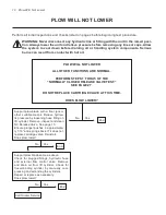
Page 16: ...w blade same as above Check for plugged fittings hydraulic hose and external flow control valve Remove and drain oil from lift cylinder Check for frozen binding cylinder by manually com pressing and extending the cylinders Repair or replace as necessary Does plow lower Yes No Yes No End Yes No End End PLOW WILL NOT LOWER Perform all initial inspections and checks listed on page 2 before beginning ...

Page 17: ...nto three pieces and will require additional time to reas semble Hold motor together while removing it from the end head NOTE If oil is found in the cavity of the valve passage where the coupling is located replace ment of the oil pump shaft seal is necessary be fore the unit can be put back into service See page 20 PHILLIPS HEAD SCREWS MOTOR CAP MOTOR MOTOR TERMINAL POS GROUND SCREW NEG COUPLING ...

Page 18: ...brushes with bare wires Ground brushes and two 2 brushes with insulated wires POS brush es make sure that you note location of the two types and replace them with like type brushes WARNING Failure to replace Brushes correctly will severely damage Motor and may cause electrical fires FAIL URE TO HEED CAN RESULT IN SERIOUS IN JURY OR DEATH PHOTO NO 1000326 Remove screws from brush leads Carefully pr...

Page 19: ...tem components Serious burns can result from contact with hot oil PHOTO NO 1000298A Remove the check valve body with a 7 8 hex socket PHOTO NO 10002317 Inspect the check valve O rings for wear and contamination Replace if necessary P N 25010992 Inspect the ball and ball seat for wear gouges or pitting Replace the assembly as necessary Clean with solvent and inspect the end head carefully with a pe...

Page 20: ...ve the valve adjustment screw with a straight slot screwdriver Remove spring Remove the ball with a pencil magnet Inspect the spring ball and seat in the end head for contamination distortion or wear Flush out end head with clean hydraulic oil BALL O RING SPRING ADJ SCREW VALVE CAP DWG NO 3516 Re install the ball spring and adjustment screw The adjustment screw should be turned in ap proximately 5...

Page 21: ...ease valve solenoid nut with a 3 4 wrench Remove coil from cartridge Re move the release valve cartridge with a 7 8 deep well socket PHOTO NO 3748 Check cartridge valve for contamination Inspect O rings for wear or damage With a soft probe push in plunger on end of valve It should push in approximately 1 16 and spring back NOTE Doing so should dislodge any foreign ma terial holding valve open Repl...

Page 22: ... draining oil or handling system components Serious burns can result from contact with hot oil Remove the four hex bolts from valve Carefully lift the valve off of the end head In spect the two O rings for damage Replace as necessary P N 25010762 PHOTO NO 1000308A Insert O rings in top of end head using a light coating of multi purpose grease to hold them in place Lay valve flat on end head while ...

Page 23: ...ous burns can result from contact with hot oil 1 2 PHOTO NO 1000322A Disconnect the vehicle Negative battery termi nal wire solid black Remove motor terminal nut and remove power lead solid red or red striped Disconnect electrical supply to sole noid coil Gray wire on one side and the tan wire on the side PHOTO NO 1000301 Remove coil nut with 3 4 wrench Mark or make note of the solenoid coil posi ...

Page 24: ...ent Re install cartridge valve Torque cartridge valve to 10 15 ft lbs PHOTO NO 1000296 Install coils spacer and nut Torque nut to 5 15 In Lbs CAUTION DO NOT overtighten the coil nut The coil shaft can be easily damaged requiring replacement ...

Page 25: ...p using a 1 8 Allen wrench Remove the valve adjustment screw with a 3 16 Allen wrench Inspect the spring and ball assembly for wear gouges or pitting Replace if necessary Check cavity for contamination using a pencil magnet Flush out end head with clean hydraulic oil PHOTO NO 1000304 Re install the spring and ball assembly the spring and the adjustment screw The adjustment screw should be turned i...

Page 26: ...ch PHOTO NO 1000338 Remove the reservoir while unit is lying flat on a table Using a rubber mallet tap lightly on the side of the reservoir toward the end Remove the inlet filter by pulling it straight off the barbed end of the plumbing elbow The fil ter should be replaced with a new one P N 25010221 PHOTO NO 1000342A Remove the one bolt from the suction cover us ing an E 10 Torx Driver Remove the...

Page 27: ...r if Pump turns hard COUPLING MOTOR ENDHEAD SHAFT SEAL FLUSH DWG NO 3519 Install coupling onto motor shaft Lubricate the pump shaft seal with a multi purpose grease and install with lip facing away from pump smooth end towards pump flush with end head PUMP MOUNTING BOLT O RINGS BOTH SIDES DWG NO 3521 Install O rings into pump cavities Re install pump by guiding the pump input shaft through the sha...

Page 28: ...wn towards the bot tom of the reservoir Clean the inside of the reservoir with a suitable solvent Clean the magnet and attach it to the bottom of the pump PHOTO NO 1000393 Inspect the reservoir O ring for damage replace if necessary P N 25010236 Re install the four reservoir screws and torque to 15 25 in lbs See Operators Manual maintenance section for adding hydraulic oil ...

Page 29: ...ignition switch turned on the cab control turned on and the DOWN control activated the test light should glow or the VOM should read 10 VDC or more If voltage is present between points 2 3 when DOWN is activated but the moldboard does not drop the problem is with the hydrau lic unit 3 Checking Angling functions 4 5 PHOTO NO 1000324A Using a test light or Volt Ohmeter VOM place the negative test le...

Page 30: ...s to Fill Line PHOTO NO 1000387 Remove the hydraulic fitting located at the top of the U Valve assembly Using the proper fittings install 0 3000 PSI hy draulic pressure gauge in top port of U Valve Turn ignition switch On and hold the joystick in the Up position The gauge should be indicat ing 2000 PSI 100 PSI Home Owner and Steel Straight Plows 2200 PSI 100 PSI 10 Plows 2400 PSI 100 PSI Trip and ...

Page 31: ...S INJURY OR DEATH WARNING Plow must be raised dur ing this test DO NOT stand between the blade and the vehicle while motor is being tested FAILURE TO HEED CAN RESULT IN SERI OUS INJURY OR DEATH Park vehicle in an area with adequate ventilation and with enough room to safely raise the plow PHOTO NO 3756 Install an Inductive Pickup Amp Meter around the red or red striped cable Battery Positive at th...

Page 32: ...est it MOTOR COUPLING ENDHEAD NUT ON MOTOR MOUNTING BOLTS DWG NO 3523 Install two nuts onto the motor mounting bolts as shown to keep the motor assembly together for testing AMP METER BATTERY POSITIVE TERMINAL LUG MOTOR POWER MOTOR DWG NO 3522 Secure the Motor to a bench or stand DO NOT distort or damage the Motor housing Using a fully charged battery and jumper cables connect the POS jumper lead ...

Page 33: ...esult from contact with hot oil NOTE There are three possible failures that could cause the NC Release Valve Solenoid not to operate They are joystick or associated wir ing solenoid coil or cartridge valve PHOTO NO 1000296B 1 Hold the metal end of a screwdriver about 1 8 from the coil nut 2 Move joystick to the Down position The met al end of the screwdriver should be pulled to the coil nut 3 If n...

Page 34: ...CAN RESULT IN SERIOUS PERSONAL INJURY NOTE There are four possible failures that could cause the angling solenoids not to operate They are joystick or associated wiring solenoid coil plunger or spool valve Hold the metal end of a screwdriver about 1 8 from the coil nut on the solenoid coil being test ed Actuate the angle switch The metal end of the screwdriver should be pulled to the coil nut when...

Page 35: ...low Set park brake Lower the plow Remove pump cover WARNING Plow must be angled dur ing this test DO NOT stand between the Blade and the vehicle while motor is being tested FAILURE TO HEED CAN RE SULT IN SERIOUS INJURY OR DEATH PHOTO NO 1000391 Carefully disconnect the hydraulic hose from ei ther port A or B depending on which side is be ing tested Using the proper fittings install 0 3000 PSI pres...

Page 36: ...ses the pressure and turning the screw counterclock wise decreases the pressure Adjust pressure to relieve at 2100 PSI 100 NOTE If no increase in pressure is observed when turning the adjustment screw clockwise either the pump is weak see Hydraulic Pump Test page 24 the valve has dirt between the valve ball and seat or the spring is weak or bro ken See Removal Cleaning and Replacement page 19 Ensu...

Page 37: ...URY OR DEATH Vehicle battery is fully charged Hydraulic oil level is to Fill Line Procedure Park vehicle in an area with adequate ventilation and with enough room to safely angle the plow Set park brake Lower the plow Remove pump cover PHOTO NO 1000387 Carefully disconnect the hydraulic fitting from the valve assembly Using the proper fittings install a 0 3000 PSI pressure gauge as shown See photo...

Page 38: ...Plows 2400 PSI 100 PSI Trip Edge and Scoop Plows NOTE If no increase in pressure is observed when turning the adjustment screw clockwise either the pump is weak see Hydraulic Pump Test page 24 the valve has dirt between the valve ball and seat or the spring is weak or bro ken See Removal Cleaning and Replacement page 14 Ensure the hex cap threads and O ring are clean and serviceable and re install...

Page 39: ...Notes 33 NOTES ...

Reviews: