background image

WAVE COMPARATOR

Instruction Manual

8731-10

October 2008  Revised edition 6   8730A981-06  08-10H

8730-10

Summary of Contents for 8730-10

Page 1: ...WAVE COMPARATOR Instruction Manual 8731 10 October 2008 Revised edition 6 8730A981 06 08 10H 8730 10 ...

Page 2: ......

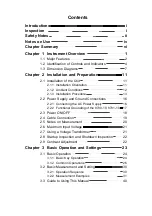
Page 3: ...er Supply and Ground Connections 16 2 2 1 Connecting the AC Power Supply 16 2 2 2 Functional Grounding of the 8730 10 8731 10 17 2 3 Power ON OFF 18 2 4 Cable Connection 19 2 5 Notes on Measurement 20 2 6 Maximum Input Voltage 21 2 7 Using a Voltage Transformer 21 2 8 Startup Inspection and Shutdown Inspection 22 2 9 Contrast Adjustment 22 Chapter 3 Basic Operation and Settings 23 3 1 Basic Operat...

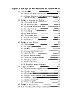
Page 4: ...per 57 4 2 9 Auto Save 58 4 3 Details of Input Setting 62 4 3 1 Range 62 4 3 2 Coupling 63 4 3 3 Filter 63 4 3 4 Voltage Axis Magnification 64 4 3 5 Zero Position 65 4 3 6 Color of Wave Display 67 4 3 7 Graph of Waveform Display 67 4 3 8 Scaling Function 68 4 3 9 Variable Function 73 4 3 10 Entering Channel Comments 75 4 4 Trigger Functions 76 4 4 1 Overview of the Trigger Functions 76 4 4 2 Trigg...

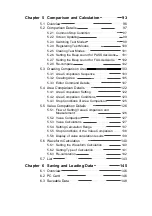
Page 5: ...ls 107 5 4 Area Comparison Details 122 5 4 1 Area Comparison Setting 122 5 4 2 Area Comparison Conditions 123 5 4 3 Stop Conditions of Area Comparison 125 5 5 Value Comparison Details 126 5 5 1 Flow of Setting Value Comparison and Measurement 126 5 5 2 Value Comparison 127 5 5 3 Value Calculations 127 5 5 4 Setting Calculation Range 137 5 5 5 Stop Conditions of the Value Comparison 138 5 5 6 Displ...

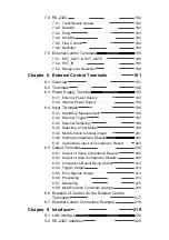
Page 6: ... 10 Deleting all files 158 6 4 11 File Details 159 Chapter 7 Adjustment and Setting of the Unit 163 7 1 Overview 165 7 2 Setting Check 166 7 2 1 Zero Adjustment 166 7 2 2 Clock setting 167 7 2 3 Language 168 7 2 4 Beep Sound 168 7 2 5 Start Backup 169 7 2 6 Contrast 170 7 2 7 Back Light Saver 171 7 2 8 System Reset 172 7 2 9 ROM RAM Check 172 7 2 10 Key Check 173 7 2 11 Display Check 173 7 3 LAN 1...

Page 7: ... 8 4 2 External Trigger 197 8 4 3 External Sampling 198 8 4 4 Selecting a Test Mode 199 8 4 5 Multi function terminal Input 201 8 4 6 Holding Comparison Results 202 8 4 7 Canceling Output of Comparison Result 203 8 5 Output Terminals 204 8 5 1 Output of Value Comparison Results 205 8 5 2 Output of Area Comparison Results 208 8 5 3 Comparison Result Being Output 212 8 5 4 Trigger Output 213 8 5 5 E...

Page 8: ...nals 235 11 1 6 External Interface 235 11 2 Input Unit Specifications 236 11 3 Trigger Unit 237 11 4 Memory Recorder Function 238 11 5 Comparison Function 239 11 5 1 Waveform Area Comparison 239 11 5 2 Value Comparison 239 11 6 Auxiliary Functions 240 11 7 Others 240 Chapter 12 Maintenance and Service 241 12 1 Maintenance and Inspection 241 12 2 Removing the Battery Before Discarding the Unit 242 ...

Page 9: ...0 13 3 3 Waveform Data MEM 250 13 3 4 Other Data 251 13 4 Glossary 252 13 5 Waveform Viewer Wv 253 13 5 1 Starting the Waveform Viewer 254 13 5 2 Waveform Viewer Menus 255 13 5 3 Using the Waveform Viewer 257 13 5 4 Conversion to CSV Format 260 13 5 5 Batch Conversion 261 Index INDEX 1 ...

Page 10: ......

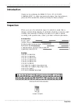
Page 11: ...en you receive the instrument inspect it carefully to ensure that no damage occurred during shipping In particular check the accessories panel switches and connectors If damage is evident or if it fails to operate according to the specifications contact your dealer or Hioki representative Accessories Power cord 1 Jumper connector 1 External control terminals label 1 Instruction manual 1 Communicat...

Page 12: ... CAUTION Indicates that incorrect operation presents a possibility of injury to the user or damage to the instrument NOTE Advisory items related to performance or correct operation of the instrument Safety Notes The symbol printed on the instrument indicates that the user should refer to a corresponding topic in the manual marked with the symbol before using the relevant function In the manual the...

Page 13: ...rotection device distribution panel Measurement categories Overvoltage categories This instrument complies with CAT I safety requirements To ensure safe operation of measurement instruments IEC 61010 establishes safety standards for various electrical environments categorized as CAT I to CAT IV and called measurement categories These are defined as follows Higher numbered categories correspond to ...

Page 14: ... insulation on the power cord is undamaged and that no bare conductors are improperly exposed Using the instrument under such conditions could result in electrocution Replace the power cord specified by Hioki Input Output Terminals Maximum Input Voltage Maximum raged voltage to earth CH1 CH2 Input Terminals 30 V rms or 60 V DC 30 V rms or 60 V DC External Control Terminals 30 V DC 30 V rms or 60 V...

Page 15: ... or scratch the printing Never touch the recorded side of the disc Do not place the disc directly on anything hard Do not wet the disc with volatile alcohol or water as there is a possibility of the label printing disappearing To write on the disc label surface use a spirit based felt pen Do not use a ball point pen or hard tipped pen because there is a danger of scratching the surface and corrupt...

Page 16: ...xplains the settings for comparison and calculation Also explains how to create a comparison area Chapter 6 Saving and Loading Data Explains how to store recall and delete measurement data and measurement settings Chapter 7 Adjustment and Setting of the Unit Explains how to adjust and diagnose the 8730 10 8731 10 and set up the interface and external control terminals Chapter 8 External Control Te...

Page 17: ...____________________________________________________________________ ______________________________________________________________________________________________ 1 2 3 4 5 6 7 8 9 10 11 12 13 14 A Chapter 1 Instrument Overview ...

Page 18: ...shelf The handles and rubber feet are easily secured with screws and can be easily removed The 8730 10 8731 10 can be assembled on a rack compliant with JIS or EIA standard or a panel A custom made mounting bracket is optionally available Please contact your vendor or our agent for details 3 High Speed Sampling The 8730 10 records the waveform of one channel and the 8731 10 records the waveforms o...

Page 19: ... and RS 232C interfaces The 9333 LAN COMMUNICATOR enables data transfers and remote control 8 External Control Terminals The external control terminals are used to output comparison results PASS or FAIL and to control the 8730 10 8731 10 The external control terminals are insulated from the power supply and GND of the 8730 10 8731 10 Value comparison and area comparison results are output from dif...

Page 20: ...FILE Key Displays the file screen This screen lets you save data on or read data from the PC card It is also used for file related operations 5 WAVE SCROLL Key Used to scroll back and forth across the waveform 6 CURSOR SCROLL Key Used to move cursors A and B 7 ADJUST SYSTEM Key Sets up the zero adjustment and clock and checks the 8730 10 8731 10 Sets up the external control terminals LAN and RS 23...

Page 21: ...CH1 waveform 2 CH2 Input Terminal Inputs the CH2 waveform 3 LAN Connector Connects the 8730 10 8731 10 to a LAN 4 RS 232C Connector Allows remote control using the RS 232C 5 External Control Terminals Used to output comparison results and control the 8730 10 8731 10 The terminal block cover includes the terminal nameplates 6 AC Connector The supplied power cord must be plugged in here 7 AC Power S...

Page 22: ..._______________________________________________________________________________________ Upper Panel 2 1 Bottom Panel Right Side Panel 3 4 Left Side Panel 3 1 Handle Serves for transporting the 2 L shaped bracket Front rubber feet with a stand are attached 3 Ventilation slots Heat is discharged from this opening Never block this opening 4 Rubber Foot ...

Page 23: ..._________________________________________________ 1 3 Dimension Diagrams ______________________________________________________________________________________________ 288 144 190 20 20 2 21 9 22 1 0 0 mm 1 3 Dimension Diagrams Main Unit Dimensions ...

Page 24: ...nsion Diagrams ______________________________________________________________________________________________ 360 27 4 φ4 5 19 4 150 131 4 R3 100 6 6 100 131 150 2 7 480 460 282 3 2 3 2 19 4 27 4 φ4 5 8 R3 55 100 131 177 138 101 6 7 1 482 6 462 7 282 7 1 JIS Rack Mounting Bracket EIA Rack Mounting Bracket ...

Page 25: ...____________________________ 1 3 Dimension Diagrams ______________________________________________________________________________________________ 282 1 3 0 138 0 1 118 118 2 φ4 5 2 φ4 5 2 M4 tap 11 6 4 5 3 2 1 8 11 6 4 5 130 100 Panel Dimensions Panel Mounting Bracket ...

Page 26: ...__________________________________________________________________________________________ 1 3 Dimension Diagrams ______________________________________________________________________________________________ ...

Page 27: ..._____________________________________________________________________________________________ 1 2 3 4 5 6 7 8 9 10 11 12 13 14 A 2 1 1 Installation Orientation Chapter 2 Installation and Preparation 2 1 Installation of the Unit Install the unit on a flat level surface The unit can also be propped up at an angle using the stand ...

Page 28: ... that generate harmful gasses e g organic silicones cyanides and formalins Subject to vibrations 1 Temperature 5 to 40o C 23 5o C recommended for high precision measurements 2 Humidity 30 to 85 RH no condensation 50 10 RH no condensation recommended for high precision measurements 3 Ventilation Take care not to block the ventilation openings and assure proper ventilation When using the unit in an ...

Page 29: ... 8731 10 or other specified screws Handle L shaped bracket L shaped bracket Rubber Foot M4X6 M4X6 M4X6 M4X6 M4X10 M4X10 M3x6 M3X6 M4X6 M4X6 M4X6 M4X6 Remove the handle and rubber feet to mount the 8730 10 8731 10 on a rack or panel 1 Remove the L shaped brackets handle and rubber feet on the sides of the 8730 10 8731 10 2 Secure the mounting bracket into the screw holes previously used to fasten t...

Page 30: ...__________________________________________________________________________ M4X6 M4x6 M4X50 M4X50 M4X6 M4X6 M4X50 M4X50 JIS Rack Mounting Bracket EIA Rack Mounting Bracket Panel Mounting For the dimensions of panel mounting brackets see 1 3 We can provide made to order panel mounting brackets Contact your dealer or Hioki representative for details ...

Page 31: ..._______________________________ 1 2 3 4 5 6 7 8 9 10 11 12 13 14 A L shaped bracket The L shaped brackets with the rubber feet may be used as simplified mounting brackets 1 Remove the L shaped brackets on the side of the 8730 10 8731 10 2 Remove the rubber feet from the L shaped brackets and exchange the right and left brackets 3 Use the M3 screws to secure the L shaped brackets in place ...

Page 32: ...risk of electric shock and damage to the unit do not use devices that have a voltage frequency outside the specified range or that output square waves 1 Voltage 100 V to 240 V AC 2 Power frequency 50 60 Hz 3 Sine wave output Do not use devices that have an unstable output even if the output is sinusoidal The 8730 10 8731 10 has no protective ground terminal but is intended to be connected to a gro...

Page 33: ...d Connections ______________________________________________________________________________________________ 2 2 2 Functional Grounding of the 8730 10 8731 10 Functional grounding terminal When the 8730 10 8731 10 is used in noise prone environments connect the functional grounding terminal to improve noise characteristics ...

Page 34: ...nto account and rated supply frequency 50 60 Hz The Unit is correctly installed Section 2 1 Power cord is correctly connected The unit is properly grounded Section 2 2 NOTE To ensure accurate measurement after powering on allow 30 minutes for temperatures within the 8730 10 8731 10 to stabilize Then perform zero adjustment and start measurement For details see 11 2 Zero adjustment see Section 7 2 ...

Page 35: ... CH2 Terminal Stand M3 5 Screw External Control Terminals Stand M3 Screw max 8 mm max 8 mm max 6 mm max 6 mm CH1 CH2 8731 10 only External Control Terminals 2 4 Cable Connection M3 5 screws are used for the CH1 and CH2 terminal blocks for the 8731 10 only M3 screws are used for the external control terminal blocks Cables are not supplied We can provide made to order cable Contact your dealer or Hi...

Page 36: ...ese ratings Power cord Connection Before using the product make sure that the insulation on the power cord is undamaged and that no bare conductors are improperly exposed Using the product under such conditions could result in electrocution Replace the power cord specified by Hioki Input Output Terminals Maximum Input Voltage Maximum raged voltage to earth CH1 CH2 Input Terminals 30 V rms or 60 V ...

Page 37: ...0 8731 10 8730 10 8731 10 GND terminal H L Voltage transformer PT Voltage transformer PT ground terminal Ground GND terminal Input Ground Input When the voltage transformer has no ground terminal When the voltage transformer has a ground terminal H L 8730 10 8731 10 Voltage transformer PT 2 6 Maximum Input Voltage 2 7 Using a Voltage Transformer CH1 CH2 When making measurements on an AC power line...

Page 38: ... that there are no abnormalities Contact your dealer Hioki representative if you find any abnormalities in appearance or function Checking Comparison Action Measure a non defective sample and a defective sample to check for correct comparison Checking 8730 10 8731 10 Performance Use three functions below to check the performance of the 8730 10 8731 10 Use these functions to check for problems ROM ...

Page 39: ...________________________________________________________________ ______________________________________________________________________________________________ 1 2 3 4 5 6 7 8 9 10 11 12 13 14 A Chapter 3 Basic Operation and Settings ...

Page 40: ... comparison area 4 FILE Key Chapter 6 Displays the file screen This screen lets you save data to or read data from a PC card 5 WAVE SCROLL Key Chapter 10 Used to scroll back and forth across the waveform 6 CURSOR SCROLL Key Chapter 10 Used to move or select cursors A and B 7 ADJUST SYSTEM Key Chapter 7 Displays the adjustment screen Performs various adjustments and self checks 8 11 CURSOR Key Chap...

Page 41: ... Menu Appears when the tag is selected Sub Menu Appears when a menu option is selected Key Lock Icon Appears when the keys are locked PC Card Icon Appears when a PC card is inserted The icon is shown in red when the auto save function is enabled LAN Icon Appears when the 8730 10 8731 10 is connected to a LAN Clock Shows the current time Cursor Indicates that an item is selected with the cursor Wav...

Page 42: ...___________________________ 3 1 2 Common Operations Display Key Display Key 4 2 5 3 2 5 2 6 4 Display Key Display Key 10 2 7 10 1 This section explains key operations common to all screens 1 Selecting Menu Options The 8730 10 8731 10 has seven keys as shown below for setting parameters working with files and performing initial settings Press a key to retrieve the corresponding screen ...

Page 43: ... format This operation is not available during measurement File name is CPhhmmss BMP hhmmss are the six digits of the hour minute and second when the file is saved 5 System Reset To reset the 8730 10 8731 10 in case of problems turn off the power then turn it on again while holding down the STOP key This will reset all settings except those for communications LAN and RS232C test mode MODE01 to 16 ...

Page 44: ...o the menu then press ENTER key to move the input cursor or make corrections For the function of each menu command see the table 3 1 2 1 Command function below The range of characters available for entering a filename or editing LAN settings is limited The screen may differ form the example shown on the left How to enter characters 1 Press the CURSOR key to move the selector cursor to the characte...

Page 45: ...does not have a half size special character font 2 2 3 3 C ε e μ u Ω o Words may be entered from List registered in the 8730 10 8731 10 1 Select List on the menu then press the ENTER key A list of registered words will appear 2 Select a word then press the ENTER key The selected word is entered Characters may be entered from History registered in the 8730 10 8731 10 1 Select History on the menu th...

Page 46: ... data 2 Comparison Setting MENU Key Setting Item Tag Detail COMP SETTINGS Comparison Area Value Calc List Sets the various parameters for waveform comparison 3 Creating Area MENU Key Setting Items Tag Detail AREA EDIT LOAD DRAWING EXTEND PAINT COMPRESS ERASER CLEAR AREA DEL REVERSE SAVE BOX set BOX reset EXIT Create the comparison area 4 Loading waveform data Panel Key Setting Items Tag Detail STA...

Page 47: ...FF Info Left Gauge CH1 Info Upper OFF Auto Save OFF Unit CH1 Range 500 mV Coupling DC Filter 5kHz Zoom X1 ZeroPos 50 Wave Red Scaling OFF Variable OFF Trigger Trigger Mode Repeat Pre Trigger 0 Trigger Source OR CH1 Level 0 V UP CH2 OFF External OFF Timer OFF Example 1 Connect an oscillator to the 8730 10 8731 10 and measure 4 Vp p 1 kHz sine waves 1 Connect an oscillator to the 8730 10 8731 10 2 S...

Page 48: ...ove the key will go on In this example the 8730 10 8731 10 has already received input and the trigger is activated immediately Since the trigger is set to Repeat measurement will not stop automatically even if the recording length of data has been exceeded 7 Stop measurement Press the STOP key The LED above the key will go out Measurement is interrupted 8 Saves the screen as a bitmap file Hold dow...

Page 49: ... steps 1 to 5 of Example 1 2 Load a waveform Press the AREA EDIT key to display the Editor screen Select LOAD and set CH1 as the load source to load the CH1 waveform Set the mode to LastWave Press the START key to start loading 3 Extend the loaded waveform data and create a comparison area Use the CURSOR key to set the extension width then press the START key 4 Save the comparison area Select the ...

Page 50: ...Area or Value Area CH1 Comparison ON FAIL Mode OUT Using Area A01 Stop Mode FAIL The comparison result is PASS with the waveform shown against a green background The comparison result is FAIL the waveform shown against a red background 5 Exit the Editor screen Select EXIT to end area edit 6 Set the area comparison parameters Press the COMP SETTINGS key 7 Press the START key to start area compariso...

Page 51: ...r Value Value Measurement ON No 1 Average Comparison OFF No 2 RMS Comparison OFF No 3 Frequency Comparison ON Upper 1 01 k Lower 980 No 4 Period Comparison OFF Measure Range All Wave Stop Mode FAIL Example 3 Compare the value 1 Set the parameters via steps 1 to 5 of Example 1 except for setting the Info left to CompResult in the step 3 measurement setting of Example 1 2 Set the value comparison pa...

Page 52: ...o Left Gauge CH1 Info Upper OFF Auto Save OFF Unit CH1 Range 1 V Coupling DC Filter OFF Zoom X1 ZeroPos 50 Wave Red Graph Not selectable Scaling OFF Variable OFF Comment Blank Trigger Trigger Mode Repeat Pre Trigger 15 Trigger Source OR CH1 Level Level 0 V UP Filter OFF External OFF Timer OFF Example 4 Detect overshoot and undershoot 1 Connect the output terminal to be measured to the input termin...

Page 53: ...mV 0 50DIV 100 μs 0 50DIV 100 μs 5 Load the waveform data and create an area Press the START key to load the waveform data Press the AREA EDIT key and execute the LOAD command Set the load source to CH1 and the mode to LastWave 6 Extend the comparison area Use the EXTEND command to set the width then press the START key 7 Save the created area to internal memory Select the SAVE command to save the...

Page 54: ...Area or Value Refresh Disp Always Select Mode Do not set Register Mode Do not set Re compare Disabled by default Area Comparison ON CH1 FAIL Mode OUT CH1 Using Area A07 Stop Mode FAIL 8 Exit the Editor screen Select EXIT and press the ENTER key 9 Set the comparison parameters Press the COMP SETTINGS key 10 Set the area comparison parameters Select the Area tag and set the parameters as shown below...

Page 55: ... from the comparison area FAIL The measured waveform deviates from the comparison area 11 Press the START key to start measurement After loading the waveform a comparison begins As shown below if a waveform has an overshoot or an undershoot left figure the measured waveform deviates from the comparison area and will be compared as FAIL If the duty ratio of the pulse is disturbed in the right figur...

Page 56: ...____________________________________________________________________________________________ Section Title Section summary Tag and setting parameters on the menu Key Setting Screen Explanations of related issues Operating procedure Notes and remarks 3 3 Guide to Using This Manual This instruction manual is organized as shown below ...

Page 57: ..._____________________________________________________________ ______________________________________________________________________________________________ 1 2 3 4 5 6 7 8 9 10 11 12 13 14 A Chapter 4 Settings on the Measurement Screen ...

Page 58: ...rbitrary recording length Time Zoom See 4 2 3 X 1 100 to X 10 Format See 4 2 4 Single Dual XY Average See 4 2 5 OFF 2 to 16 times Overlay See 4 2 6 OFF ON Info Left See 4 2 7 OFF Gauge CH1 Gauge CH2 CompResult Measure Info Upper See 4 2 8 OFF Comment Setting Auto Save See 4 2 9 Wave Data OFF PC CARD LAN Save Type Binary Text Thin out text OFF 1 2 to 1 100 Wave BMP OFF PC CARD LAN Save Type Noncomp...

Page 59: ... 14 A Unit See 4 3 CH1 Range See 4 3 1 100 mV to 5 V Coupling See 4 3 2 DC GND Filter See 4 3 3 OFF 5 Hz to 100 kHz Zoom See 4 3 4 X1 2 to X10 ZeroPos See 4 3 5 950 to 1050 max Wave See 4 3 6 OFF RED GREEN BLUE CYAN Graph See 4 3 7 Graph1 Graph2 Scaling See 4 3 8 Setting OFF ON Ratio Setting EU OFFSET Point Setting Input1 Scale1 Input2 Scale2 Unit Variable See 4 3 9 OFF ON Upper Lower Comment See ...

Page 60: ...e Trigger See 4 4 3 0 to 100 Trigger Source See 4 4 4 OR AND CH1 See 4 4 5 OFF Level Level 50 V to 55 V Slope UP DOWN Filter OFF 0 1 DIV to 10 DIV In Upper 55 V max Lower 50 V min Filter OFF 0 1 DIV to 10 DIV Out Upper 55 V max Lower 50 V min Filter OFF 0 1 DIV to 10 DIV Period Level 50 V to 55 V Slope UP DOWN Upper 1000 min max Lower 10 ms min CH2 See 4 4 5 Same as CH1 External See 4 4 6 OFF ON T...

Page 61: ...s the data for two input channels on the same time axis for the 8731 10 only The waveforms of both channels are superimposed This helps clarify the correlation between input signals 3 Time axis setting 100 μs DIV to 5 min DIV 4 Time axis resolution 100 points DIV 5 Storage capacity Up to 500 DIV 6 Displayed waveforms can be magnified or compressed Time axis direction x10 to x1 100 Voltage axis dir...

Page 62: ...ime axis setting 3 Voltage axis range setting Select a suitable voltage axis range for the voltage to be measured Failure to set an appropriate voltage axis range may result in inaccurate measurement For example the waveform may exceed the range or a large measurement error may occur 4 Trigger setting Select Single to record only the set data length Select Repeat to accept the trigger repeatedly W...

Page 63: ...s range 100 samples DIV Selecting external sampling will synchronize sampling with the external signal 1 kHz or less Setting Procedure 1 Press the DISPLAY key to select the Configure tag Press the ENTER key to display the menu 2 Move the cursor to Time DIV and press the ENTER key 3 Use the CURSOR key to select a value then press the ENTER key to set the time axis value The currently selected time ...

Page 64: ...0 or 500 2 Arbitrary recording length mode Set an arbitrary number for recording length Setting Procedure 1 Constant recording length mode 1 Press the DISPLAY key to select the Configure tag Press the ENTER key to display the menu 2 Move the cursor to Shot and press the ENTER key 3 Use the CURSOR key to select a value then press the ENTER key to set the recording length value The currently selecte...

Page 65: ...ecording Length Increases in number Moves the cursor to the right Decreases in number Moves the cursor to the left Confirms the value NOTE In arbitrary recording length mode the selectable range is from 1 DIV to 500 DIV Note 1 When the time axis range is set to External the recording length is expressed as the number of samples The selectable range is 100 to 50 000 samples The number of samples to...

Page 66: ... X10 NOTE Edits the magnification compression rate of the time axis The time axis may be magnified to show the waveform in detail or compressed to show overall changes The image is magnified or compressed with the left edge as the datum line Setting Procedure 1 Press the DISPLAY key to select the Configure tag Press the ENTER key to display the menu 2 Move the cursor to Time Zoom and press the ENT...

Page 67: ...lotted on the X axis CH2 is plotted on the Y axis X Y Y X Single screen display NOTE Graph 2 Graph 1 Dual screen display XY screen display Sets the display format to display a waveform The display formats include single screen dual screen and XY screen for the 8731 10 only Setting Procedure 1 Press the DISPLAY key to select the Configure tag Press the ENTER key to display the menu c 2 Move the cur...

Page 68: ... the trigger is not set properly the intended result may not be obtained See 4 4 For the calculation equations for averaging see 13 2 4 When averaging is enabled waveform calculation see 5 6 is disabled The averaging function allows capturing several instances of a waveform and determining the average This makes it possible to eliminate noise and irregular signal components Setting Procedure 1 Pre...

Page 69: ...en the trigger mode is set to Auto data is loaded after a certain time even if the trigger conditions are not met This results in meaningless data from averaging an unsynchronized signal Start measurement Wait for trigger Store the waveform for set data recording length Averaging additive average Area comparison Value comparison Note 1 Save data on the PC card Note 2 End measurement Clear the wave...

Page 70: ...gger mode is Repeat or Auto This allows comparison to the immediately preceding waveform Setting Procedure 1 Press the DISPLAY key to select the Configure tag Press the ENTER key to display the menu 2 Move the cursor to Overlay and press the ENTER key 3 Select ON or OFF then press the ENTER key to confirm the overlay function setting When the trigger mode is set to Single overlay is not available ...

Page 71: ...he Configure tag Press the ENTER key to display the menu 2 Move the cursor to Info Left and press the ENTER key 3 Use the CURSOR key to select an item then press the ENTER key OFF Does not display any information Gauge CH1 Displays the gauge of CH1 Note 1 Gauge CH2 Displays the gauge of CH2 Note 2 CompResult Displays the Waveform comparison result PASS FAIL Measure Displays the comparison result a...

Page 72: ...son result Area comparison result Value comparison result No 1 to 4 This will not appear when area comparison is disabled This will not appear when value comparison is disabled CH1 CH2 When the Measure is selected FAIL C H 1 PASS C H 2 FAIL 1 PASS 5 0000 5 0000 2 FAIL 1 0000 1 0000 3 PASS 2 0000k 1 5000k 4 FAIL 500 00m 0 0000 Total comparison result CH1 Area comparison result CH2 Area comparison r...

Page 73: ...ment OFF Scroll Bar File Comment Comment of CH1 Comment of CH2 Setting Setting of CH1 Setting of CH2 Count PASS count TEST count Count File Comment Count File Comment FAIL count Count Channel Comment Comment of CH1 Comment of CH2 Count NOTE Comments will not appear without inputting it in advance A file comment will apear when loading a file or switching test modes In case of no comparison only th...

Page 74: ... key to display the menu 2 Move the cursor to Auto Save and press the ENTER key 3 Use the CURSOR key to select the setting item then press the ENTER key to confirm each item The file is saved in the currently selected directory on the file screen A limited number of directories or files can be saved in a directory Data exceeding a certain size may not be saved to a PC card For details see 6 4 11 1...

Page 75: ...8731 10 When Wave Data is set to OFF the save format cannot be selected For an example of saving in text CSV format see 4 of 6 4 11 When LAN is set as the saving destination data is saved in TXT format files named WAVEhhmmss TXT where hhmmss are the six digits of the hour minute and second when the file is saved When waveform calculation is enabled only calculated waveforms are saved 3 Setting the...

Page 76: ...ata to a PC card LAN Saves BMP data on a LAN connected PC Requires use of the 9333 LAN COMMUNICATOR During comparison the data is saved when the stop conditions are met 5 Setting the Save Format of BMP Screen Data Non compressed Compressed The BMP screen data is saved in either compressed or non compressed format This selection is available when Wave BMP is set to PC CARD or LAN When saved in comp...

Page 77: ...ires use of the 9333 LAN COMMUNICATOR When comparison is enabled the data is saved when the stop conditions are met For examples of saving calculation results see 5 in 6 4 11 Calculation results are successively saved in one file The file name is MEASURE CSV When LAN is set as the saving destination for selected text data is saved in TXT format files named PARAMETER TXT A new file is created whene...

Page 78: ...tage axis direction After the range has been changed perform zero adjustment see 7 2 1 Setting Procedure 1 Press the DISPLAY key and use the right and left CURSOR keys to select the Unit tag 2 Select the channel to set then press the ENTER key Note 1 3 Select Range then press the ENTER key 4 Select a value then press the ENTER key Note 1 Channel selection is not possible with the 8730 10 Select a ...

Page 79: ...ote 1 3 Select Coupling then press the ENTER key 4 Select DC or GND then press the ENTER key DC Performs DC coupling GND The input signal is not connected This is used to check the zero position Note 1 Channel selection is not possible with the 8730 10 The currently selected setting is shown in red Sets a low pass filter for input signals This is effective in removing unwanted harmonic components ...

Page 80: ...creen as a datum point Setting Procedure 1 Press the DISPLAY key and use the right and left CURSOR keys to select the Unit tag 2 Select the channel to set then press the ENTER key Note 1 3 Select Zoom then press the ENTER key Note 2 4 Select a ratio then press the ENTER key Note 1 Channel selection is not possible with the 8730 10 Note 2 Zoom cannot be selected when the variable function is ON See...

Page 81: ...e percentage of screen height where 0V is to be positioned The bottom of the graph is 0 the top is 100 Setting Procedure 1 Press the DISPLAY key and use the right and left CURSOR keys to select the Unit tag 2 Select the channel to set then press the ENTER key Note 1 3 Select ZeroPos on the menu then press the ENTER key Note 2 4 Select a value then press the ENTER key Note 1 Channel selection is no...

Page 82: ...etween 10 times to 11 times the set voltage axis range If input exceeds the measurable range a range over occurs and the waveform is shown in black If a range over occurs a warning message appears and the ERROR terminal of the external control terminals becomes active You can enable or disable this function See 7 5 3 for details Changing the zero position or the magnification or compression rate o...

Page 83: ...OFF or a color then press the ENTER key Note 1 Channel selection is not possible with the 8730 10 The currently selected wave display color is shown in red When OFF is selected the waveform is not displayed The comparison area or calculation result is not displayed either but comparison is performed This saves time for display processing and thus slightly reduces the comparison period Selects a gr...

Page 84: ...will cause the measurement voltage to be converted into the selected units Setting Screen Unit CH1 CH2 Scaling Setting Ratio Setting Point Setting Unit NOTE The scaling function can be used to convert an output voltage from a sensor or similar into a physical quantity Two types of scaling functions are available The gauge scale and A B cursor measurement values are displayed in the scaled units Sc...

Page 85: ...tion of each key is shown in the figure below The input field is nine digits long excluding the decimal point as shown in the figure below Digits A and B are used for signs and prefixes The five most significant digits of numbers are effective A Displays a blank or A blank indicates a positive value the indicates a negative value B Displays a blank or SI prefix For details of SI prefix see 13 2 5 ...

Page 86: ...caling in Ratio Setting EU OFFSET Scaling is performed by specifying a physical quantity to correspond to a 1 V input signal conversion ratio EU V an offset value and the unit EU Engineering Units This will cause the measurement voltage to be converted into the selected units Setting Procedure 1 Select Ratio Setting on the Scaling menu then press the ENTER key 2 Enter a value for EU 3 Enter a valu...

Page 87: ...ineering units EU This will cause the measurement voltage to be converted into the selected units Setting Procedure 1 Select Point Setting on the Scaling menu then press the ENTER key 2 Enter a value for Input1 3 Enter a value for Scale1 4 Enter a value for Input2 5 Enter a value for Scale2 The value at the cursor position if between 0 0001 and below 100000 is not expressed as an exponent but is s...

Page 88: ... below Any attempt to set an upper or lower limit outside the range will display a warning message 9 9999E 19 Set value 1 0000E 19 Set value 0 1 0000E 19 Set value 9 9999E 19 4 Setting the Unit Input the unit EU used for a scaled value Setting Procedure 1 Select Unit on the Scaling menu then press the ENTER key 2 The screen for entering characters will appear so you can enter a unit For how to ent...

Page 89: ...ach channel individually Note 1 Waveform calculation turns on the variable function see 5 6 Setting Procedure 1 Press the DISPLAY key and use the right and left CURSOR keys to select the Unit tag 2 Select the channel to set then press the ENTER key Note 1 3 Select Variable on the display menu then press the ENTER key 4 Use the CURSOR key and ENTER key to select ON then set the upper and lower limi...

Page 90: ...key is shown in the figure below The input field is nine digits long excluding the decimal point as shown in the figure below Digits A and B are used for signs and prefixes The five most significant digits of numbers are effective A Displays a blank or A blank indicates a positive value the indicates a negative value B Displays a blank or SI prefix For details of the SI prefix see 13 2 5 Related I...

Page 91: ...NOTE Allows you to enter a comment for each channel The comment is displayed when Comment is selected for the Info Upper setting Setting Procedure 1 Press the DISPLAY key and use the right and left CURSOR keys to select the Unit tag 2 Select the channel to set then press the ENTER key Note 1 3 Select Comment then press the ENTER key 4 Enter a comment For how to enter comments see 8 in 3 1 2 Note 1...

Page 92: ...ng the Pre trigger Records the waveform before a trigger in addition to the waveform after a trigger NOTE When all trigger sources are OFF the 8730 10 8731 10 loads the waveform as soon as it starts measurement free run operation During recording operation Wait for trig appears on the screen until the trigger sources are met 4 4 Trigger Functions The term Trigger refers to a signal which is used t...

Page 93: ...ey and use the right and left CURSOR keys to select the Trigger tag 2 Select Trigger Mode then press the ENTER key Note 1 3 Select an item then press the ENTER key Single Trigger is registered only once 8730 8730 10 starts waveform recording when triggering occurs and continues for preset recording length Measurement then ends automatically Repeat Trigger is registered continuously Unit is in trig...

Page 94: ... Decreases in number Editing Pre trigger Moves the cursor to the left Confirms the value NOTE The pre trigger function serves to record the waveform not only after but also before triggering has occurred When recording a waveform using the recording start point as 0 and the recording end point as 100 the trigger point can be specified in percent Setting Procedure 1 Press the DISPLAY key and use th...

Page 95: ... Note external trigger and timer trigger may be combined to activate a trigger using AND OR logic Note Only CH1 is available with the 8730 10 Setting Procedure 1 Press the DISPLAY key and use the right and left CURSOR keys to select the Trigger tag 2 Select Trigger Source on the display menu then press the ENTER key 3 Select an item then press the ENTER key OR Activates a trigger when any trigger ...

Page 96: ... use the right and left CURSOR keys to select the Trigger tag 2 Select CH1 or CH2 on the display menu then press the ENTER key 3 Using the CURSOR key to select an item to set then press the ENTER key The currently selected trigger source is shown in red When the trigger sources are OFF a trigger will not be activated 1 Level Trigger Level Slope Filter Using the trigger level voltage triggering occ...

Page 97: ...Trigger Level Move the cursor to left Confirms the value Range Setting range Step 100 mV 1 V to 1 1 V 0 0025 V 200 mV 2 V to 2 2 V 0 005 V 500 mV 5 V to 5 5 V 0 0125 V 1 V 10 V to 11 V 0 025 V 2 V 20 V to 22 V 0 05 V 5 V 50 V to 55 V 0 125 V Example The trigger slope is set to UP and the trigger filter is used Setting the Level Trigger 1 On the trigger condition menu of a channel CH1 or CH2 select...

Page 98: ...Trigger Slope DOWN Setting the Trigger Slope 3 Set the slope condition under Slope as follows UP Activates a trigger at the rise of a waveform DOWN Activates a trigger at the fall of a waveform Examples for Setting To activate a trigger at points A and B of a sine wave as shown in the figure below set the conditions as follows Setting the Trigger Filter 4 Set the trigger filter under Filter OFF Do...

Page 99: ... 2 V A B A B 2 V 0 005 V 500 mV 5 5 V A B A B 5 V 0 0125 V 1 V 11 V A B A B 10 V 0 025 V 2 V 22 V A B A B 20 V 0 05 V 5 V 55 V A B A B 50 V 0 125 V 2 Window in out Trigger Upper limit Lower limit Filter When using the window in out trigger a trigger is activated when the waveform enters or exits the range between the upper and lower limits of the trigger level Using the trigger filter prevents an ...

Page 100: ...____________________ 1V 1V T Window out Trigger Upper limit 1 V Lower limit 1 V Setting the Trigger Filter 4 Next move to the Filter setting OFF Does not use a trigger filter 0 1 to 10 0 DIV Uses a trigger filter with the width of the set number of DIV Setting Example To activate a trigger when a waveform as shown in the figure below deviates from the shaded area set the conditions as follows ...

Page 101: ...limit example Signal period Reference voltage 0 V Signal period Lower limit example 基準電圧 0V 1 00s 1 05s 1 1s 1 2s T 周期範囲内 周期範囲内 周期上限 周期範囲外 0 95s 周期下限 Reference voltage 0 V Lower limit period 0 95 s Upper limit period 1 1 s Within the period range Outside the period range 1 00 s 1 05 s 1 2 s Lower limit 950 ms Upper limit 1 1 s Level 0 000 V NOTE A trigger may be activated by a period shorter than ...

Page 102: ...ms 600 ms 1 2 s 3 s Maximum upper limit 40 s 100 s 200 s 400 s 1000 s 2000 s 100 min 200 min 400 min 1000 min Minimum lower limit 20 ms 50 ms 100 ms 200 ms 500 ms 1 s 3 s 6 s 12 s 30 s Setting the Period Trigger 1 On the trigger condition menu of a channel CH1 or CH2 select Period then press the ENTER key 2 Set a trigger level under Level 3 Set a slope condition under Slope UP Activates a trigger ...

Page 103: ...external input terminal may be used as a trigger source Use the EXT_TRIG terminal When using the EXT_TRIG terminal see 8 4 2 for details Setting Procedure 1 Press the DISPLAY key and use the right and left CURSOR keys to select the Trigger tag 2 Select External then press the ENTER key ON Uses the external trigger OFF Does not use the external trigger The timer trigger is used for preset time reco...

Page 104: ... be set to come after the time START key is pressed When the trigger mode is set to Single a trigger is activated only once at the start time The interval or stop time settings are ineffective when only the timer trigger is ON When trigger sources have been linked with OR all trigger sources are valid Therefore triggering may occur even before the start time and trigger standby and measurement may...

Page 105: ...gger Invalid overlaps with recording Start Start Recording Time Interval Start Time A trigger is activated only once within an interval Stop Time Time Level trigger Slope UP Recording Length Relation between Timer Trigger and AND OR linking a Trigger source AND OR is set to OR All trigger sources become effective If another trigger source is set a trigger may be activated before the start time or ...

Page 106: ...ter Setting of the timer trigger Start time Stop time Time interval CH1 Coupling Display Color Comment of CH1 Range Time axis magnification Range on the display Zero Position Filter Setting of the Scaling Function Unit Conversion Ratio Offset Setting of the Variable Function Upper limit Lower limit CH2 Coupling Display Color Comment of CH2 Range Time axis magnification Range on the display Zero Po...

Page 107: ...ts when a FAIL comparison result is returned Auto save is initiated only when the stop conditions are met Measurement continues until the user presses the STOP key Auto save is initiated each time regardless of the comparison result Measurement halts after a single operation regardless of comparison result Auto save is initiated regardless of comparison result PASS PASS FAIL PASS FAIL PASS PASS PA...

Page 108: ...________________________________________________________________________________ 4 6 Auto save based on comparison results ______________________________________________________________________________________________ ...

Page 109: ...5 6 7 8 9 10 11 12 13 14 A AREA EDIT Key See 5 3 LOAD See 5 3 3 1 EXTEND See 5 3 3 2 COMPRESS See 5 3 3 3 CLEAR See 5 3 3 4 REVERSE See 5 3 3 5 PAINT See 5 3 3 6 BOX set See 5 3 3 7 DRAWING See 5 3 3 8 LINE RECT RECT CIRCLE CIRCLE ERASER See 5 3 3 9 AREA DEL See 5 3 3 10 SAVE See 5 3 3 11 EXIT See 5 3 3 12 Chapter 5 Comparison and Calculation The area creation screen lets you set the commands belo...

Page 110: ...lways Select Mode See 5 2 3 MODE01 to MODE16 Register Mode See 5 2 4 MODE01 to MODE16 Erase Mode See 5 2 5 MODE01 to MODE16 PASS Beep See 5 2 6 OFF BEEP1 BEEP2 BEEP3 FAIL Beep See 5 2 7 OFF BEEP1 BEEP2 BEEP3 Re compare See 5 2 8 Area See 5 4 Comparison See 5 4 1 OFF ON CH1 See 5 4 2 FAIL Mode See 5 4 2 OFF OUT ALL OUT Using Area See 5 4 2 A01 to A16 CH2 See 5 4 2 Same as CH1 Stop Mode See 5 4 3 PA...

Page 111: ...ak Integration Maximum Difference Max Time Pulse Width Minimum DUTY Min Time Level Time Period Pulse Count Frequency MAX MIN XY Area Level CH CH1 CH2 Comparison OFF ON Upper Lower No 2 See 5 5 3 Same as No 1 No 3 See 5 5 3 Same as No 1 No 4 See 5 5 3 Same as No 1 Measure Range See 5 5 4 All Wave Part Wave Stop Mode See 5 5 5 PASS FAIL PASS FAIL Calc See 5 6 Calculation See 5 6 1 OFF ON CH1 See 5 6...

Page 112: ... is compared regardless of recording length A comparison area may be created using an acceptable waveform The 8730 10 8731 10 can store up to 16 areas in memory The areas can be also stored on a PC card Depending on the comparison results signals are output from the OK terminal or NG terminal of the external control terminals See 8 5 2 for details 2 Value Comparison See 5 5 Performs value calculat...

Page 113: ...area and value comparison The 8730 10 8731 10 may be set to stop measurement depending on the area or value comparison result PASS or FAIL In addition the data may be saved depending on whether the auto save setting has been selected See 4 2 9 for details For the area and value comparison stop conditions see 5 4 3 and 5 5 5 If comparison is disabled the system assumes that the stop conditions of t...

Page 114: ...er conditions are not met NOTE Start measurement Wait for trigger Store the waveform for set data recording length Calculation Note1 Area comparison Value comparison Note 2 Saves data automatically Note 3 Stop measurement YES Are the stop conditions met Note 2 NO Note 1 This only applies when waveform calculation is ON Note 2 This only applies when area comparison or value comparison is enabled If...

Page 115: ... FAIL The L part of output is at least 10 ms For details see 8 5 2 Setting Procedure 1 Press the COMP SETTINGS key and select Comp tag 2 Use the CURSOR key to select Refresh Disp on the menu 3 Use the CURSOR key to select a condition then press the ENTER key OFF Does not update the screen Stop Mode Updates the screen only when the comparison result satisfies the stop conditions Always Always updat...

Page 116: ...rison value comparison and measurement except for communications LAN RS 232C and contrast If test modes are registered in advance the settings can be changed using the MODE terminals of the external control terminals Comments can be entered for each test mode Setting Procedure 1 Press the COMP SETTINGS key select Comp tag then press the ENTER key 2 Select Register Mode on the display menu and pres...

Page 117: ... on the display menu and press the ENTER key 3 Use the CURSOR key to select a test mode should be cleared from MODE01 to MODE16 on the menu then press the ENTER key On the menu the saved test modes are shown in black A mode must be saved before it can be selected The beeper can be set to indicate the comparison results You can select the type of beep to sound upon PASS results This setting is effe...

Page 118: ...Beep on the display menu and press the ENTER key 3 Use the CURSOR key to select a beep sound on the menu then press the ENTER key OFF No beep sounds BEEP1 FAIL results are indicated by four short beeps BEEP2 FAIL results are indicated by one beep BEEP3 FAIL results are indicated by a long and a short beep Compares the waveform previously stored Only calculation is possible here Upon comparison the...

Page 119: ...ing on whether the waveform is within or outside the area By comparing an input waveform an abnormal waveform can be detected This section explains the general flow of operation and settings 1 Creating the Comparison Area Load Read an already created comparison area from the PC card This is done on the File screen New Use the editor commands to create a Comparison area The created areas may be sav...

Page 120: ...リアから波形が完全に外れた らNG判定 OK判定でストップ NG判定でストップ OK NG OK NGどちらの判定でもストップ ALL OUT PASS FAIL PASS FAIL Return FAIL if any part of the waveform leaves the comparison area Stop at PASS comparison Stop at FAIL comparison Stop at PASS or FAIL comparison Return FAIL if the entire waveform leaves the comparison area Stop at PASS comparison Stop at FAIL comparison Stop at PASS or FAIL comparison NOTE The A B cursor...

Page 121: ...n the area No selected in 3 above 5 Press the AREA EDIT key Use the LOAD command to load the area specified in 3 above then edit the area For details of the LOAD command see 5 3 3 You can simultaneously load all area data saved in a directory on the 8730 10 8731 10 by loading the index file For details of the index file see 6 4 6 2 Creating a New Area This section explains how to create a new comp...

Page 122: ...rdinate X coordinate Creating Area Edit Command Area Edit Display Displays X Y coordinates with the origin 0 0 placed at the upper left corner of the screen Time and voltage values are also displayed With the default setting the voltage values are calculated based on the CH1 voltage axis range When the waveform of CH2 is loaded calculation is based on the CH2 voltage axis range When scaling is ON ...

Page 123: ...the 8731 10 When CH1 or CH2 is selected as the load source choose a type from LastWave Overlay Magnify and AREA When a file is selected as the load source specify the file name Drawing Procedure 1 Use the CURSOR key to select LOAD command then press the ENTER key 2 Use the up and down CURSOR keys to set the load source CH1 Loads the waveform of CH1 CH2 Loads the waveform of CH2 for the 8731 10 onl...

Page 124: ...ryselected on the Card screen are displayed 5 Press the START key to start loading Use the up and down CURSOR keys to select a file Only those files that can be loaded from the current directory selected on the File screen are displayed The BMP image data of the area saved by the SAVE command is loaded The area can be changed on the PC but if resized or if colors are changed it cannot be reloaded ...

Page 125: ...right Use this command to create an area based on an acceptable waveform The extension width is defined by specifying the number of DIVs The time and voltage values corresponding to the number of DIVs appear under the number of DIVs The BOX set command can be used for partial area enlargement Drawing Procedure 1 Use the CURSOR key to select EXTEND command then press the ENTER key 2 Use the up and ...

Page 126: ... the screen up and down and left and right The compression width is defined by specifying the number of DIVs The time and voltage values corresponding to the number of DIVs appear under the number of DIVs The BOX set command can be used for partial area compression Drawing Procedure 1 Use the CURSOR key to select COMPRESS command then press the ENTER key 2 Use the up and down voltage axis directio...

Page 127: ... before deletion Screen image after deletion Screen image after deletion with a range specified 4 CLEAR Delete the area you are working on Deletes the entire area you are working on The BOX set command can be used for partial area deletion Drawing Procedure 1 Use the CURSOR key to select CLEAR command and press the ENTER key Then the area is deleted Executing CLEAR with a range specified only dele...

Page 128: ...____ Screen image before reversal Screen image after reversal Screen image after reversal with a range specified 5 REVERSE Reverse the area Reverse the filled in area and unfilled area The BOX set command can be used for partial area reversal Drawing Procedure 1 Use the CURSOR key to select REVERSE command then press the ENTER key Executing REVERSE with a range specified only reverse the specified...

Page 129: ...of filling in color 1 POINT mode Fills the enclosed space selected by the cross cursor 2 CLOSED mode Fills all enclosed spaces you are working on This is useful for creating an area based on overlaid waveforms The BOX set command can be used for partial area filling Drawing Procedure 1 Use the CURSOR key to select PAINT command then press the ENTER key 2 Select a filling mode The mode is set to PO...

Page 130: ...tangle box with diagonal line specified by these two points The specified range is enclosed in a red frame The lines of the rectangle are included in the range Operation Procedure 1 Use the CURSOR key to select BOX set command then press the ENTER key 2 The cursor and the coordinates X coordinate Y coordinate are displayed on the screen 3 Use the CURSOR key to move the cursor to the start point th...

Page 131: ...pecified by two points The rectangle will not be filled in 3 RECT Draws a rectangle with diagonal line specified by two points The rectangle will be filled in 4 CIRCLE Draws a circle with the radius specified by two points The circle will not be filled in 5 CIRCLE Draws a circle with the radius specified by two points The circle will be filled in Drawing Procedure 1 Use the CURSOR key to select DR...

Page 132: ...n switches modes to low speed motion dot by dot movement 8 1 LINE Draws a line Draws a line between the start and end points you specify Drawing Procedure 1 Use the CURSOR key to select DRAWING command then press the ENTER key The DRAWING command menu will then appear Select the LINE command then press the ENTER key 2 The cursor and the coordinates X coordinate Y coordinate are displayed on the sc...

Page 133: ...ws a rectangle with diagonal line specified by two points The rectangle will be filled in Drawing Procedure 1 Use the CURSOR key to select DRAWING command then press the ENTER key The DRAWING command menu then appears Select the RECTANGLE command then press the ENTER key RECT Does not fill in the rectangle RECT Automatically fills in the rectangle 2 The cursor and the X Y coordinates will appear o...

Page 134: ...nts center point and circumferential point The circle will be filled in Drawing Procedure 1 Use the CURSOR key to select DRAWING command then press the ENTER key The DRAWING command menu then appears Select the CIRCLE command then press the ENTER key CIRCLE Does not fill in the circle CIRCLE Automatically fills in the circle 2 The cursor and the X Y coordinates will appear on the screen 3 Use the ...

Page 135: ...inate 9 ERASER Delete part of the area Delete part of an area by moving the eraser mark 10 dots wide 20 dots long Procedure 1 Use the CURSOR key to select ERASER command then press the ENTER key 2 The cursor and the X Y coordinates will appear on the screen 3 Use the CURSOR key to move the cursor to a section to delete then press the ENTER key The cursor will change to 4 As the cursor moves the se...

Page 136: ...t deletion Note that selecting ALL deletes all areas in memory 11 SAVE Save the created area Save the created area A01 to A16 in internal memory or file PC card When a file is selected as the load source specify the file name A created area will not be valid unless saved in 8730 10 8731 10 internal memory Procedure 1 Use the CURSOR key to select SAVE command then press the ENTER key 2 Use the CURS...

Page 137: ...ously used to save another area will overwrite the previous area 12 EXIT Ends area creation Ends area creation and exits the Area creation screen Procedure 1 Use the CURSOR key to select EXIT command then press the ENTER key The Area creation screen is then exited and the waveform display screen appears After creating an area if you select EXIT without saving the area a warning message will appear...

Page 138: ...e separately for each channel except for the 8730 10 Area comparison enables the detection of an abnormal waveform that deviates from the set waveform range The comparison result PASS or FAIL is output from an external control terminal For details of the external control terminals see 8 5 2 Turns area comparison ON OFF Setting Procedure 1 Press the COMP SETTINGS key and select Area tag 2 Select Co...

Page 139: ...y registering comparison areas you can easily switch between different areas Up to 16 comparison areas may be registered For how to create a comparison area see 2 in 5 3 2 Setting Procedure 1 Press the COMP SETTINGS key and select Comparison tag Note 1 2 Select a channel CH1 or CH2 Note 2 then press the ENTER key 3 Use the CURSOR key to select FAIL Mode or Using Area FAIL Mode Selects a comparison...

Page 140: ...h CH1 and CH2 comparison will not be conducted The A B cursor function is available even during area comparison A range for area comparison cannot be specified When the Trigger Mode is set to Single measurement continues until the stop conditions are met and ends as soon as these conditions are met When the Trigger Mode is set to Repeat or Auto the waveform is recorded continuously and compared Me...

Page 141: ...he result is FAIL NOTE The 8730 10 8731 10 may be set to stop measurement according to the result of area comparison PASS or FAIL Enabling the auto save function saves the data see 4 2 9 When value comparison is also conducted simultaneously measurement ends according to the common stop conditions see 5 2 1 Setting Procedure 1 Press the COMP SETTINGS key and select Area tag Note 1 2 Use the CURSOR...

Page 142: ...inal For details see 8 5 1 Make setting separately for each channel except on the 8730 10 Up to four calculations No 1 to No 4 may be set Calculations are made in order from No 1 to No 4 Value calculations can also be made without comparison The results of value calculations can be saved see 4 2 9 and 6 4 11 No 5 This section describes the minimum settings and operating procedure This function mak...

Page 143: ...you do not need to set them again each time you turn this setting ON or OFF Setting Procedure 1 Press the COMP SETTINGS key and select Value tag 2 Select a value on the menu then press the ENTER key 3 Use the CURSOR key to select OFF or ON then press the ENTER key OFF Does not conduct value comparison ON Conducts value comparison Calculations without comparison can also be made The upper and lower...

Page 144: ...di Σ i 1 1 n RMS di2 n i 1 1 n Σ ピーク値 最大値 最小値 Max Min Peak 最大値 Max Listed below are the types of calculation available for value comparison 1 OFF No calculations are made 2 Average Obtains the average V of waveform data Formula AVE Averaging value n Source number of data di i th data of the channel 3 RMS Obtains the RMS V of waveform data When scaling is ON calculation is made after the waveform d...

Page 145: ...ximum value is measured at multiple points only the first measurement is used as the maximum value 7 Minimum Obtains the minimum value V for waveform data 8 Min Time Obtains the time at which the minimum value is measured and obtains the difference time s between that time and the trigger time Note that measuring the minimum value before the trigger due to pre trigger will result in a negative val...

Page 146: ...tervals between the points where the waveform crosses the specified level in the same slope direction and calculates maximum and minimum frequencies The diagram at the right shows an up slope case Maximum frequency max 1 Ti i 1 2 3 Minimum frequency min 1 Ti i 1 2 3 11 Rise Time 12 Fall Time Calculates the 0 and 100 levels of stored waveform data using a histogram Obtains the rise time from 10 to ...

Page 147: ...14 XY Area Obtains the area V2 of an X Y synthesized waveform Calculates the areas enclosed in lines of the waveform on the X Y screen Specifying a range obtains the areas of sections between the range specifying cursors 15 Integration Adds all data from the start of the calculation range A negative value is added with its sign Formula SUM Integration n Total number of data di i th data of the cha...

Page 148: ... max Ti i 1 2 3 Minimum pulse width min Ti i 1 2 3 The diagram below shows an up slope case When UP is selected the width of the H pulse is calculated and when DOWN is selected the width of the L pulse is calculated 18 DUTY Obtains the time from when a wave rises and crosses the specified level to when it falls and crosses the specified level Obtains the time from when a wave falls and crosses the...

Page 149: ...fied Level Time Calculates time in seconds from a trigger event to the waveform first crossing the specified level in the selected direction If the wave crosses the specified level before the trigger due to pre trigger this result will be a negative value Specified level L Specified time t The diagram below shows an up slope case 20 Pulse Count Counts the number of times the waveform crosses the s...

Page 150: ...ocedure 1 Move the cursor to Level Note then press the ENTER key 2 Use the CURSOR key to change the numeric value then press the ENTER key to confirm the change Note This can only be selected when the type of calculation uses the specified level When using waveform calculations See 5 6 make the setting using LSB minimum resolution 3 Setting Slope Select the slope direction to serve as the measurem...

Page 151: ...0 Only Setting Procedure 1 Move the CURSOR key to CH then press the ENTER key 2 Select the desired channel for calculation then press the ENTER key CH1 Performs calculations on CH1 data CH2 Performs calculations on CH2 data 5 Setting the Comparison of Value Calculation Setting Procedure 1 Move the CURSOR key to Comparison then press the ENTER key 2 Select ON or OFF then press the ENTER key ON Cond...

Page 152: ...ENTER key 2 Use the CURSOR key to change the value then press the ENTER key to confirm the change 3 Move the CURSOR key to Lower then press the ENTER key 4 Use the CURSOR key to change the value then press the ENTER key to confirm the change The input fields for the upper limit and lower limit are both nine digits excluding the decimal point as shown in the figure below Sign and prefix can be ente...

Page 153: ... value calculation range Value calculations are performed on data in the range between the two range specifying cursors Setting Procedure 1 Press the COMP SETTINGS key and select Value tag 2 Select Measure Range then press the ENTER key Note 1 3 Select All Wave or Part Wave then press the ENTER key All Wave Performs calculations on all data Part Wave Performs calculations on data within the specif...

Page 154: ...urement according to the result of value comparison PASS or FAIL Enabling the auto save function saves the data see 4 2 9 for details When area comparison is also selected measurement ends according to the common stop conditions see 5 2 1 for details Setting Procedure 1 Press the COMP SETTINGS key and select Value tag 2 Select Stop Mode on the menu then press the ENTER key 3 Select a condition the...

Page 155: ...mparison result will be FAIL If two values the maximum value and minimum value are calculated e g for frequency the results will be displayed as minimum value maximum value as shown on the left Value calculations are executed automatically on the acquisition of a waveform of set recording length Value calculations can also be performed for waveforms already acquired or transferred from a PC card S...

Page 156: ...ll as newly stored waveforms See 5 6 3 There are six Calculations as shown below 1 Absolute value ABS 2 Half wave rectification Rectify 3 CH1 CH2 or CH2 CH1 4 CH1 CH2 or CH2 CH1 5 CH1xCH2 or CH2xCH1 6 CH1 CH2 or CH2 CH1 For flow of measurement comparison with calculations see Related Issues in 5 2 1 When Average is ON see 4 2 5 waveform calculations are not available Calculation turns on the varia...

Page 157: ...orms obtained by the calculations below will be displayed on CH1 OFF Does not perform calculation ABS Calculates Absolute value for CH1 Rectify Calculates Half wave rectification for CH1 CH1 CH2 Calculates CH1 CH2 CH1 CH2 Calculates CH1 CH2 CH1xCH2 Calculates CH1xCH2 CH1 CH2 Calculates CH1 CH2 4 When using the 8731 10 also be sure to set the type for CH2 The waveforms obtained by the following cal...

Page 158: ...lue Calculates the absolute value of the input waveform i e negative values are regarded as positive and displays it on the screen 3 Rectify Half wave rectification Calculates half wave rectification of the input waveform with a negative value converted to zero and displays it on the screen Repeats calculations on a previously stored waveform Normally waveform calculations are performed automatica...

Page 159: ...___ Setting Screen List List of comparison settings 5 7 List List displays a list of various parameters set with the COMP SETTINGS key Display Procedure 1 Press then COMP SETTINGS key then using the CURSOR key to select List tag The four lists below are displayed Common Stop Conditions Area Comparison Value Comparison Wave Calculation 2 Press the COMP SETTINGS key to return to the previous screen ...

Page 160: ...144 _____________________________________________________________________________________________ 5 7 List ______________________________________________________________________________________________ ...

Page 161: ...___________________________________ 1 2 3 4 5 6 7 8 9 10 11 12 13 14 A FILE Key See 6 4 LOAD See 6 4 1 SETTING See 6 4 2 WAVE See 6 4 3 TEXT See 6 4 4 SET AREA See 6 4 5 AREA MODE See 6 4 6 START UP See 6 4 7 MAKE DIR See 6 4 8 DELETE See 6 4 9 ALL CLR See 6 4 10 Save command Chapter 6 Saving and Loading Data The File screen lets you set the commands below ...

Page 162: ...the PC card slot or result in PC card malfunctions Do not insert or remove the PC card during measurement or command execution This will prevent possible malfunction of the 8730 10 8731 10 and PC card Before shipping be sure to remove the PC card to avoid damage to the instrument When formatting a PC card on a PC use the FAT 16 format Formatting a card in FAT 32 format may result in incompatibilit...

Page 163: ...instrument and the PC Card NOTE Note 1 Windows is a registered trademark of Microsoft Corporation Insert the PC card Gently insert the PC card all the way into the PC card slot of the 8730 10 8731 10 Confirm that the PC card is inserted in the mark direction on the card as shown on the left Removing the PC card To remove the PC card press the eject button as shown in the figure above Using a PC Ca...

Page 164: ...s saved with the setting conditions e g recording length time axis voltage axis scaling and comments used when saving waveform measurement data 3 Waveform data MEM The measurement data for waveforms stored on the 8730 10 8731 10 is saved in binary format MEM The saved waveform data can be loaded into the 8730 10 8731 10 and 8835 01 For details on file size see 13 3 4 Area data ARE The comparison a...

Page 165: ...o the PC card slot Also be sure to gently extract the PC card When working on data saved on a PC card make sure that the PC card icon appears on the screen After being powered on the 8730 10 8731 10 searches for the START UP file see 6 4 7 Do not insert or extract the PC card until the opening screen closes 6 4 File Screen The File screen appears when the FILE key is pressed The basic flow of oper...

Page 166: ...d CH1 data from the PC card to CH2 of the 8730 10 8731 10 Procedure 1 Press the FILE key to display the File screen 2 Use the CURSOR key to select a file to load then press the ENTER key 3 When loading waveform data specify the destination channel Note 1 When loading area data specify a destination area from A01 to A16 4 Press the START key to start loading Press the STOP key to cancel Start the l...

Page 167: ...nt the comment will appear at the top of the screen when the file is loaded with Info Upper set to Comment See 4 2 8 for details Procedure 1 Press the FILE key and display the File screen 2 Press the left CURSOR key to move the cursor to a command 3 Select SETTING then press the ENTER key 4 Enter a filename For details see 8 in 3 1 2 5 To enter a file comment move the cursor to the comment field a...

Page 168: ...ey to move the cursor to a command 3 Select WAVE then press the ENTER key 4 Enter a filename For details see 8 in 3 1 2 5 Use the up and down CURSOR keys to move the cursor to CH and select the channel for which to save data Note that selecting for a channel will not save the channel data 6 Press the START key to save the data press the STOP key to cancel Starts saving Cancels saving If the amount...

Page 169: ... 1 2 5 Move the cursor to CH and select the channel for which to save data Note 1 6 For intermittent saves move the cursor to Thin out and press the ENTER key Then select an item on the menu and press the ENTER key 7 Press the START key to save the data press the STOP key to cancel Starts saving Cancels saving If the amount of data is too large the data may not be successfully saved on the PC card...

Page 170: ...changing the area Procedure 1 Press the FILE key and display the File screen 2 Press the left CURSOR key to move the cursor to a command 3 Select SET AREA then press the ENTER key 4 Enter a filename For details see 8 in 3 1 2 5 To enter a file comment move the cursor to the comment field and enter a comment as described in 4 6 Press the START key to save the data press the STOP key to cancel Start...

Page 171: ...ct AREAMODE then press the ENTER key 4 Enter a filename For details see 8 in 3 1 2 5 Press the START key to save the data press the STOP key to cancel Starts saving Cancels saving Do not change the folder name Because folder information is contained in the index file renamed folders are inaccessible If the amount of data is too large the data may not be successfully saved on the PC card For detail...

Page 172: ...Procedure 1 Press the FILE key and display the File screen 2 Press the left CURSOR key to move the cursor to a command 3 Select START UP then press the ENTER key 4 Press the START key to create a setting file named STARTUP SET Press the STOP key to cancel Creates a file Cancels the creating the file If the amount of data is too large the data may not be successfully saved on the PC card For detail...

Page 173: ...移動します 1画面分上に移動します 1画面分下に移動します 10画面分下に移動します Moves up one directory Moves up ten screens Moves up one screen Moved down one screen Moved down ten screens Creates a directory on the PC card You can classify the files created in directories The directories are marked DIR on the CARD screen to distinguish them from files Up to 512 directories and files can be created in the root directory Procedure 1 P...

Page 174: ...ss the left CURSOR key to move the cursor to a command 3 Select DELETE then press the ENTER key 4 Use the CURSOR key to select a file to delete The file selected is highlighted against a red background 5 Press the START key to delete the data press the STOP key to cancel Deletes all files on the PC card Procedure 1 Press the FILE key and displays the File screen 2 Press the left CURSOR key to move...

Page 175: ...data Readable Not readable Auto saving Waveform data Image data AUTO0001 extension AUTO0010 extension AUTO0100 extension AUTO5000 extension NONAME01 extension NONAME10 extension NONAM100 extension NONA5000 extension NOTE Automatic naming appends a number to the end of filenames When data is saved with the auto save function a directory may be created automatically with the saved data depending on ...

Page 176: ...7 00E 03 2 29E 02 2 11E 00 8 00E 03 1 99E 02 2 11E 00 9 00E 03 1 63E 02 2 11E 00 1 00E 02 1 25E 02 1 99E 00 1 10E 02 8 75E 01 1 99E 00 1 20E 02 5 47E 01 1 99E 00 1 30E 02 3 00E 01 1 99E 00 1 40E 02 1 59E 01 1 99E 00 1 50E 02 1 34E 01 1 99E 00 1 60E 02 2 28E 01 1 99E 00 1 70E 02 4 31E 01 1 99E 00 1 80E 02 7 31E 01 2 11E 00 1 90E 02 1 09E 02 2 11E 00 2 00E 02 1 47E 02 2 11E 00 NOTE Enable the thinni...

Page 177: ...75E 02 FAIL FAIL 2003 6 11 16 36 2 88E 00 PASS 4 99E 00 FAIL 4 38E 02 PASS PASS 2003 6 11 16 37 2 87E 00 PASS 5 00E 00 PASS 4 38E 02 PASS PASS 2003 6 11 16 37 2 88E 00 PASS 5 00E 00 PASS 4 38E 02 PASS FAIL 2003 6 11 16 38 2 88E 00 PASS 4 99E 00 FAIL 4 38E 02 PASS FAIL 2003 6 11 16 38 2 87E 00 PASS 5 00E 00 PASS 3 75E 02 FAIL PASS 2003 6 11 16 39 2 88E 00 PASS 5 00E 00 PASS 4 38E 02 PASS FAIL 2003 ...

Page 178: ... _____________________________________________________________________________________________ 6 4 File Screen ______________________________________________________________________________________________ ...

Page 179: ...P See 7 3 3 DNS See 7 3 4 Server 9333 See 7 3 5 TCP IP port See 7 3 6 Delimiter See 7 3 7 LAN restart See 7 3 8 RS 232C See 7 4 Speed See 7 4 1200 2400 4800 9600 19200 Data Bit See 7 4 2 8 bit 7 bit Parity See 7 4 3 OFF EVEN ODD Stop Bit See 7 4 4 1 bit 2 bit Flow Control See 7 4 5 OFF XON XOFF Hard Delimiter See 7 4 6 CR LF LF EXT IN OUT See 7 5 EXT OUT1 See 7 5 1 TOTAL Area Value EXT OUT2 See 7 ...

Page 180: ...__ ______________________________________________________________________________________________ See 7 2 See 7 3 See 7 4 See 7 5 Screen display when selecting SET page Screen display when selecting LAN page Screen display when selecting RS 232C page Screen display when selecting EXT IN OUT page ...

Page 181: ...AN Sets parameters for connecting the 8730 10 8731 10 to a LAN 3 RS 232C Sets the parameters for RS 232C connection 4 EXT IN OUT Sets the multi function terminals EXT_OUT See 8 5 8 and EXT_IN See 8 4 5 among the external control terminals Sets warning output for range over Screens are changed using Page at the top of the screen You can also move to the next Page menu screen by pressing the ADJUST ...

Page 182: ...y drift that may occur due to temperature changes Before performing zero adjustment allow at least 30 minutes after powering on to allow internal temperatures of the 8730 10 8731 10 to stabilize Procedure 1 Press the ADJUST SYSTEM key to display the Adjustment screen 2 Use the CURSOR key to select SET on the Page menu You can also use the ADJUST SYSTEM key to change the page Pressing this key move...

Page 183: ...ght Decreases in number Editing Time Move the cursor to left Confirm the time Sets the clock The 8730 10 8731 10 has a built in 24 hour clock with an auto calendar and automatic leap year correction Procedure 1 Press the ADJUST SYSTEM key to display the Adjustment screen 2 Use the CURSOR key to select SET on Page 3 Use the CURSOR key to select Clock set on the display menu 4 Use the CURSOR key to ...

Page 184: ...ey 4 Use the right and left CURSOR keys to select Japanese or English then press the ENTER key Japanese Displayed in Japanese English Displayed in English Underlined characters in yellow indicate the currently selected status Turns the beep sound ON OFF Procedure 1 Press the ADJUST SYSTEM key to display the Adjustment screen 2 Use the CURSOR key to select SET on Page 3 Use the CURSOR key to select...

Page 185: ...0 10 8731 10 will restart recording immediately When a trigger is used the 8730 10 8731 10 will enter the trigger standby state This function is not effective however for the timer trigger Procedure 1 Press the ADJUST SYSTEM key to display the Adjustment screen 2 Use the CURSOR key to select SET on Page 3 Use the CURSOR key to select Start Backup on the display menu 4 Press the ENTER key and use t...

Page 186: ...firms the number NOTE Adjusts the contrast of the LCD Adjust contrast when the screen is not clear due to changes in ambient temperature or other causes Procedure 1 Press the ADJUST SYSTEM key to display the Adjustment screen 2 Use the CURSOR key to select SET on Page 3 Use the CURSOR key to select Contrast on the display menu 4 Press the ENTER key and use the CURSOR key to select contrast value t...

Page 187: ...cklight goes off automatically Pressing any key or obtaining an FAIL waveform comparison result with the LCD backlight off will turn the backlight on again This ensures that the backlight is only on when necessary thus prolonging its service life Procedure 1 Press the ADJUST SYSTEM key to display the Adjustment screen 2 Use the CURSOR key to select SET on the Page menu 3 Use the CURSOR key to sele...

Page 188: ...e 3 1 2 for details Procedure 1 Press the ADJUST SYSTEM key to display the Adjustment screen 2 Use the CURSOR key to select SET on Page 3 Use the CURSOR key to select System Reset on the display menu then press the ENTER key to start the system reset Checks the internal memory ROM and RAM of the 8730 10 8731 10 After the ROM RAM test the contents of ROM and RAM are retained The results are display...

Page 189: ...ssed the color of the corresponding key on the screen changes 5 After all keys have been pressed at least once the key check is completed When the Beep is ON a beep sound is generated every time a key is pressed If there is a problem with a key or there is a key that is not recognized the key check cannot be completed Press the START key and STOP key simultaneously to interrupt the check However t...

Page 190: ...en the LAN cable is connected to the 8730 10 8731 10 Link at the bottom of the screen will go ON For setting terminology see 9 1 Procedure 1 Press the ADJUST SYSTEM key to display the Adjustment screen 2 Use the CURSOR key to select LAN on Page You can also use the ADJUST SYSTEM key to change the menu page Pressing this key moves to next page 3 Set Hostname IP Address and Subnet Mask 1 Setting the...

Page 191: ...address of the 8730 10 8731 10 Procedure 1 Select IP Adress on the menu 2 Use the right and left CURSOR keys to select the digit to set then press the ENTER key 3 Use the CURSOR key to change the value Press the ENTER key to confirm the value 4 To set other digits repeat steps 2 and 3 above 3 Setting the Subnet Mask Set the Subnet Mask Procedure 1 Select SubnetMask on the menu 2 Use the right and ...

Page 192: ...umber by ten Decreases in number by ten Sets whether to use a gateway Procedure 1 Press the ADJUST SYSTEM key to display the Adjustment screen 2 Use the CURSOR key to select LAN on Page 3 Use the CURSOR key to move the cursor to the Gateway Select ON or OFF then press the ENTER key OFF Does not set a gateway ON Sets a gateway When select ON 4 Use the right and left CURSOR keys to select the digit ...

Page 193: ...AN Setting DHCP ON OFF NOTE Turns DHCP automatic assignment of IP address ON OFF Procedure 1 Press the ADJUST SYSTEM key to display the Adjustment screen 2 Use the CURSOR key to select LAN on Page 3 Use the CURSOR key to select DHCP then press the ENTER key 4 Use the CURSOR key to select ON or OFF then press the ENTER key OFF Does not use DHCP ON Uses DHCP Underlined characters in yellow indicate ...

Page 194: ...n number by ten Decreases in number by ten Sets whether to use a DNS Procedure 1 Press the ADJUST SYSTEM key to display the Adjustment screen 2 Use the CURSOR key to select LAN on Page 3 Move the cursor to DNS then press the ENTER key 4 Select ON or OFF then press the ENTER key ON Uses DNS OFF Does not use DNS When select ON 5 Use the right and left CURSOR keys to select the digit to set then pres...

Page 195: ... the ADJUST SYSTEM key to display the Adjustment screen 2 Use the CURSOR key to select LAN on Page 3 Move the cursor to Server 9333 then press the ENTER key 4 Select IP or NAME then press the ENTER key IP Sets the server with an IP address NAME Sets the server with a name Note 1 When select IP 5 Use the right and left CURSOR keys to select the digit to set then press the ENTER key 6 Use the CURSOR...

Page 196: ...he ADJUST SYSTEM key to display the Adjustment screen 2 Use the CURSOR key to select LAN on Page 3 Use the CURSOR key to select TCP IP port then press the ENTER key 4 Use the CURSOR key to change the port value then press the ENTER key to confirm the value The setting range for the port is between 100x and 999x The default setting is 880x Sets the delimiter for communications commands Procedure 1 ...

Page 197: ...ing Screen LAN Setting LAN restart ENTER NOTE Enables the LAN setting Procedure 1 Press the ADJUST SYSTEM key to display the Adjustment screen 2 Use the CURSOR key to select LAN on Page 3 Use the CURSOR key to select LAN restart then press the ENTER key When the LAN cable is connected to the 8730 10 8731 10 Link will go ON at the bottom of the screen If the cable cross straight is improperly conne...

Page 198: ...tion on the of RS 232C connection see 9 2 Sets the transmission speed Procedure 1 Press the ADJUST SYSTEM key to display the Adjustment screen 2 Use the CURSOR key to select RS232C on Page You can also use the ADJUST SYSTEM key to change the menu page Pressing this key moves to next page 3 Use the CURSOR key to select Speed then press the ENTER key 4 Use the CURSOR key to select a speed then press...

Page 199: ... ADJUST SYSTEM key to display the Adjustment screen 2 Use the CURSOR key to select RS232C on Page 3 Use the CURSOR key to select Parity then press the ENTER key 4 Use the CURSOR key to select a parity then press the ENTER key OFF No parity EVEN Even number parity ODD Odd number parity Sets the stop bit Procedure 1 Press the ADJUST SYSTEM key to display the Adjustment screen 2 Use the CURSOR key to...

Page 200: ...SOR key to select RS232C on Page 3 Use the CURSOR key to select Flow Control then press the ENTER key 4 Use the CURSOR key to select an item then press the ENTER key OFF No flow control XON XOFF Software handshake Hard Hardware handshake Sets the delimiter for communications commands Procedure 1 Press the ADJUST SYSTEM key to display the Adjustment screen 2 Use the CURSOR key to select RS232C on P...

Page 201: ... Terminals 7 5 External Control Terminals Waveform comparison area value comparison results may be output to external control terminals EXT_OUT1 to EXT_OUT5 External control terminal EXT_IN is used for signal input to clear a comparison result or to control the starting and stopping of measurement For detailed information on the external control terminals see Chapter 8 You can select whether to ou...

Page 202: ... of value comparisons No 1 to 4 from EXT_OUT terminals The results of value comparisons No 1 to No 4 are all PASS Either the result of value comparison No 1 to No 4 is FAIL Both CH1 and CH2 area comparison results are PASS PASS FAIL Either the CH1 or CH2 area comparison result is FAIL FAIL FAIL Both CH1 and CH2 area comparison results are PASS Either the CH1 or CH2 area comparison result is FAIL C...

Page 203: ...es to next page 3 Use the CURSOR key to select EXT_OUT1 then press the ENTER key 4 Use the CURSOR key to select an output condition then press the ENTER key Total Result of all area and value comparisons Area Result of area comparisons CH1 x CH2 Value Result of individual value comparison 5 Move the CURSOR key to PASS FAIL then press the ENTER key 6 Use the CURSOR key to select PASS or FAIL then p...

Page 204: ...urement and a rising signal stops it Setting Screen EXT IN OUT EXT_IN Clear Judge output Start Stop The multi function terminal EXT_IN is an external control terminal input for which you can select functions The following two functions are available For the details See 8 4 5 Procedure 1 Press the ADJUST SYSTEM key to display the Adjustment screen 2 Use the CURSOR key to select EXT IN OUT on Page 3...

Page 205: ... screen and the external control terminal ERROR is activated Turn this function OFF to disable the range over warning ON by default Procedure 1 Press the ADJUST SYSTEM key to display the Adjustment screen 2 Use the CURSOR key to select EXT IN OUT on Page 3 Use the CURSOR key to select Detect range over then press the ENTER key 4 Use the right and left CURSOR keys to select ON or OFF then press the...

Page 206: ...______________________________________________________________________________________ 7 5 External Control Terminals ______________________________________________________________________________________________ ...

Page 207: ..._____________ IN External Trigger B7 JUDGE_OUT ______________________ OUT Comparison result being output A8 EXT_SAMP IN External Sampling B8 TRIG_OUT ____________________ OUT Trigger output A9 MODE3 IN Test Mode Bit 3 B9 ERROR ______________ OUT Error detected A10 MODE2 IN Test Mode Bit 2 B10 BUSY ____________ OUT Processing A11 MODE1 IN Test Mode Bit 1 B11 STORAGE ____________________ OUT Measuri...

Page 208: ...ls The 8730 10 8731 10 has 32 external control terminals Input terminals 12 output terminals 16 power supply GND 4 The external control terminals are isolated from the 8730 10 8731 10 by a photocoupler M3 screws are used to secure the terminals Lift the terminal block cover to expose the terminals The cover contains a terminal nameplate The rear of this nameplate is left blank so that you can fill...

Page 209: ...B15 B14 B13 A1 A16 A2 A3 A4 A5 A6 A7 A8 A9 A10 A11 A12 A15 A14 A13 外部電源使用時 Connection when using an external power supply When using an external power supply NOTE To avoid damage to the 8730 10 8731 10 when using an external power supply avoid short circuiting the ISO_DCV terminal A1 and EXT_DCV terminal A2 or the EXT_COM terminal A3 and ISO_GND terminal A4 8 3 Power Supply Terminal An external po...

Page 210: ...USY ERROR TRIG _OUT JUDGE _OUT OK_ AREA1 NG_ AREA1 OK_ VALUE NG_ AREA2 OK_ AREA2 B1 B16 B2 B3 B4 B5 B6 B7 B8 B9 B10 B11 B12 B15 B14 B13 A1 A16 A2 A3 A4 A5 A6 A7 A8 A9 A10 A11 A12 A15 A14 A13 A1 A2 Short Circuit A3 A4 Short Circuit Connection when using an internal power supply When using an internal power supply CAUTION To avoid damage to the 8730 10 8731 10 do not connect an external power supply...

Page 211: ...g the internal power supply the terminals must be shorted Isolated GND EXT_COM L 0 to 1 0 V H VEXT 1 0 to VEXT V When using an external power supply the power supply is connected between EXT_DCV A2 and EXT_COM A3 Isolated 5 V ISO_GND EXT_DCV ISO_DCV 8 4 Input Terminals You can start START and stop STOP measurement and select comparison conditions MODE using external control terminals You can also ...

Page 212: ... the STOP key Controls the falling of a signal active LOW The maximum delay from the falling edge until detection is 50 ms The START terminal does not accept signals when the BUSY terminal is LOW When setting STOP terminal to LOW signal twice the measurement will be aborted Input Signal The START terminal A6 and STOP terminal A5 must be shorted with EXT_COM A3 or a low level signal must be input t...

Page 213: ...ve LOW The maximum delay from the falling edge until activation is 100 μs When STORAGE terminal begins to output LOW signal triggering is acceptable See 8 5 7 Input Signal The EXT_TRIG terminal A7 must be shorted with EXT_COM A3 or a low level signal must be input to these terminals The trigger is activated at the falling edge Input signals of up to 1 KHz are available to activate the trigger When...

Page 214: ...vice The EXT_SAMP terminal terminal No A8 initiates sampling with the rising of a signal active HIGH The maximum delay from the falling edge until activation is 100 μs Input Signal Input a signal rising from LOW to HIGH to EXT_SAMP terminal A8 Sampling is done at a rising edge Input signals of up to 1KHz are available to activate the trigger When using an internal power supply HIGH level voltage M...

Page 215: ...gnal active LOW the 8730 10 8731 10 loads the 4 bit combination of MODE3 to 0 terminal Nos A9 to 12 According to the 4 bit combination of MODE3 to 0 a setting test mode saved is loaded to 8730 10 8731 10 internal memory See the table below for the 4 bit combinations and corresponding test modes These terminals are effective when measurement is not being conducted While switching the test mode the ...

Page 216: ..._____ MODE3 MODE2 MODE1 MODE0 Test Mode L L L L MODE01 L L L H MODE02 L L H L MODE03 L L H H MODE04 L H L L MODE05 L H L H MODE06 L H H L MODE07 L H H H MODE08 H L L L MODE09 H L L H MODE10 H L H L MODE11 H L H H MODE12 H H L L MODE13 H H L H MODE14 H H H L MODE15 H H H H MODE16 MODE3 to 0 terminals and MODE01 to 16 test modes L Low level or shorted with EXT_COM terminal A3 H HIGH level or opened ...

Page 217: ... a multi function terminal for which you can select a function The following two functions are available 1 Clears comparison output Clears comparison result output OK NG or JUDGE_OUT at the falling signal active LOW of the EXT_IN terminal Note that output is not cleared when the HOLD terminal terminal No A15 is L 2 START STOP Starts measurement at the falling signal active LOW of the EXT_IN termin...

Page 218: ...ger activate Holds the output of a comparison result Updates the screen for the comparison operation and result but holds the output of the comparison result OK NG or JUDGE_OUT The result is held if the HOLD terminal terminal No A15 receives a low level signal active LOW Usually a comparison result is cleared when the next trigger is activated If the HOLD terminal is LOW however the comparison res...

Page 219: ...ison result Trigger activated Trigger activated Halts the output of a comparison result Conducts comparison and displays the comparison result on the screen but does not output the result OK NG or JUDGE_OUT The output is canceled when the JUDGE_OFF terminal terminal No A16 receives a low level signal active LOW Usually a comparison result is output after a waveform has been loaded and compared If ...

Page 220: ... 8731 10 internal processing to terminal output since the terminals are isolated from the 8730 10 8731 10 by a photocoupler 8 5 Output Terminals Signals representing comparison results OK NG and JUDGE_OUT and 8730 10 8731 10 status ERROR BUSY and STORAGE may be output from external control terminals In addition a trigger signal TRIG_OUT may be output Specifications for external control output term...

Page 221: ...No 4 The OK_VALUE terminal terminal No B2 outputs the total comparison result of value comparisons No 1 to No 4 The total comparison result is PASS when the results of value comparisons No 1 to No 4 are all PASS If any result is FAIL the total comparison result is FAIL Each value comparison result No 1 to No 4 can be outputted separately See 8 5 8 Output Signal The NG_VALUE terminal B1 outputs a l...

Page 222: ...toring waveform Comparison processing Display processing Measurement start Measurement stop Stop Clears previous comparison result Outputs comparison result Holds comparison result Trigger activated Less than 500 ms Referring Data When conducting value comparison on a 1 kHz sine wave for No 1 CH1 maximum value No 2 CH1 minimum value No 3 CH2 maximum value and No 4 CH2 minimum value with time axis ...

Page 223: ...aveform Comparison processing Save processing Display processing Wait for trigger Storing waveform Clears previous comparison result Outputs comparison result Clears comparison result T S tart BUSY STORAGE TRIG_OUT JUDGE_OUT OK_VALUE NG_VALUE S top Operation of the 8730 10 8731 10 Stop Stop Wait for trigger Storing waveform Comparison processing Save processing Display processing Measurement start...

Page 224: ...he OK_AREA2 terminal terminal No B4 outputs a signal when the area comparison of CH2 is PASS The NG_AREA1 terminal terminal No B5 outputs a signal when the area comparison of CH1 is FAIL The OK_AREA1 terminal terminal No B6 outputs a signal when the area comparison of CH1 is PASS Output Signal When the comparison result is PASS the OK_AREA1 and 2 terminals output a low level signal active LOW When...

Page 225: ...result Outputs comparison result Clears comparison result Note 2 NOTE Note 1 The comparison cycles are calculated assuming that only area comparison is conducted on a 1 kHz sine wave under the settings below Time axis range 100 μs DIV recording length 10 DIV waveform storing time 1 ms Display format single screen no LAN connection no A B cursor display Note that 1ch comparison means that one chann...

Page 226: ...on processing Display processing Stop Trigger activated Clears previous comparison result Outputs comparison result Holds comparison result Less than 500 ms T T BUSY STORAGE TRIG_OUT JUDGE_OUT OK_AREA NG_AREA Operation of the 8730 10 8731 10 Stop Measurement start Wait for trigger Wait for trigger Storing waveform Storing waveform Comparison processing Save processing Display processing Trigger ac...

Page 227: ..._________________ T BUSY STORAGE TRIG_OUT JUDGE_OUT OK_AREA NG_AREA Operation of the 8730 10 8731 10 Stop Stop Measurement start Measurement stop Wait for trigger Storing waveform Comparison processing Save processing Display processing Clears previous comparison result Outputs comparison result Holds comparison result Holds comparison result Trigger activated 4 Trigger Mode Single Auto Save ON ...

Page 228: ... JUDGE_OUT terminal terminal No B7 outputs a low level signal active LOW during output of an area or value comparison result Output Signal The JUDGE_OUT terminal B7 outputs a low level signal active LOW during output of a comparison result When using an internal power supply HIGH level voltage Max 5 5 V Min 3 5 V When there is no load LOW level voltage Max 1 0 V Min 0 V When using an external powe...

Page 229: ...ad LOW level voltage Max 1 0 V Min 0 V When using an external power supply External power supply voltage VEXT Max 30 V DC Min 5 V DC HIGH level voltage Max VEXT V Min VEXT 1 0 V Whenthereisnoload LOW level voltage Max 1 0 V Min 0 V Timing 1 Trigger Mode Repeat Auto Save Indicates that an error occurred on the 8730 10 8731 10 The ERROR terminal terminal No B9 outputs a low level signal active LOW a...

Page 230: ...peration of the 8730 10 8731 10 Measurement start Wait for trigger Storing waveform Comparison processing Display processing Stop Save processing Measurement stop Stop Trigger activated Indicates that the 8730 10 8731 10 is conducting measurement and processing a task e g storing a waveform comparison saving data The BUSY terminal terminal No B10 outputs a low level signal active LOW during 8730 1...

Page 231: ...Indicates that the 8730 10 8731 10 is storing a waveform The STORAGE terminal terminal No B11 begins to output a low level signal active LOW when the 8730 10 8731 10 starts measurement and updates the screen and continues signal output until the 8730 10 8731 10 completes waveform storing When STORAGE terminal begins to output LOW signal triggering is acceptable Output Signal The STORAGE terminal B...

Page 232: ...T2 terminal B15 EXT_OUT3 terminal B14 EXT_OUT4 terminal B13 and EXT_OUT5 terminal B12 The following three functions are available for each terminal 1 Total comparison Outputs total comparison of all area and value comparison results Outputs PASS when all comparison results are PASS Outputs FAIL if any one of the results is FAIL 2 Area comparison Outputs total comparison of CH1 area comparison and ...

Page 233: ...veform T Comparison processing Wait for trigger Display Processing time less than 1s MODE01 MODE05 Trigger activated Repeat More than 60ms Processing time less than 1s More than 60ms More than 60ms More than 60ms Outputs cmoparison result Clears cmoparison result Outputs cmoparison result Clears cmoparison result Measurement start Measurement stop Measurement start 8 6 Example of Control via the E...

Page 234: ... mA EXT_DCV 24 V DC GND of 24 V DC EXT_COM Relay 10 kΩ 8730 10 8731 10 WAVEFORM COMPARATOR 8 7 External Control Connection Example This is an example of External Control terminal connections In this example a 24 V DC relay is connected to an output terminal A 24 V DC supply connects between the EXT_DCV A2 terminal and the EXT_COM A3 terminal see 8 3 1 The relay connects between the output terminal...

Page 235: ... 7 8 9 10 11 12 13 14 15 Chapter 9 Interface The 8730 10 8731 10 is equipped with RS 232C and LAN interfaces as standard This chapter explains how to connect these interfaces For details of communications commands refer to the application disk CD R supplied with the 8730 10 8731 10 The disk contains a guide to the communications commands in text format and HTML format For setting details see 7 3 a...

Page 236: ... 10 to a LAN network enables communications between the 8730 10 8731 10 and HIOKI 9333 LAN COMMUNICATOR application for PCs The 9333 LAN COMMUNICATOR makes it possible to remotely control the 8730 10 8731 10 from a PC and load auto saved data in the 8730 10 8731 10 onto the PC Further because the 8730 10 8731 10 can be controlled by Communication command control programs can be created and the uni...

Page 237: ...2 IP address of the second recorder 192 168 0 3 IP address of the third recorder 192 168 0 4 Host Name Anything However each should be unique Subnet Mask 255 255 255 0 Gateway OFF DNS OFF DHCP OFF TCP IP Port Number 880x Make the following settings when connecting to the network Ask your network administrator to provide you with the following Consult with your network administrator when a configur...

Page 238: ...730 10 8731 10 only supports DNS Further the 8730 10 8731 10 does not dynamically register names and IP addresses with the DNS Enabling DNS allows a connected remote device to be specified by name When DHCP is enabled and DNS information can be acquired from the DHCP server the setting obtained from DHCP is given priority Gateway ON OFF IP Address When the communicating device PC is on the network...

Page 239: ...the collecting direction set NAME and specify the host name of the collecting direction For example names are set in the following format collect hioki co jp In the case of this example if hioki co jp is omitted DNS may not be able to identify the IP address To specify the data collection server with an IP address select IP and set the IP address Delimiter This is used when selecting control by co...

Page 240: ...connect the unit to the existing network Use the 9642 LAN CABLE or a commercially available 10BASE T straight cable Connect the LAN connector of the 8730 10 8731 10 to the hub as shown below Peer to peer connection between the 8730 10 8731 10 and a PC Use a cross 10BASE T cable to connect the unit and PC Use the 9642 LAN CABLE and cross converter a commercially available 10BASE T cross cable or co...

Page 241: ...5 CA RS RTS 8 Clear to send CleartoSend 106 CB CS CTS NOTE The RS 232C interface is not isolated from the 8730 10 8731 10 When connecting the RS 232C cable connector to the 8730 10 8731 10 connector align both connectors then insert one connector straight into the other Never forcibly insert a connector to avoid damage or contact failure 1 5 6 9 RD 2 SD 3 SG 5 2 RD 3 SD 5 SG 9 2 RS 232C Interface ...

Page 242: ...it 8bit 7bit Parity OFF ODD EVEN Stop Bit 1bit 2bit Delimiter LF CR LF Flow Control OFF XON XOFF Hard NOTE If an overrun or framing error occurs lower the transmission speed Do not edit the setting during communication with the 8730 10 8731 10 RS 232C Setting The controller sends commands for remote control To enable communications between the 8730 10 8731 10 and a PC via the RS 232C make the same...

Page 243: ...r See 10 1 1 The X axis cursor on the X Y screen H Csr See 10 1 2 The Y axis cursor on the X Y screen Trace See 10 1 3 A CH This cannot be selected on the X Y screen ALL CH1 CH2 B CH ALL CH1 CH2 Quit Chapter 10 A B Cursors and Scrolling the Waveform The A B cursors are used to read waveform voltage frequency and timing There are three types of A B cursors as follows 1 Vertical cursor V Csr 2 Horiz...

Page 244: ...ng see 4 3 8 ON displays the scaled values There are three types of A B cursors as follows 1 Vertical Cursor V Csr Reads timing cycle and frequency 2 Horizontal Cursor H Csr Reads voltage 3 Trace Cursor Trace Reads the value at a point where the waveform intersects with the cursors trace point You can use one cursor A or both cursors A and B When using two cursors note that the difference between ...

Page 245: ...ins the difference in potential V based on 0V potential When using A and B cursors Obtains the difference in potential between A and B B A Reads the value at a point where the waveform intersects with the A and B cursors trace point When only using A cursor Obtains the timing t from a trigger to the trace point Obtains the difference in potential V based on 0V potential When using A and B cursors ...

Page 246: ...the A cursor A B Displays both the A and B cursors 3 Select Type and press the ENTER key to select the type of cursor V Csr Vertical Cursor Note1 H Csr Horizontal Cursor Note2 Trace Trace Cursor Note 1 The X axis cursor on the X Y screen Note 2 The Y axis cursor on the X Y screen 4 When selecting the voltage axis cursor or trace cursor select A CH then press the ENTER key to select a channel for r...

Page 247: ...he A B cursors Vertical cursor or trace cursor Moves to the right by one sample Moves to the right by 1 DIV 100 samples for the X Y trace cursor Moves to the left by one sample Moves to the left by 1 DIV 100 samples for the X Y trace cursor Horizontal cursor Moves up by 1 dot 1 40 DIV Moves up by 40 dots 1 DIV Moves down by 1 dot 1 40 DIV Moves down by 40 dot 1 DIV Hold down the CURSOR key to move...

Page 248: ... waveform Procedure 1 Press the WAVE SCROLL key 2 The letter Scroll and the scroll bar as shown on the left are displayed Use the keys to move the waveform Moves to the right by 1 DIV Moves to the right by 10 DIV Moves to the left by 1 DIV Moves to the left by 10 DIV Hold down the CURSOR key to scroll the waveform in increments greater than those described above Holding down the key longer will ac...

Page 249: ... m 6562 feet height Operational ranges for temperature and humidity 5o C to 40o C 41 to 104 30 to 85 RH with no condensation Temperature and humidity ranges for assured accuracy 23 5o C 73 9 30 to 80 RH with no condensation Period of guaranteed accuracy 1 year Temperature and humidity ranges for storage 10o C to 50o C 50 to 122 10 to 85 RH with no condensation Dielectric strength 330 V AC min betw...

Page 250: ...me approx 20 000 hours reference value at 23o C 73 NOTE STN color LCDs characteristically have a few defective pixels that do not always light or that remain lit We do not consider the presence of six or fewer such defects to indicate a damaged or faulty display Please be aware of this in advance 11 1 3 External Data Storage PC Card slot PC card standard 1 slot TYPE I II Card types Flash ATA card ...

Page 251: ...start START Measurement stop STOP External Sampling EXT_SAMP Switching test mode MODE_SET MODE3 MODE2 MODE1 MODE0 Hold HOLD Comparison stop JUDGE_OFF Multi function terminal EXT_IN Signal level HIGH VEXT 1 0 to VEXT V When there is no load LOW 0 to 1 0 v Output terminals Trigger output TRIG_OUT Area comparison 1 OK_AREA1 NG_AREA1 Area comparison 2 OK_AREA2 NG_AREA2 Value comparison OK_VALUE NG_VAL...

Page 252: ... refection ratio 80 dB min at 50 60 Hz and with signal source resistance 100 Ω max Low pass filter OFF 5 50 500 5 k 50 k 100 k 50 Hz 3 dB Noise 3 mVp p typ 5 mVp p max sensitivity range with input shorted Input type Unbalanced input isolated from output Input resistance 1 MΩ 1 Input capacitance 20 pF 10 pF at 100 kHz A D resolution 12 bits Voltage axis resolution 160 points DIV Voltage axis ratio ...

Page 253: ...igger conditions Logical AND or OR of any trigger sources Trigger types analog 1 Level trigger The trigger is activated at the rise or fall of the specified voltage 2 Window trigger The trigger is activated when the waveform comes into or goes out of range between the upper and lower limits of the trigger level 3 Period trigger The trigger is activated when the waveform cycle deviates from the spe...

Page 254: ... 2 5 10 30 s DIV 1 2 5 min DIV external sampling can be set 1 kHz max Time axis resolution 100 points DIV Sampling period 1 100 of the time axis Recording length 10 20 50 100 200 500 DIV Screen format The styles single dual X Y Waveform magnification compression Time axis X10 X5 X2 X1 X1 2 X1 5 X1 10 X1 20 X1 50 X1 100 Voltage axis X10 X5 X2 X1 X1 2 Waveform scrolling Available in the left right d...

Page 255: ... max 1ch comparison 80 ms max Compares 2 channels simultaneously Comparison period 200 ms max 1ch comparison 250ms max 2ch simultaneous comparison Time axis 100μs DIV recording length 10 DIV Input waveform 1Vp p 1 kHz sine wave Comparison output PASS or FAIL is output from the terminal stand Open collector output 2ch separate output Area edit function Editor commands for creating a reference area ...

Page 256: ...ction Available Waveform backup function Not available Start status backup function Available Auto set up function It is possible to read the setting condition from the PC card automatically when the power supply is turning on Auto save function Available LCD backlight It can be switched ON OFF Auto OFF function is available Overlay function Available Test mode saving function Up to 16 test modes ...

Page 257: ...nt is discontinued If damage is suspected check the 12 3 Troubleshooting before contacting your dealer or Hioki representative When sending the instrument for repair pack the instrument carefully so that it will not be damaged during shipment and include a detailed written description of the problem Hioki cannot be responsible for damage that occurs during shipment Cleaning the unit To clean the i...

Page 258: ...Before Discarding the Unit The 8730 10 8731 10 uses a lithium battery for memory backup When disposing of this instrument remove the lithium battery and dispose of battery and instrument in accordance with local regulations 1 Confirm that power of the 8730 10 8731 10 is turned OFF 2 Disconnect all cables and the power cord from the 8730 10 8731 10 3 Use a Phillips screwdriver to remove the seven s...

Page 259: ...This product contains a CR Coin Lithium Battery which contains Perchlorate Material special handling may apply See www dtsc ca gov hazardouswaste perchlorate WARNING To avoid electrocution turn off the power switch and disconnect the power cord and cables before removing the lithium battery 5 The battery is installed where shown below on the PCB 6 Remove the three screws that secure the CH2 amplif...

Page 260: ... signal contains ripple components Make suitable filter settings at input unit Is the low pass filter ON The measured frequency value is much lower than the actual frequency An aliasing error has occurred Change the time axis range to a faster sampling rate For details see 13 2 Install a low pass filter The keys are dead and do not respond Has the unit been put into the key lock condition key lock...

Page 261: ... can be created in the root directory Warning 015 Path name error Do not use more than 127 characters Warning 016 Same name exists FILE Change the file name Warning 017 Disk full There is insufficient free space on the medium to save the data Delete existing files or use a new medium Warning 018 Same name exists DIR Change the directory name Warning 019 The card cannot be detected Check the PC car...

Page 262: ... Check the setting of the variable function Warning 042 The setting range is exceeded Enter a value within the setting range Warning 044 The Upper and Lower are inappropriate Check the settings Warning 045 The Using Area is inappropriate Check the comparison area Warning 046 Calculations are not available Calculations and averaging cannot be performed simultaneously Warning 050 The loading operati...

Page 263: ...nalog signal to digital values is termed sampling Sampling measures the magnitude of the signal at fixed time intervals sampling periods The rate of taking these measurements is termed the sampling rate The units are S s read as samples per second This is the reciprocal of the sampling period 1 T If the frequency of the signal being measured is significantly higher than the sampling rate it is pos...

Page 264: ... 50 m 100 m 300 m 600 m 1 2 3 40 k 20 k 8 k 4 k 2 k 800 400 200 80 40 20 8 4 2 0 8 0 4 0 1333 0 0666 0 0333 0 0133 13 2 4 Averaging Equations As a general rule to ensure that sampling catches the peaks of a typical sine wave input on the display more than 25 samples are required for each input cycle The measurement limit frequency changes depending on the time axis range For averaging summing aver...

Page 265: ...efix Unit Reading Meaning of Unit Size E Exa X1018 Large P Peta X1015 T Tera X1012 G Giga X109 M Mega X106 k Kilo X103 m Milli X10 3 μ Micro X10 6 n Nano X10 9 p Pico X10 12 f Femto X10 15 a Atto X10 18 z Zepto X10 21 Small The SI prefix may be used to express numeric values in scaling see 4 3 8 a variable see 4 3 9 and to input upper and lower limits for value comparison see 5 5 3 Depending on th...

Page 266: ...00 215 500 1 175 099 1 750 067 13 3 3 Waveform Data MEM Recording length DIV Number of save channels 1 2 10 5 074 bytes 7 588 bytes 20 7 074 11 588 50 13 074 23 588 100 23 074 43 588 200 43 074 83 588 500 103 074 203 588 13 3 Size of a File This section describes the sizes of files in various formats Actual sizes may vary slightly Indicates the size of a decompressed file The size of a compressed ...

Page 267: ...13 3 Size of a File ______________________________________________________________________________________________ 13 3 4 Other Data Setting data SET Area data ARE From 2KB to 65KB theoretical values Data sizes vary depending on the area created Setting data SET 1 897 bytes Index file ROM 512 bytes ...

Page 268: ...ugh only signals below a certain frequency Maximum rated voltage to earth Maximum voltage applied between the 8730 10 8731 10 GND and a unit L terminal and between units L terminals Memory A device for storing digital data MS DOS Personal computer operating system MS DOS is a registered trademark of Microsoft Corporation Offset Amount of shift in relation to 0 V when scaling is used Open collector...

Page 269: ...dows NT4 0 SP3 or later Windows 2000 or Windows XP Installation Install by the following procedure 1 When you insert the application disk CD R into the CD ROM drive the opening page should appear automatically If it does not appear open the index htm file with your Web browser 2 Select the language to display click the English icon 3 Click the Wave viewer Wv icon to view Wv specifications and revi...

Page 270: ...the window Toolbar Click the icons in the toolbar for the respective functions From the left these are Open Save All Save Between Cursors Batch Conversion Properties Wave Control Panel Trace Zoom Out Zoom In and Exit For details of these operations see the descriptions of the corresponding menu items You can also select the magnification factor for the time axis by selecting on the toolbar Status ...

Page 271: ...___________ 13 5 2 Waveform Viewer Menus File Open Save All Save Between Cursors Batch Conversion Exit View Toolbar Status Bar Wave Control Panel Properties Trace Block List Zoom In Zoom Out Set Magnification Jump Trig A Cursor B Cursor Time Notation DIV Sec Point Trig Date Grid Type None Standard Fine Title Remarks Fixed Capture The following is the complete menu tree of the waveform viewer appli...

Page 272: ..._________________________________ Right click with the mouse Wave Control Panel Properties Trace Block List Zoom In Zoom Out Set Magnification Jump Trig A Cursor B Cursor Time Notation DIV Sec Point Trig Date Grid Type None Standard Detail Title Remarks Fixed Color Text Background Grid Font Capture Right click with the mouse in the waveform display screen for the following functions ...

Page 273: ... display a waveform it is first necessary to select the file to be displayed In the File menu select Open to display the file selection dialog box Select a waveform file and click Open to read in the file and display the waveform Changing the time axis scale zoom function You can change the time axis scale in the display using the menus or toolbar In the toolbar click the Set Magnification box to ...

Page 274: ...default values Close Close the Waveform Control Panel Changing waveform scale and position Waveform Control Panel You can adjust the display for each channel separately In the View menu select Wave Control Panel to display a dialog box Checking the waveform measurement conditions Properties Select View then Properties from the menu to display the measurement settings on the MEMORY HiCORDER Checkin...

Page 275: ...lters comments scaling display position and magnification on the portion below the waveform screen Fixing waveform view conditions Select View then Fixed on the menu to always view waveforms with the same color display position and magnification When this item is enabled the file view settings are disabled The standard values for display conditions are automatically saved when the application is t...

Page 276: ...waveform screen by inverted blue and red drag these triangles with the mouse to set the range Then to save all of the data in the File menu select Save All to save the range only in the File menu select Save Between Cursors A dialog box appears for setting the file to be saved and the thinning To save in text formats other than CSV space delimited or tab delimited select the desired format from th...

Page 277: ...pecify the sampling intervals in the ThinOut box at which data is to be converted Remember that not all data needs to be converted This setting is useful when you need data over a broad time span 4 In the Output Folder specify the folder in which to save the CSV files converted from waveform files You can specify the desired folder without typing simply by clicking on the Browse button and selecti...

Page 278: ...__________________________________________________________________________________________ 13 5 Waveform Viewer Wv ______________________________________________________________________________________________ ...

Page 279: ...20 Area edit 4 24 AREA MODE 155 Area or Value 97 AREA SAVE 120 Auto 77 Auto save 58 Auto scroll 232 Auto Setting of File name 159 Average 52 127 128 Averaging 52 128 B Backlight saver 171 Battery 242 Beep sound 168 Binary 59 152 Bitmap BMP 27 148 BUSY 214 C Cable connection 19 Calculation 127 140 Calculation CH 135 Calculation range 137 Calculation result 61 Circle 118 Clears comparison output 201...

Page 280: ...OR 213 245 Error message 245 EXTEND 109 EXT_COM 193 EXT_DCV 193 External control terminals 5 191 External sampling 47 198 External trigger 87 197 EXT_IN 188 201 EXT_OUT 186 216 EXT_SAMP 198 EXT_TRIG 87 197 F FAIL 104 125 138 187 FAIL mode 124 Fall Time 128 130 File 4 24 149 FILE AREA 107 120 FILE BITMAP 107 120 File comment 57 151 154 Filter 63 82 84 Flow Control 184 Format 51 146 Free run 76 Freq...

Page 281: ...L shaped bracket 6 15 M MAC address 5 Magnify 107 MAKE DIR 157 MAX MIN 128 133 Maximum 128 Maximum input voltage 20 21 192 Maximum rated voltage to earth 20 192 195 Max Time 128 129 Measure 55 Measure Range 137 Measurement screen 24 45 Measurement setting 47 Menu 25 Minimum 128 129 Min Time 128 129 MODE 97 98 199 MS DOS 234 Multi function terminal 186 188 201 216 N NAME 61 151 155 157 Nameplate 5 ...

Page 282: ...Scaling 68 Screen updating 99 Scroll 24 232 Scroll Bar 25 57 Serial number 5 166 Select Mode 99 Server 179 223 Setting 57 151 SET AREA 154 Setting Check 166 Single 51 77 Single Screen Display 51 Slope 82 85 134 START 4 24 196 Start backup 169 START LED 24 START STOP 188 201 Start time 87 START UP 156 STOP 4 24 196 Stop bit 183 Stop conditions 97 125 138 Stop time 87 STORAGE 215 Sub menu 25 Subnet ...

Page 283: ...parison 126 135 Variable 73 Vertical cursor 228 Version 166 Voltage axis magnification 64 Voltage axis range 62 W Wait for trig 76 Warning 245 WAVE 152 Waveform calculation 140 Waveform comparison 96 Waveform data 58 152 153 Waveform scroll 4 24 232 Waveform viewer Wv 247 Window in trigger 83 Window out trigger 83 Word 252 X XON XOFF 184 XY Area 128 131 X Y Screen 51 Z Zero adjustment 166 Zero pos...

Page 284: ...INDEX 6 _____________________________________________________________________________________________ Index ______________________________________________________________________________________________ ...

Page 285: ......

Page 286: ......

Page 287: ......

Page 288: ...sts of product development the contents of this manual are subject to revision without prior notice The content of this manual is protected by copyright No reproduction duplication or modification of the content is permitted without the authorization of Hioki E E Corporation HEAD OFFICE 81 Koizumi Ueda Nagano 386 1192 Japan TEL 81 268 28 0562 FAX 81 268 28 0568 E mail os com hioki co jp URL http w...

Reviews: