background image


Plasma Display Television 

Service Manual 


Chassis

 MT5380 

Product Type

PHD42W39US(1) 

Ver 1.0 


Hisense Electric Co., Ltd. 

   May . 2008


Summary of Contents for PHD42W39US

Page 1: ...Plasma Display Television Service Manual Chassis MT5380 Product Type PHD42W39US 1 Ver 1 0 Hisense Electric Co Ltd May 2008...

Page 2: ...and Cables Overall Wiring Diagrams 11 5 Factory Service OSD Menu and Adjustment 12 5 1 To enter the Factory OSD Menu 12 5 2 Factory OSD Menu 12 5 3 Designer Menu 15 6 Software Upgrading 22 6 1 Get rea...

Page 3: ...cing a high wattage resistor oxide metal film resistor on the circuit board keep the resistor 10mm 1 2in away from circuit board 4 Connection wires must be kept away from components with high voltage...

Page 4: ...ed on the left right and centre of the screen caused by the difference of light emission on the screen Playing a DVD or a game console may cause similar effect to the screen Damages caused by the abov...

Page 5: ...5 PDP TV Service Manual Hisense Confidential 2 Product Function Specifications 2 1 Product Function Front Cabinet...

Page 6: ...6 PDP TV Service Manual Hisense Confidential...

Page 7: ...7 PDP TV Service Manual Hisense Confidential 2 2 Specifications...

Page 8: ...8 PDP TV Service Manual Hisense Confidential 3 PDP Panel Spec 3 1 General Description Model PDP42G1 ROH SN 1050423 3 2 General Features...

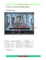
Page 9: ...ayout Note BD is board No Part No Description Type Model PCB Model 1 Main BD 117276 RSAG2 908 1375 1 ROH RSAG7 820 1525 VER A 2 Led IR BD 115206 RSAG2 908 1236 ROH RSAG7 820 1318 3 Keypad BD 115208 RS...

Page 10: ...10 PDP TV Service Manual Hisense Confidential 4 2 Main BD 4 3 Terminal BD...

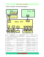
Page 11: ...V 12V power and communication between Main BD and power BD HX2 2X11D500 1 ROH Main BD XP6 Power BD P813 2 Audio output L R TJC3H 4Y 800 850 P ROH Main BD XP8 Speaker L R 3 Buttons TJC10T 3Y 700 P ROH...

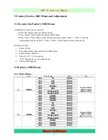
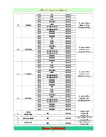
Page 12: ...call up User OSD Menu 3 Select Sound Balance 4 Enter 0 5 3 2 in sequence Note If necessary re do number keys 5 Factory OSD appears 5 2 Factory OSD Menu 5 2 1 White Balance Item Default Value Range No...

Page 13: ...just White Balance Low Brightness Red 125 TV 0 255 125 AV1 0 255 125 AV2 0 255 125 S Video 0 255 124 VGA 0 255 126 Component1 0 255 126 Component2 0 255 126 HDMI1 0 255 126 HDMI2 0 255 5 G Offset 126...

Page 14: ...Industrial Park 5 Hungary Hisense Hungary 6 Australia Hisense Australia 7 France Hisense France 5 2 3 Auto Color For VGA and Component Video sources WB values must be adjusted Before adjusting prepar...

Page 15: ...to Clean Protected by which you can resume the default value To clear the EEPROM a Select the button Clean All b Press VOL button to clear the EEPROM data c Wait for 5 seconds turn off the power d Re...

Page 16: ...nent2 0 1000 0 HDMI1 0 1000 0 HDMI2 0 1000 Min Bright 0 HDMI3 0 1000 Min Brightness 520 TV 0 1000 530 AV1 0 1000 530 AV2 0 1000 530 S Video 0 1000 490 VGA 0 1000 530 Component1 0 1000 530 Component2 0...

Page 17: ...00 HDMI2 0 1000 Contrast Max 600 HDMI3 0 1000 Max Contrast 0 TV 0 1000 0 AV1 0 1000 0 AV2 0 1000 0 S Video 0 1000 0 VGA 0 1000 0 Component1 0 1000 0 Component2 0 1000 0 HDMI1 0 1000 0 HDMI2 0 1000 Sat...

Page 18: ...HDMI3 0 1000 Mid Hue 1000 TV 0 1000 1000 AV1 0 1000 1000 AV2 0 1000 1000 S Video 0 1000 1000 VGA 0 1000 1000 Component1 0 1000 1000 Component2 0 1000 1000 HDMI1 0 1000 1000 HDMI2 0 1000 Hue Max 1000 H...

Page 19: ...Component2 0 100 50 HDMI1 0 100 50 HDMI2 0 100 STD Bright 50 HDMI3 0 100 Brightness of STD mode 50 TV 0 100 50 AV1 0 100 50 AV2 0 100 50 S Video 0 100 50 VGA 0 100 50 Component1 0 100 50 Component2 0...

Page 20: ...ation 45 HDMI3 0 100 Saturation of Movie mode 5 3 3 Sound setting Default Item TV AV S V IDE O Comp onent HDM I VGA Item Range Note 0 0 0 0 0 Volume Min 0 100 When value is 0 Think about the Audio out...

Page 21: ...10 10 Different Values for different Audio Mode Speech Item Range 2 120HZ 10 10 4 500HZ 10 10 0 1 5kHZ 10 10 7 5kHZ 10 10 10 10kHZ 10 10 Different frequencies for different Audio Mode Music Item Range...

Page 22: ...con install the driver Select the default value the driver will be installed step by step 6 1 2 Hardware connecting Connect the unit to your pc with a USB to series port cable USB port connects to the...

Page 23: ...23 PDP TV Service Manual Hisense Confidential...

Page 24: ...After connecting the TV with your PC double click icon open the MtkTool If following error appears it means the related port is not be set properly Ignore these errors click Confirm and enter the MtkT...

Page 25: ...tial 5 Click the browse button to select the bin file that will be updated 6 Click the start button to update software Select mode of Flash chip Communicate port Set Flash Baud Rate Select bin file St...

Page 26: ...o select COM2 in the MtkTool main interface Select the right baud rate according to chip model For this unit chip model is MT538X select 115200 Note Where or not click the Auto Set Flash Baud Rate in...

Page 27: ...e Manual Hisense Confidential Click Browse button find the upgrading program file and select it Press Upgrade button and start upgrading The following interface appears on the screen indicating upgrad...

Page 28: ...oubleshooting for Remote Control Remote control does not work Try new batteries Replace RC Check IR receiver Change Led IR board Change Led IR cable Replace main board Replace battery Replace remote c...

Page 29: ...isense Confidential 7 2 Troubleshooting for Function Key Buttons does not work Check switches Check key board Check Key BD cable Change Key BD cable Replace main board Replace tact switch Replace Key...

Page 30: ...replace IR BD or Keypad PCA TV won t power on Is LED light NO YES Check Power Inlet YES NO Check Power Cord Only one works Replace Main BD Try Power on by RC and Button Neither works Both Work Power...

Page 31: ...Manual Hisense Confidential 7 4 Troubleshooting for Audio No sound Check connecter Check speaker wire Replace main board Reconnect Replace speaker wire YES YES NO NO Check speaker set Replace speaker...

Page 32: ...sense Confidential 7 5 Troubleshooting for TV VGA HDMI input No picture on the screen Check Signal Source Check connect Check cable Replace main board Make sure signal source is available Reconnect Re...

Page 33: ...ense Confidential 7 6 Troubleshooting for YPbPr input No picture on the screen Check Source work or not Check connect Check Wires Green Blue Red Replace main board Check Source Device Reconnect Replac...

Page 34: ...se Confidential 7 7 Troubleshooting for Video S Video input No picture on the screen Check Source work or not Check connect Check Cable Wires Replace main board Check Signal Source Reconnect Replace C...

Page 35: ...35 PDP TV Service Manual Hisense Confidential 7 8 Others Troubleshooting...

Page 36: ...36 PDP TV Service Manual Hisense Confidential 8 Explode View 9 Schematic circuit diagram...

Page 37: ......

Page 38: ...DDC WP PROTECT CEC FUNCTION GPIO_5 GPIO_6 trap mode trap mode U2RX NC NC U2TX NC ADIN1 2 RF_AGC GPIO Definition key pad ADIN0 GPIO Definition GPIO_8 GPIO_9 GPIO_7 PWRDET GPIO_4 GPIO_12 GPIO_13 OPCTRL3...

Page 39: ...V CE21 100uF 16V ADJ GND 1 OUT 2 IN 3 OUT 4 N4 AZ1117 ADJ N4 AZ1117 ADJ GND 1 SD 2 VSENSE 3 VREF 4 VDDQ 5 AVIN 6 PVIN 7 VTT 8 N3 LP2996 N3 LP2996 R31 100K R31 100K CE12 100uF 16V CE12 100uF 16V ADJ GN...

Page 40: ...et 1 us Trap Mode OPCTRL4 OPCTRL5 0 1 A0 1 U8 24CXX U8 24CXX R54 4K7 NC R54 4K7 NC L7 120R L7 120R R62 10K R62 10K TP1 TP1 2 2 3 3 4 4 5 5 9 9 8 8 7 7 6 6 1 1 H5 HOLE GND H5 HOLE GND C44 20pF C44 20pF...

Page 41: ...CAS_ 41 RA4 39 RA10 45 RA8 35 RRAS_ 42 RA5 38 RBA1 44 RA6 37 RBA0 43 RWE_ 40 RA7 36 RA0 47 RA3 51 RA9 34 RA11 33 RCKE 31 RCS_ 46 RCLK0_ 28 RCLK0 29 RA1 49 RA2 50 RVREF0 53 RDQS0 11 RDQM0 13 RDQ0 9 RDQ...

Page 42: ...105 100nF R CAPC1005L HX C105 100nF R CAPC1005L HX 1 2 3 4 XP7 TJC10 4A XP7 TJC10 4A C89 100nF C89 100nF C86 100nF C86 100nF C88 100nF C88 100nF C102 100nF C102 100nF POCE0_ 252 POOE_ 251 PDD0 250 PDD...

Page 43: ...0nF L15 120R NC L15 120R NC C133 100nF 50V C133 100nF 50V C125 100nF NC C125 100nF NC L14 120R L14 120R C124 47nF C124 47nF USB_VRT 68 USB_DM 65 USB_DP 66 AVDD33_USB 67 AVDD12_ADCPLL 162 AVDD12_TVDPLL...

Page 44: ...R146 10K R146 10K C173 1nF C173 1nF C164 1nF C164 1nF CE38 22uF 16V CE38 22uF 16V C171 100pF C171 100pF R156 0R0 R156 0R0 R142 10K NC R142 10K NC L19 120R L19 120R C148 1uF C148 1uF L17 120R L17 120R...

Page 45: ...mH NC 1 2 3 V11 3906 V11 3906 L26A 33uH L26A 33uH R190 0R0 R190 0R0 CE49 220uF 25V CE49 220uF 25V 1 2 VD4 1N4148 VD4 1N4148 C197 10uF 10V C197 10uF 10V C203 1uF C203 1uF R169 1K NC R169 1K NC C188 100...

Page 46: ...HEN R D Suite 406 langfeng Bldg 2 Kefa Road Nanshan District Shenzhen China Tel 86 755 26532018 Fax 86 755 26532013 A3 9 14 Wednesday April 16 2008 LVDS OUT LO LVDS POWER OFF HI LVDS POWER ON Hisense...

Page 47: ...L45 120R L45 120R R225 68R R225 68R L47 120R L47 120R TP14 TP14 L43 120R L43 120R C225 1uF C225 1uF C228 10nF C228 10nF SIGNAL 1 GND 2 SIGNAL 3 GND 4 SIGNAL 5 GND 6 XS2A XS2A C227 4 7nF C227 4 7nF R2...

Page 48: ...8 L WP DISABLE H WP ENABLE NEARLY VGA CON NEARLY IC Hisense Electric Co LTD C252 10nF C252 10nF VD12 1N4148 NC VD12 1N4148 NC L48 120R L48 120R 1 2 D24 15P D24 15P 1 2 D21 15P D21 15P R244 10K R244 10...

Page 49: ...1K 1 2 D60 15P D60 15P C277 100nF C277 100nF R304 100K NC R304 100K NC R267 37K R267 37K R298 100R R298 100R R271 47K R271 47K R291 10K R291 10K 1 2 D39 0 15P D39 0 15P NC 1 NC 2 NC 3 GND 4 SDA 5 SCL...

Page 50: ...C310 100nF C293 100nF C293 100nF R342 15K R342 15K C316 1uF C316 1uF 1 2 D71 15P D71 15P R333 33R R333 33R R309 100R R309 100R C279 10nF C279 10nF R340 100R NC R340 100R NC CE55 100uF 16V CE55 100uF 1...

Page 51: ...lectric Co LTD MARK LABEL CE57 22uF 16V CE57 22uF 16V 1 2 3 V20 3904 V20 3904 R369 10R R369 10R R373 47K R373 47K R359 22K R359 22K R355 0R0 R355 0R0 1 1 U6 LABEL U6 LABEL R368 4K7 R368 4K7 C319 100pF...

Reviews: