background image

CONTENTS 

1. 

X  -  RAY RADIATION PRECAUTION… … … … … … … … … … … … … … … … … … … … … 1 

2. SAFETY PRECAUTION… … … … … … … … … … … … … … … … … … … … … .   … … … … … 1 

3. PRODUCT SAFETY NOTICE… … … … … … … … … … … … … … … … … … … … … … . . … … 2 

4. 

THE ALIGNMENT FLOW CHART … … … … … … … … … … … … … … … … … … … … . . … … 3 

5. INSTALLATION AND SERVICE ADJUSTMENTS… … … … … … … … … … … … … … … … 3 

6. USA CHANNEL FREQUENCY TABLE (181 CH)  … … … … … … … … … … … … … . . . … …   9  

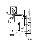
7. WIRING DIAGRAM… … … … … … … … … … … … … … … … … … … … … .   … … . . … … … … 12 

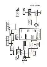
8. BLOCK DIAGRAM… … … … … … … … … … … … … … … … … … … … … .   … … . . . … … . … … 13 

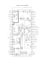
9. IC BLOCK DIAGRAM… … … … … … … … … … … … … … … … … … … … … .   … … . . . … … … 14

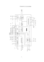
10. TDA9850 BLOCK DIAGRAM


… … … … … … … … … … … … … … … … … … .   … … . . … .… … 15 

11. COMPONENT AND BOTTOM VIEW… … … … … … … … … … … … … … … … … … . . . . … … 16 

12. SCHEMATIC DIAGRAM… … … … … … … … … … … … … … … … … … .   … … … … . . … . … … 23 

13. ELECTRICAL PARTS LIST… … … … … … … … … … … … … … … … … … .   … … … . . … . … … 24 


Summary of Contents for TC14FS68

Page 1: ...E 2 4 THE ALIGNMENT FLOW CHART 3 5 INSTALLATION AND SERVICE ADJUSTMENTS 3 6 USA CHANNEL FREQUENCY TABLE 181 CH 9 7 WIRING DIAGRAM 12 8 BLOCK DIAGRAM 13 9 IC BLOCK DIAGRAM 14 10 TDA9850 BLOCK DIAGRAM 15 11 COMPONENT AND BOTTOM VIEW 16 12 SCHEMATIC DIAGRAM 23 13 ELECTRICAL PARTS LIST 24 ...

Page 2: ... in the parts list 5 Some parts in this receiver have special safety related characteristics for X RAY RADIATION protection For continuous safety parts replacement should be undertaken only after referring to the PRODUCT SAFETY NOTICE below SAFETY PRECAUTION WARNING Service should not be attempted by anyone unfamiliar with the necessary precaution on this receiver The following are the necessary p...

Page 3: ...ts for each exposed metallic part V oltage measured must not exceed 0 3 volts RMS This corresponds to 0 2 milliamp AC Any value exceeding this limit constitutes a potential shock hazard and must be corrected immediately PRODUCT SAFETY NOTICE Many electrical and mechanical parts in the chassis have special safety related characteristics These characteristics are often passed unnoticed by a visual i...

Page 4: ... chassis Checking should be done following the steps below 1 Connect an accurate high voltage meter to the second anode of the picture tube 2 Turn on the receiver Set the BRIGHTNESS and CONTRAST controls to minimum zero beam current 3 High voltage will be measured about 28 5kV 4 Vary the BRIGHTNESS control to both extremes to be sure the high voltage does not exceed the limit under any conditions ...

Page 5: ...Apply 95dBμ 45 75MHz RF signal to the tuner s IFpin through a 1000P ceramic capacitor Connect the DC voltameter s pole to LA76814 pin 47 pole to GND Note For LA76814 ES01 version the voltameter s pole should connect to pin50 3 Adjust T202 with a non inductive screwdriver until the reading on the DC voltameter is DC 3 6V 0 01V B CHECK 1 Prepare the test equipment 2 Use the DC voltameter at DC 200V ...

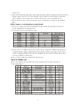
Page 6: ...the ADJ or ADJ button to adjust too 3 In ADJUST mode select the item you want to adjust directly by pressing the button on the Under Adjustment remote controller and use the ADJ or ADJ button to adjust You can press ADJUP or ADJDOWN to select needed adjustment item and use the ADJ or ADJ button to adjust too 4 In SETUP mode select the item you want to adjust by pressing the button ADJUP or ADJDOWN...

Page 7: ... Bias Red Bias Blue Drive Green Drive Red Drive Cross B W 3 Set the value of S BRI 85 then press LINE button Adjust the SCREEN potentiameter clockwise until a slight bright horizontal line appears on the screen Adjust the value of R BIA G BIA and B BIA until the line change white Press LINE button again Then decrease S BRI to a proper value 4 Press LINE button to exit B W BALANCE mode ADJUST MENU ...

Page 8: ...3 UPC1851B Digital OSD 0 Analog 1 Digital Count Down Mode LA76814 0 1 LA76812 0 7 Vertical Synchronization Separate Sense 0 low 1 high OSD Contrast 0 127 LA76814 0 3 FBPBLK SW 0 1 Red Green Definition 0 1 16 17 18 19 20 21 22 23 24 25 26 27 28 29 30 BRIGHT ABL TH EMG ABL DEF BRT ABL DEF MID STP DEF R Y B Y G BL R Y B Y ANG C KILL OFF SND TRAP VOL FIL VIF SYS SW VIDEO LEVEL FM LEVEL POWER OPT POWER...

Page 9: ...phone Password of V CHIP 0 off 1 on 0 1 0 0 0 1 1 1 Volume of H Phone 0 No Woofer 1 Woofer Sensitivity Function 0 off 1 on V CHIP Function 0 off 1 on Stereo Option 0 off 1 on 44 45 COMB OPTION TUNER OPTION 1 0 0 TDF 3M3 1 PHOLIPUV1336B Y C Separate Function 0 off 1 on 46 47 GAME OPTION SCREEN OPTION Game Option 0 on 1 off 0 No Screen 1 Screen When Power On 2 ScreenWhen Power Off 3 Screen When Powe...

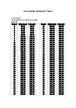
Page 10: ...471 25 475 75 48 675 25 679 75 15 477 25 481 75 49 681 25 685 75 16 483 25 487 75 50 687 25 691 75 17 489 25 493 75 51 693 25 697 75 18 495 25 499 75 52 699 25 703 75 19 501 25 505 75 53 705 25 709 75 20 507 25 511 75 54 711 25 715 75 21 513 25 517 75 55 717 25 721 75 22 519 25 523 75 56 723 25 727 75 23 525 25 529 75 57 729 25 733 75 24 531 25 535 75 58 735 25 739 75 25 537 25 541 75 59 741 25 74...

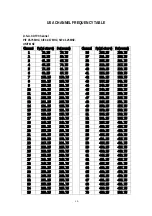
Page 11: ... 367 25 371 75 14 121 25 125 75 49 373 25 377 75 15 127 25 131 75 50 379 25 383 75 16 133 25 137 75 51 385 25 389 75 17 139 25 143 75 52 391 25 395 75 18 145 25 149 75 53 397 25 401 75 19 151 25 155 75 54 403 25 407 75 20 157 25 161 75 55 409 25 413 75 21 163 25 167 75 56 415 25 419 75 22 169 25 173 75 57 421 25 425 75 23 217 25 221 75 58 427 25 431 75 24 223 25 227 75 59 433 25 437 75 25 229 25 2...

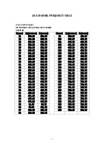
Page 12: ...691 25 695 75 80 559 25 563 75 108 697 25 701 75 81 565 25 569 75 109 703 25 707 75 82 571 25 575 75 110 709 25 713 75 83 577 25 581 75 111 715 25 719 75 84 583 25 587 75 112 721 25 725 75 85 589 25 593 75 113 727 25 731 75 86 595 25 599 75 114 733 25 737 75 87 601 25 605 75 115 739 25 743 75 88 607 25 611 75 116 745 25 749 75 89 613 25 617 75 117 751 25 755 75 90 619 25 623 75 118 757 25 761 75 9...

Page 13: ... 12 ...

Page 14: ...04 N101 LA76814 DEFLECTION PIF SIF VIDEO IR TX MU28P0381 CHROMA VIDEO FM OUT OUT IN V OUT N451 LA7841 H OUT V432 3DD2553 T471 FBT CRT CRT DRIVE B G R BTSC TDA9850 SWITCH TC4053BP BF AUDIO IN VIDEO OUT VIDEO IN POWER V513 2SC4237 B1 130V B3 16V B2 18V B8 25V AC 120V NTSC AUDIO OUT AUDIO AMP LA4287 IN1 IN2 ...

Page 15: ...talGround X RAY KillerFilter ChromaAPC1Filter fsc 3 58MHz Output 3 58MHzCrystal ACCFilter SelectedVideoOutput Video Vertical BUSGround External Video Input Y IN Video VerticalGround InternalVideo Input S_CIN BlackLevelDetector VideoOutput APCfilter VCOCoil2 VCOCoil1 FLLFilter Ext AudioInput SIFOutput 2 5 2 5 2 53 2 56 2 8 2 8 5V 2 12 2 34 4 8 4 8 3 52 1 1 1 15 1 13 0 8 3 16 3 16 3 05 0 2 51 2 63 5...

Page 16: ...2 21 27 OUTL OUTR stereo mono SAP to audio processing C8 SAPwithoutDBX MAD MHA010 C6 C7 18 19 L R L R SAP 17 13 14 15 16 C2 C3 C4 R1 C5 Q1 ceramic resonator 11 C1 composite baseband input STEREODECODER INPUT LEVEL ADJUST NOISE DETECTOR SAP DEMODULATOR DBX STEREO ADJUST SUPPLY STEREO SAP SWITCH TDA9850 DE EMPHASIS LOGIC IC 2 TRANSCEIVER DEMATRIX MODE SELECT 15 ...

Page 17: ...COMPONENT VIEW OF MAIN BORAD 16 ...

Page 18: ......

Page 19: ......

Page 20: ...COMPONENT VIEW OF CRT BORAD 18 ...

Page 21: ...COMPONENT VIEW OF STEREO BORAD 20 ...

Page 22: ...0V1 A101 TUNER IF 33V 5V SDA NC SCL AGC 5V C103 50V2 2 R103 1K R102 100K R101 33K B7 5V C101 16V100 C102 0 01 C434 50V10 B8 25V R434 2W220 T431 JDT1904 L431 ZZ008 C474 250V22 VD474 EU1 R474 1FJ1 R472 1FJ1 VD472 EU2 C472 35V100 B4 24V R567 1 2K C570 10V470 B5 5V N553 AN7805 1 2 3 B6 12V VD552 1N4148 R622 3K V821 2SC R822 4 7K R821 1K C821 50V1 V801 2SC R801 27K R803 220 C805 16V470 R802 68K R804 10...

Page 23: ...0 J PCS 15 R103 R119 R121 R201 R268 R458 R602 R821 R610 R620 R931 R104 R105 R612 R622 18 RT13 1 6W 1K2 J PCS 2 R202 R567 19 RT13 1 6W 1K5 J PCS 3 R722 R1707 R933 20 RT13 1 6W 2K2 J PCS 3 R401 R408 R760 21 RT13 1 6W 2K7 J PCS 3 R244 R1706 22 RT13 1 6W 3K0 J PCS 3 R272 R275 R454 23 RT13 1 6W 3K3 J PCS 4 R402 R742 R743 R820 24 RT13 1 6W 3K9 J PCS 2 R1705 R415 25 RT13 1 6W 4K7 J PCS 20 R274 R724 R736 ...

Page 24: ...S 1 R456 55 RT14 1 4W 15K J PCS 1 R522 56 RT14 1 4W 22K J PCS 2 R515 R556 57 RT14 1 4W 39K J PCS 1 R457 58 RT14 1 4W 220K J PCS 1 R446 1 2W METAL OXIDE FILM RESISTOR 59 RY25 1 2W 1R J PCS 1 R452 RY25 1 2W 270R J PCS 1 R713 61 RY25 1 2W 1K J PCS 1 R433 62 RY26 1 2W 2K7 J PCS 3 R908 R918 R928 63 RY25 1 2W 3K3 J PCS 1 R557 64 RY25 1 2W 47K J PCS 1 R555 65 RY25 1 2W 100K J PCS 1 R552 66 RY25 1 2W 150K...

Page 25: ...ABLE RESISTOR 91 WI06 2 2 2K PCS 1 RP551 DEGAUSSING RESISTOR 94 PTDCA1BF3R0Q100 PCS 1 RT501 CERAMIC CAPACITOR 95 CC1 08A CH 50V 15P J PCS 1 C704 96 CC1 08A CH 50V 18P K PCS 2 C125 C705 97 CC1 06A RH 50V 22P J PCS 1 C209 98 CC1 06A RH 50V 39P J PCS 1 C126 100 CC1 10A RH 50V 470P J PCS 3 C140 C771 C772 101 CT1 06A 2B4 50V 1000P K PCS 3 C123 C453 102 CT1 08A 2F4 50V 0 01µ Z PCS 23 C102 C112 C116 C118...

Page 26: ...76 C601 C602 C611 C621 C733 C734 C806 C807 C808 C809 C810 C811 C823 C825 134 CD110 16V 47µ M PCS 6 C206 C244 C404 C701 C719 135 CD110X 16V 100µ M PCS 9 C101 C115 C450 C612 C613 C622 C623 C631 C805 136 CD110X 16V 220µ M PCS 1 C801 137 CD110 16V 330µ M PCS 1 C933 138 CD110X 16V 470µ M PCS 3 C570 C572 139 CD110 25V 10µ M PCS 2 C931 C932 CD110 25V 330µ M PCS 1 C799 140 CD110X 25V 470µ M PCS 2 C615 C62...

Page 27: ...CL 01B PCS 1 EMC L501 173 HF562Y2R5 PCS 1 EMC L502 DIODE 174 1N4148 PCS 18 VD401 VD402 VD514 VD516 VD552 VD553 VD610 VD611 VD612 VD620 VD621 VD622 VD631 VD801 VD901 VD911 VD921 VD933 1N4002 PCS 1 VD711 175 UZ3 6BSB PCS 1 VD703 176 UZ6 2BSB PCS 1 VD561 177 UZ7 5BSB PCS 1 VD412 178 UZ5 6BSB PCS 1 VD499 179 1Z75 PCS 1 VD452 180 EM01Z PCS 1 VD451 181 RU4AM PCS 2 VD551 VD554 182 EU2 PCS 2 VD472 VD555 1...

Page 28: ...MIC OSC 210 JA25D 3 58MHZ PCS 1 EMC G201 211 32 768KHz PCS 1 EMC G701 212 CSB503F58 PCS 1 X01 SAW FILTER 213 D45U PCS 1 EMC Z101 PUSH SWITCH 214 KAN C202 5 PCS 6 S1701 S1702 S1703 S1704 S1705 S1706 FUSE 215 125V 250V 3 15A PCS 1 F501 TUNER 216 TEDH9 243A PCS 1 EMC A101 POWER SWITCH KDC A06 0 PCS 1 CRT SOCKET 218 GZS10 2 AC2DG PCS 1 XS901 RCA JACK 219 AV302 1 PCS 1 XS801 XS801A 220 S JACK PCS 1 XS8...

Page 29: ... RIVET 228 XRY1 6 2 8BD PCS 13 L501 1 L501 2 L502 1 L502 2 T511 1 T511 7 T511 8 T511 14 T471 1 T471 2 T471 4 T471 8 T471 10 229 XRY2 5 3 5BD PCS 18 C507 C507 V513 1 V513 2 V513 3 POWER RADIATOR4 6 V432 1 V432 2 V432 3 H V RADIATOR4 5 6 7 RL551 1 RL551 2 RL552 1 RL552 2 THE LEFT POWER MAGNIFY RADIATOR1 2 THE LEFT POWER MAGNIFY RADIATOR1 2 CONNECTOR 231 TJC3 5A PCS 1 XS403 233 TJC2 5A PCS 1 XS402 23...

Page 30: ...1 252 RSR5 861 0135 PCS 1 253 RSAG7 308 043 PCS 1 254 PCS 255 PCS FUSE SUPPORTER 256 RSR7 736 0102 PCS 2 FOR FUSE SPACER 257 RSR7 854 0108 PCS 1 FOR THE WIRE OF H DRIVER TRANSFORMER BRACKET 258 RSR8 078 0207 PCS 1 SPRING CRT GND ASSY 259 RSR8 381 0105 PCS 1 DEGAUSSING COIL CLIP 260 RSAG8 667 003 PCS 4 for degaussing coil CLIP 261 RSAG8 667 004 PCS 7 262 SPRING 263 RSR8 382 0102 PCS 1 LENS LED 264 ...

Page 31: ...CS 4 FOR CRT 279 RSR8 610 0137 PCS 2 280 RSR8 683 0128 PCS 3 281 RSR8 942 0106 PCS 1 282 RSR7 844 0113 PCS 1 283 Ф3 3 140HV GB97 1 85 PCS 1 GASKET 284 RSAG8 870 188 PCS 1 TOP 285 RSAG8 870 189 PCS 1 BOTTOM SUPPORTOR FOR CRT 286 RSR6 150 0118 PCS 4 FOR CRT SPONGE 287 40X15X5 mm PCS 1 288 AC CORD CLIP 289 QH009 PCS 1 290 LABEL 291 E RSR8 808 142 PCS 1 CRT 292 RSAG8 817 008 PCS 1 293 SCREW 294 295 SJ...

Page 32: ... 8 302 SJ2835 87 PCS 1 M3X10 303 SJ2835 87 PCS 2 M3X12 304 NUT M3 PCS 5 305 306 307 WRAPPING BOX 308 E RSR8 865 1077 PCS 1 PLASTIC BAG 309 RSAG8 840 005 PCS 1 FOR THE USER S MANUAL 310 RSAG8 840 009 PCS 1 FOR THE TV SET BOPP ADHESIVE TAPE 311 24X400mm PCS 2 312 24X100mm PCS 2 313 72X900mm PCS 1 TV USE DIRECTORY 314 IES031110 PCS 1 RC TRANSMITTER 315 HYDFSR 0073 PCS 1 WITH PACKING BAG Page 10 of 22...

Page 33: ...NO DESCRIPTION UNIT QTY LOCATION Page 11 of 22 ...

Reviews: