background image

PRODUCT NAME

Hitachi Slide Compound Miter Saw

Models   

C 8FSE, C 8FSHE

    Cutting various types of wood workpieces
    Cutting workpieces of plywood, decoration panels, soft fiberboards and hard boards
  Cutting aluminum sashes

The new slide compound miter saws Models C 8FSE and C 8FSHE are developed to bring to the European
market at the prices as low as the competitors’ products. The Model C 8FSHE is equipped with a laser marker
for easier alignment with the ink line and an LED light to illuminate the working surface brightly. In addition, the
Model C 8FSE that is mostly the same as the Model C 8FSHE except that it is not equipped with the laser
marker and the LED light is introduced in tandem with the Model C 8FSHE. With the new Models C 8FSE and
C 8FSHE, we aim to enhance the share of the Hitachi slide compound miter saw series.

MARKETING OBJECTIVE

APPLICATIONS

SELLING POINTS

International Sales Division

SPECIFICATIONS AND PARTS ARE SUBJECT TO CHANGE FOR IMPROVEMENT.

LIST Nos.
C 8FSE: E948
C 8FSHE: E949
Feb. 2008

C 8FSHE

C

<Same features as the conventional models>

Slide cutting
Press cutting
Miter cutting
Right and left bevel cutting
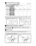
Compound miter and left bevel cutting
Splinter guard, also serving for cut alignment
Groove cutting

[ NEW FEATURES ]


Laser marker (Only the Model C 8FSHE)


LED light (Only the Model C 8FSHE)


Lightweight


Positive angle stoppers


Bevel cutting range: Left 48

°

 to right 5

°


High dust collecting performance


Soft grip handle


Legible scale

Summary of Contents for C 8FSE

Page 1: ...with the laser marker and the LED light is introduced in tandem with the Model C 8FSHE With the new Models C 8FSE and C 8FSHE we aim to enhance the share of the Hitachi slide compound miter saw series MARKETING OBJECTIVE APPLICATIONS SELLING POINTS International Sales Division SPECIFICATIONS AND PARTS ARE SUBJECT TO CHANGE FOR IMPROVEMENT LIST Nos C 8FSE E948 C 8FSHE E949 Feb 2008 C 8FSHE C Same f...

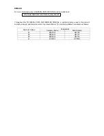
Page 2: ...view_export Throughout this TECHNICAL DATA AND SERVICE MANUAL a symbol s is are used in the place of company name s and model name s of our competitor s The symbol s utilized here is are as follows Competitors Symbols Utilized Company Name Model Name P1 DEWALT DW707 P2 DEWALT DW777 P3 DEWALT DW712 B BOSCH GCM8S ...

Page 3: ...w blade lower limit position 16 2 Confirmation for use of sub fence Optional accessory 16 3 Position adjustment of laser line Only the Model the C 8FSHE 17 4 How to use the vise assembly 18 5 Adjustment of table insert position 18 6 Cutting operation 19 ADJUSTMENT OF COMPONENTS 24 1 Bevel angle adjustment 24 2 Ball bushing Linear bearing 24 PACKING 25 REPAIR GUIDE 26 1 Precautions in disassembly a...

Page 4: ...ide The laser line is adjusted to the width of the saw blade at the time of factory shipment Depending upon the user s cutting choice the laser line can be aligned with the left side of the cutting width saw blade or the ink line on the right side Adjust the position of the laser line according to Position adjustment of laser line on page 17 LED light Only the Model C 8FSHE The Model C 8FSHE is eq...

Page 5: ...ing performance of the Models C 8FSE and C 8FSHE are remarkably higher than the other models thanks to the adoption of new dust guide and gear case HITACHI C 8FSE C 8FSHE C 8FB2 P1 and P2 P3 B Press cutting 1 Size of the workpiece 60 mm x 60 mm 2 3 8 x 2 3 8 75 0 25 0 5 9 31 3 62 2 Slide cutting 2 Size of the workpiece 30 mm x 150 mm 1 3 16 x 5 29 32 80 0 45 0 11 0 72 3 74 5 Soft grip handle The h...

Page 6: ... of the head and the top surface of the workpiece at the lower limit position of the saw blade as shown in Fig 6 b See the Instruction Manual Lower limit position of saw blade when cutting a large workpiece Please note that when cutting in this position it is necessary to use an auxiliary board of 30 mm 1 3 16 wide so that the workpiece on the fence side can be cut fully in width Press cutting HIT...

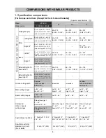
Page 7: ...ng the turn table right and left The maximum cutting dimensions in in Table 4 are those obtained by adjusting the lower limit position of the saw blade indicated in Fig 6 b also with an auxiliary board Right and left bevel cutting HITACHI C 8FSE C 8FSHE C 8FB2 P1 and P2 P3 B Left 45 Height x Width H x W 45 x 312 1 25 32 x 12 1 4 50 x 252 1 15 16 x 9 15 16 with aux board width 30 1 3 16 45 x 305 1 ...

Page 8: ...ng for cut alignment When cutting the ends of a workpiece splinters may drop on the saw blade and be cut into pieces The Models C 8FSE and C 8FSHE are equipped with a splinter guard to prevent such splinter cutting Refer to SELLING POINTS Safe cutting is also ensured in bevel cutting because the splinter guard is tilted with the saw blade Groove cutting The Models C 8FSE and C 8FSHE can cut groove...

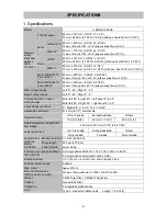
Page 9: ...d miter bevel cutting ranges Miter left 45 to right 45 left bevel 0 to 45 Miter left 45 to right 45 right bevel 0 to 5 Angle stopper positions 0 Right left 15 22 5 31 6 and 45 Applicable saw blade 216 mm 8 1 2 external dia U S A Canada Europe Australia Others Saw blade bore 15 9 mm 5 8 30 mm 1 11 64 25 4 mm 1 External diameter of applicable saw blades 200 mm to 220 mm 7 7 8 to 8 21 32 U S A Canada...

Page 10: ...2 TCT saw blade 30 mm 1 11 64 bore NT36 Code No 998861 for Europe AUS for wood cutting 216 mm 8 1 2 TCT saw blade 25 4 mm 1 bore NT36 Code No 996210 for others for wood cutting 216 mm 8 1 2 TCT saw blade 15 9 mm 5 8 bore NT60 Code No 998862 for USA CAN for aluminum sash cutting 216 mm 8 1 2 TCT saw blade 30 mm 1 11 64 bore NT60 Code No 998863 for Europe AUS for aluminum sash cutting 216 mm 8 1 2 T...

Page 11: ...1 32 50 x 170 1 15 16 x 6 11 16 with aux board 30 1 3 16 48 x 190 1 7 8 x7 15 32 48 x 190 1 7 8 x 7 15 32 42 x 190 1 21 32 x 7 15 32 Maximum cutting dimensions Height x Width mm inch Miter left right 45 bevel right 5 60 x 220 2 3 8 x 8 21 32 70 x 170 2 3 4 x 6 11 16 with aux board 30 1 3 16 Groove cutting width Possible with bolt height adjustment Impossible Impossible Possible with screw height a...

Page 12: ... 1 8 x 22 1 16 x 23 7 32 460 x 560 x 590 18 1 8 x 22 1 16 x 23 7 32 450 x 610 x 510 17 23 32 x 24 x 20 3 32 Product weight kg lbs C 8FSE 14 31 C 8FSHE 14 5 32 14 5 32 14 31 15 33 1 Standard accessories 216 mm 8 1 2 TCT saw blade NT24 for wood cutting 1 Dust bag 1 Vise ass y 1 10 mm box wrench 1 Holder 1 Sub fence 1 for USA CAN 216 mm 8 1 2 TCT saw blade NT24 for wood cutting 1 Hex bar wrench 2 Fen...

Page 13: ...20 1 25 32 x 8 21 32 50 x 170 1 15 16 x 6 11 16 with aux board 30 1 3 16 45x220 1 25 32 x8 21 32 50 x 212 1 15 16 x 6 11 32 Maximum cutting dimensions Height x Width mm inch Miter left right 45 bevel right 5 60 x 220 2 3 8 x 8 21 32 70 x 170 2 3 4 x 6 11 16 with aux board 30 1 3 16 Groove cutting width Possible with bolt height adjustment Possible with screw height adjustment Possible with screw h...

Page 14: ...55x500 20 15 32 x 29 23 32 x 19 11 16 580x720x555 22 27 32 x 28 11 32 x 21 27 32 Product weight kg lbs C 8FSE 14 31 C 8FSHE 14 5 32 17 5 38 6 19 5 43 Standard accessories 216 mm 8 1 2 TCT saw blade NT24 for wood cutting 1 Dust bag 1 Vise ass y 1 10 mm box wrench 1 Holder 1 Sub fence 1 for USA CAN 216 mm 8 1 2 TCT saw blade NT24 for wood cutting 1 Dust bag 1 10 mm box wrench 1 Vise ass y 1 Slide fe...

Page 15: ... dangers inherent in the use of any slide compound miter saw cannot be completely eliminated Accordingly general precautions and suggestions for the use of electric power tools and specific precautions and suggestions for the use of the slide compound miter saw are listed in the Instruction Manual to enhance the safe efficient use of the tool by the customer Salespersons must be thoroughly familia...

Page 16: ...ear case Please instruct users to strictly observe the 11 items of precautions in warning label A shown above 3 Caution labels A and B at the front of the base Caution label A at the front of the base For the U S A Canada Europe Australia and Asia Caution label B at the front of the base For China Fig 12 e Fig 13 Fig 14 a Fig 14 b ...

Page 17: ...th the Class II requirements of the standard specified in Relative standards The Class II laser is defined as follows The laser power is low and it is safe by the protective measures such as blinking However it is dangerous if the operator s eyes are exposed directly to the laser for a protracted period The operator can use the laser equipment without particular training and instruction The amount...

Page 18: ...ther Indoor under fine weather Near the window under cloudy weather Indoor under cloudy weather Near the window under cloudy weather just before the sunset Ink line is invisible Laser line Invisible Visible Visible Visible Visible Glaring Glaring The working environment where the illuminance is 200 luxes or less is dark and difficult to operate the Model C 8FSHE The laser line is invisible under d...

Page 19: ...f sub fence Optional accessory The sub fence is optionally available located at the front right of the base Use the sub fence for miter cutting and right bevel cutting The sub fence supports the workpiece widely for stable cutting In the case of left bevel cutting raise the sub fence as illustrated in Fig 17 and turn it counterclockwise For the U S A and Canada the Models C 8FSHE and C8FSE are equ...

Page 20: ...errors WARNING Make sure before plugging the power plug into the receptacle that the main body and the laser marker are turned off Exercise utmost caution in handling a switch trigger for the position adjustment of the laser line as the power plug is plugged into the receptacle during operation If the switch trigger is pulled inadvertently the saw blade can rotate and result in unexpected accident...

Page 21: ... are positioned so that there is no chance that the saw blade will come in contact with either side of the saw blade slot even if the machine is used for 45 bevel cutting Before operating the machine adjust the position of the table inserts so that the sides of the saw blade align with the edges of the table inserts according to the following procedure First loosen the three 6 mm machine screws th...

Page 22: ...pull the saw blade section in the arrow direction toward the operator 3 Push the handle downward and cut the workpiece press cutting For Europe and Australia Push the handle downward while holding down the lock lever with your thumb and cut the workpiece CAUTION If the handle is pushed down forcibly and excessively fast it could cause the saw blade vibration and partial sliding which would leave u...

Page 23: ...uses the safety cover to be caught in the cutting groove of the workpiece and to contact the saw blade CAUTION When cutting a workpiece of 50 mm 1 15 16 height in the left 45 bevel cutting position or a workpiece of 70 mm 2 3 4 height in the right 5 bevel cutting position adjust the lower limit position of the motor head so that the gap between the lower edge of the motor head and the workpiece wi...

Page 24: ...ns 1 and 4 in Fig 26 To process crown molding at positions 2 and 3 in Fig 26 Type of crown molding Miter angle setting Bevel angle setting Miter angle setting Bevel angle setting 45 type Right 35 3 mark Left 30 mark Left 35 3 mark Left 30 mark 38 type Right 31 6 mark Left 33 9 mark Left 31 6 mark Left 33 9 mark 30 and 33 9 left slant setting method 1 Loosen the clamp lever and slant to the left a ...

Page 25: ...blade Mount them to both sides the base as shown in Fig 32 a After mounting tighten the 6 mm knob bolts to secure the crown molding stoppers Optional accessories used Crown molding vise ass y including crown molding stopper L Crown molding stopper L Crown molding stopper R 2 The crown molding vise B optional accessory can be mounted on either the left fence fence B or the right fence fence A It ca...

Page 26: ...he crown molding vise ass y to a position where it will not contact the saw blade Position crown molding with its WALL CONTACT EDGE against the guide fence and its CEILING CONTACT EDGE against the crown molding stoppers as shown in Fig 32 b Adjust the crown molding stoppers according to the size of the crown molding Tighten the 6 mm wing bolt to secure the crown molding stoppers Refer to the follo...

Page 27: ...s widely used in automated machine tools The advantage of the ball bushing is that its friction coefficient remains largely unchanged even when the load is increased ensuring smooth sliding movement In addition slide pipe B made of bearing steel and heat treated to a high degree of hardness HRC 62 to 65 is highly resistant to wear Sales persons should have a good understanding of the structure and...

Page 28: ... position Fig 35 2 How to install packings C and D Put the main body mounted with packings A and B in the carton box aligning with the base packing and the inner frame Fig 36 Put packing C in the left side of the carton box on the top of holder A Put packing D in the right side of the carton box on the top of the switch handle Place the accessories in the space at the rear of the base Fig 37 3 How...

Page 29: ...emove the Flat Hd Screw M6 x 25 51 then remove the Sub Fence 50 and the Plate 49 3 Remove the four Bolts M8 x 35 43 Spring Washer M8 44 and Bolt Washer M8 45 And then remove Fence A 55 and Fence B 47 4 Loosen the Clamp Lever 2 and remove the Machine Screw W Washers M4 x 12 Black 1 Turn the Bolt Left Hand D10 3 to remove from Holder A 124 5 Remove the Hex Socket Set Screw M6 x 8 121 and tap the end...

Page 30: ... 27 Fig 39 a Fig 39 b ...

Page 31: ...Screw W Washers M4 x 12 Black 111 to remove the Nylon Clip 112 Remove the Machine Screw W Washers M4 x 12 Black 195 and remove the Nylon Clip 196 from the Gear Case 198 head 2 Push out the Cord Bush 154 from the inside of the Housing Ass y 155 Disconnect the connector of the Switching Power Supply Ass y 165 and the Laser Marker 107 Open the Cord Bush 154 to remove it from the cord of the Laser Mar...

Page 32: ...older A 124 with a plastic hammer to remove the Ball Bushing 114 8 Remove the Seal Lock Hex Socket Set Screw M6 x 10 118 from Holder A 124 Remove the Bushing 115 from Holder A 124 NOTE Prepare a shaft of 25 mm in diameter and 50 mm in length Make the shaft contact with the end surface of the Bushing 115 and lightly tap the shaft with a plastic hammer to remove the Bushing 115 from Holder A 124 Fig...

Page 33: ...emove the Lock Lever 177 and the Spring 176 4 Remove the two Special Screws M6 205 and remove the Lock Lever 204 and the Lock Lever Spring 203 5 Disassembly of the Armature Ass y 187 a Remove the Housing Ass y 155 from the Gear Case 198 according to the above step 4 1 2 If the Rubber Bushing 186 stays in the Housing Ass y 155 remove it with long nose pliers b Remove the Armature Ass y 187 by gentl...

Page 34: ...d Internal Wire G 169 are provided with a claw to prevent coming off of the connector When removing the Stator Ass y 181 and Internal Wire G 169 from the Switch 3P Faston Type W O Lock 170 pull out the Stator Ass y 181 and Internal Wire G 169 while pressing the claw 7 Disconnect the faston of the Switching Power Supply Ass y 165 from the two Switches W Cover 167 for the Laser Marker 107 and Light ...

Page 35: ... can be removed together with the Laser Marker 107 NOTE At this time the Spring 100 and the Clutch Spring 101 pop out Be careful not to lose them 4 Remove the Clutch Screw 96 Then the Laser Marker 107 can be removed from Holder B 106 NOTE At this time the two Springs 102 pop out Be careful not to lose them 7 Vise ass y 1 Remove the Wing Bolt M6 x 15 36 to remove the Vise Shaft 39 2 Remove the Mach...

Page 36: ...ing or reassembling the Liner 54 ensure that it is positioned and assembled as illustrated in Fig 46 In addition coat 10 grams of Hitachi Motor Grease on the liner sliding portion of the Turn Table 13 4 When replacing the Laser Marker 107 screw the two Seal Lock Hex Socket Set Screws M5 x 6 103 into the Laser Marker 107 To adjust the accuracy of the Laser Marker 107 easily protrude the tips of the...

Page 37: ...HE and unplug the power cord plug from the receptacle before replacing the Laser Marker 107 and the Switching Power Supply Ass y 165 Do not disconnect the connector that connects the Laser Marker 107 with the Switching Power Supply Ass y 165 while the Laser Marker 107 is lighting Otherwise the Laser Marker 107 may be damaged due to surge electricity stored in the Switching Power Supply Ass y 165 D...

Page 38: ... 35 Model C 8FSHE for Europe Australia and Asia Model C 8FSE for the U S A and Canada Model C 8FSE for Europe Australia and Asia Fig 48 b Fig 49 a Fig 49 b ...

Page 39: ... 36 2 Actual wiring diagram Model C 8FSHE for the U S A and Canada Model C 8FSHE for Europe Australia and Asia Fig 50 a Fig 50 b ...

Page 40: ... 37 Model C 8FSE for the U S A and Canada Model C 8FSE for Europe Australia and Asia Fig 51 a Fig 51 b ...

Page 41: ... y 87 and after disassembly reassembly and adjustment of the Ball Bushing 114 Adjust the squareness rated value 0 15 100 mm by moving the fences along the saw blade dummy disc First adjust the squareness between the saw blade and either fence Then adjust flatness of the two fences by applying a straight edge to the right and left fence surfaces Finally apply a square to the fence surface that has ...

Page 42: ...y with a soft cloth 1 Swiveling section of the gear case Coat machine oil on the swiveling and sliding portions of the Gear Case 198 and Hinge A Ass y 87 2 Vise section Coat machine oil on the screw thread portion of the Knob Bolt M10 x 66 35 of the Vise Ass y 42 3 Holder A Coat machine oil on the swiveling and sliding portions of Holder A 124 and the Hinge Shaft A 9 7 Product precision On complet...

Page 43: ... in parallel when the Adjuster 88 is turned clockwise and shift to the left when turned counterclockwise CAUTION Exercise utmost caution in handling the switch trigger for the position adjustment of the laser line as the power plug is plugged into the receptacle during operation If the switch trigger is pulled inadvertently the saw blade can rotate and result in unexpected accidents Do not stare i...

Page 44: ...150 mm 5 15 16 in width with the vise and perform right angle cutting At this time check that Plate A 105 Cover A 104 and the inlet of a hex bar wrench at Hinge A Ass y 87 Fig 57 a are closed to prevent saw dust from entering the laser marker If they are not closed block them with tapes 2 Light up the Laser Marker 107 with the workpiece held in the vise Turn the Adjuster 88 to shift the laser line...

Page 45: ...applied to the entire cutting surface If the laser beam is applied to the cutting surface in parallel the fine fuzz reflects the laser beam and the entire cutting surface becomes bright 5 Make a right angle ink line on the workpieces of 20 mm 13 16 in height and 150 mm 5 15 16 in width and 60 mm 2 3 8 in height and 150 mm 5 15 16 in width respectively Adjust the laser marker and perform cutting If...

Page 46: ...urface defects on Washer D 221 and repair with a file as necessary Replace Washers D 221 c Inaccurate squareness between fence A and fence B and the saw blade 0 15 100 Fig 60 Loosen the Bolt M8 x 35 43 and adjust as necessary Replace Fence A 55 and Fence B 47 d Surfaces of fence A and fence B are not accurately aligned causing workpiece to deviate from proper squareness 0 10 or less Fig 61 Loosen ...

Page 47: ...e or sluggish movement As a result components may be deformed because of unstable gear case or because the operator must apply excessive pressure during operation Check the fitting surfaces of Hinge A Ass y 87 Gear Case 198 and Hinge Shaft A 92 for any foreign substance such as cutting dust and remove it as necessary i Excessively fast cutting speed causes deflection of saw blade and inaccurate cu...

Page 48: ...ches 0 02 43 Fig 64 Repair impact marks or scratches at Washer D 221 Replace them if necessary e Improper slide cutting technique See paragraph Slide Cutting Do not apply unnecessary force for successful slide cutting f Inaccurate squareness between turn table and saw blade causing saw blade to cut at an improper angle and make cutting marks 0 15 100 Fig 59 Same as Item 1 a g Excessively fast cutt...

Page 49: ...upply Check power supply voltage Connect the power cord to power supply b Carbon brush wear exceeds allowable limit 5 mm Check the Carbon Brushes 160 for wear Replace the Carbon Brushes 160 c Contact failure of the switch Check the Switch 3P Faston Type W O Lock 170 for conductivity Replace the Switch 3P Faston Type W O Lock 170 5 Saw blade runs too slow 4 950 min 1 or less a Power supply voltage ...

Page 50: ... does not match the ink line Only Model C 8FSHE a Ink line is not right angle Make a correct ink line again b Laser marker accuracy is not adjusted properly 0 35 100 Fig 65 and Fig 66 Readjust the accuracy of the laser marker Refer to Adjustment of laser marker accuracy c Product accuracy is not good Readjust the accuracy of the product and the laser marker If the forward position of the laser lin...

Page 51: ...ndle Ass y Ball Bearing 6003VV Ball Bearing 608VV Handle Cover Cord Cord Armor Switching Power Supply Switch Light H Ass y Switch W Cover Set Pin Hinge Shaft A Fence A Fence B Shaft B Spring Bearing Holder Ball Bearing 6000VV Ball Bearing 608VV Support Liner Spacer A Housing Ass y Stator Ass y Armature Ass y Holder B Laser Marker Hinge A Ass y Ball Bushing Holder A Turn Table Base Ass y Gear Case ...

Page 52: ...ence Guard Vise Plate Vise Shaft Spindle Ass y Ball Bearing 6003VV Ball Bearing 608VV Handle Cover Cord Cord Armor Switch Set Pin Hinge Shaft A Fence A Fence B Shaft B Spring Bearing Holder Ball Bearing 6000VV Ball Bearing 608VV Support Liner Spacer A Housing Ass y Stator Ass y Armature Ass y Hinge A Ass y Ball Bushing Holder A Turn Table Base Ass y Gear Case General assembly STANDARD REPAIR TIME ...

Page 53: ... 21 23 26 25 24 30 31 27 28 29 34 32 33 7 54 48 49 50 47 35 37 38 40 41 36 39 46 43 51 55 56 57 58 59 53 13 22 8 8 8 8 42 52 7 7 44 45 44 45 601 602 603 604 605 612 613 615 616 618 611 619 606 611 614 617 607 608 609 610 606 620 621 622 623 624 625 627 628 629 630 631 630 632 626 601 604 633 607 620 621 626 ...

Page 54: ...C 8FSHE 81 83 85 87 88 92 89 90 91 93 95 94 96 97 98 106 99 100 101 107 103 102 103 102 104 105 82 109 110 111 112 86 113 114 81 115 116 117 118 119 120 121 122 123 124 125 86 82 82 108 82 84 2 08 2 ...

Page 55: ...186 197 195 196 198 188 189 190 121 194 193 192 191 206 207 199 201 200 202 208 209 221 223 180 151 152 153 154 155 156 157 158 159 160 161 151 165 167 168 169 170 162 163 164 210 211 213 214 215 216 218 222 219 217 220 203 204 205 212 501 502 221 166 173 174 2 08 ...

Page 56: ... 489 RETAINING RING E TYPE FOR D5 SHAFT 1 23 322 283 SIDE HANDLE 1 24 321 339 LEVER SHAFT 1 25 321 338 LEVER 1 26 321 340 SPRING D 1 27 CAUTION LABEL D 1 27 CAUTION LABEL C 1 28 329 415 SHAFT C 1 29 987 860 SEAL LOCK HEX SOCKET SET SCREW M6X6 1 30 321 417 SPRING E 1 31 322 280 STOPPER A 1 32 324 395 COVER B 1 33 875 249 THRUST WASHER 1 34 321 336 PIN COVER 1 35 302 522 KNOB BOLT M10X66 1 36 301 80...

Page 57: ... 302 518 STOPPER PIN ASS Y 1 INCLUD 94 96 305 180 CLUTCH SCREW 1 97 305 179 CLUTCH SPRING 1 98 962 614 ADJUSTING WASHER B T0 5 1 99 319 268 PLATE B 1 100 319 267 SPRING 1 101 305 179 CLUTCH SPRING 1 102 319 267 SPRING 2 103 319 541 SEAL LOCK HEX SOCKET SET SCREW M5X6 2 104 319 271 COVER A 1 105 322 291 PLATE A 1 106 319 269 HOLDER B 1 107 329 863 LASER MARKER 1 108 949 215 MACHINE SCREW M4X8 10 PC...

Page 58: ... 999 021 CARBON BRUSH 1 PAIR 2 FOR USA CAN 161 931 266 BRUSH CAP 2 162 303 970 TAPPING SCREW CLASS 2 D4X14 1 163 301 653 TAPPING SCREW W FLANGE D4X20 BLACK 7 164 329 438 HANDLE COVER 1 165 329 488 SWITCHING POWER SUPPLY ASS Y 1 165 329 487 SWITCHING POWER SUPPLY ASS Y 1 FOR USA CAN 166 324 518 FERRITE CORE 1 167 319 503 SWITCH W COVER 2 168 959 141 CONNECTOR 50092 10 PCS 2 FOR USA CAN 169 329 461 ...

Page 59: ... WASHER M6 10 PCS 1 203 329 463 LOCK LEVER SPRING 1 EXCEPT FOR USA CAN KUW CHN HKG THA INA SIN 204 329 462 LOCK LEVER 1 EXCEPT FOR USA CAN KUW CHN HKG THA INA SIN 205 322 950 SPECIAL SCREW M6 2 EXCEPT FOR USA CAN KUW CHN HKG THA INA SIN 206 328 922 HITACHI PLATE 1 207 308 259 BOLT W WASHERS M6X16 BLACK 1 208 321 364 DUST GUIDE 1 209 312 492 GUIDE HOLDER 1 210 998 335 BOLT LEFT HAND W WASHER M7X17 ...

Page 60: ... WASHERS M4X10 BLACK 1 617 318 967 VISE SHAFT 1 618 321 551 KNOB BOLT M10X54 1 619 329 426 CROWN MOLDING VISE ASS Y 1 INCLUD 606 611 620 974 561 STOPPER 1 621 949 404 WING BOLT M6X20 10 PCS 1 622 321 390 CROWN MOLDING STOPPER HOLDER 1 623 CROWN MOLDING STOPPER R 1 624 301 806 WING BOLT M6X15 1 625 321 373 CROWN MOLDING STOPPER R ASS Y 1 626 HOLDER ASS Y 1 INCLUD 627 632 627 321 549 HOLDER 2 628 94...

Page 61: ...7 21 23 26 25 24 29 30 27 28 33 31 32 7 53 47 48 49 46 34 36 37 39 40 35 38 45 42 50 54 56 57 58 52 13 22 8 8 8 8 41 51 7 7 612 613 615 616 618 611 619 606 611 614 617 601 602 603 604 605 601 604 607 608 609 610 606 620 621 622 623 624 625 627 628 629 630 631 630 632 626 633 607 620 621 626 55 43 44 43 44 ...

Page 62: ...C 8FSE 88 85 86 87 90 89 91 93 92 94 95 96 83 97 99 98 100 101 102 103 104 105 106 107 108 109 110 92 92 81 82 83 84 2 08 2 ...

Page 63: ...77 178 179 180 189 190 182 183 184 106 188 187 186 185 191 192 193 195 194 196 200 201 213 215 174 151 152 153 154 155 156 157 158 159 160 164 165 166 161 162 202 203 205 206 207 208 210 214 211 209 212 197 198 199 204 501 502 213 163 169 3 2 08 ...

Page 64: ...D5 SHAFT 1 23 322 283 SIDE HANDLE 1 24 321 339 LEVER SHAFT 1 25 321 338 LEVER 1 26 321 340 SPRING D 1 27 329 415 SHAFT C 1 28 987 860 SEAL LOCK HEX SOCKET SET SCREW M6X6 1 29 321 417 SPRING E 1 30 322 280 STOPPER A 1 31 324 395 COVER B 1 32 875 249 THRUST WASHER 1 33 321 336 PIN COVER 1 34 302 522 KNOB BOLT M10X66 1 35 301 806 WING BOLT M6X15 1 36 SCREW HOLDER 1 37 949 432 BOLT WASHER M6 10 PCS 1 ...

Page 65: ...0 435Z CORD 1 CORD ARMOR D10 1 FOR GBR 230V 94 500 447Z CORD 1 CORD ARMOR D10 1 FOR SUI 94 500 434Z CORD 1 CORD ARMOR D10 1 FOR USA CAN 94 930 055 CORD 1 CORD ARMOR D10 1 FOR VEN 94 500 439Z CORD 1 CORD ARMOR D10 1 FOR AUS 94 500 423Z CORD 1 CORD ARMOR D10 1 FOR KUW SIN 94 500 456Z CORD 1 CORD ARMOR D10 1 FOR CHN 94 500 455Z CORD 1 CORD ARMOR D10 1 FOR THA 94 500 234Z CORD 1 CORD ARMOR D10 1 FOR I...

Page 66: ... SUPPRESSOR 110V 1 FOR GBR 110V VEN TPE 169 329 439 CAP 1 170 323 433 SPRING 1 171 323 432 LOCK LEVER 1 172 329 436 FAN GUIDE 1 173 960 108 HEX HD TAPPING SCREW D4X60 2 174 931 867 BRUSH TERMINAL 2 175 340 729C STATOR ASS Y 110V 1 INCLUD 174 175 340 729D STATOR ASS Y 120V 1 INCLUD 174 175 340 729E STATOR ASS Y 220V 230V 1 INCLUD 174 175 340 729F STATOR ASS Y 240V 1 INCLUD 174 176 608 VVM BALL BEAR...

Page 67: ...OLT LEFT HAND W WASHER M7X17 5 1 203 TCT SAW BLADE 216MM D15 88 HOLE NT24 1 203 TCT SAW BLADE 216MM D25 4 HOLE NT24 1 203 TCT SAW BLADE 216MM D30 HOLE NT24 1 204 976 819 COLLAR B FOR D25 4 HOLE 1 FOR VEN KUW IND INA CHN THA TPE SIN KOR 204 974 663Z COLLAR A FOR D30 HOLE 1 FOR EUROPE AUT GBR FIN DEN SWE NOR SUI AUS 205 949 322 FLAT HD SCREW M4X10 10 PCS 2 206 307 731 COVER 1 207 329 412 LOWER GUARD...

Page 68: ...4X10 BLACK 1 617 318 967 VISE SHAFT 1 618 321 551 KNOB BOLT M10X54 1 619 329 426 CROWN MOLDING VISE ASS Y 1 INCLUD 606 611 620 974 561 STOPPER 1 621 949 404 WING BOLT M6X20 10 PCS 1 622 321 390 CROWN MOLDING STOPPER HOLDER 1 623 CROWN MOLDING STOPPER R 1 624 301 806 WING BOLT M6X15 1 625 321 373 CROWN MOLDING STOPPER R ASS Y 1 INCLUD 607 622 624 626 HOLDER ASS Y 1 INCLUD 627 632 627 321 549 HOLDER...

Reviews: