background image

SPECIFICATIONS AND PARTS ARE SUBJECT TO CHANGE FOR IMPROVEMENT.


Multimedia LCD Projector

March  2004

   Digital Media Division

SM

0541

CP-S235W

(C10SM2)

SERVICE MANUAL

Be sure to read this manual before servicing. To assure safety from 

fi

 re, electric shock, injury, harmful radi-

ation and materials, various measures are provided in this Hitachi Multimedia LCD Projector.  Be sure to 
read cautionary items described in the manual to maintain safety before servicing.

Caution


1. When replac

ing

 the lamp, avoid burns to your


fi

 ngers.  The lamp becomes 

very

 hot.

2. Never touch the lamp bulb with a 

fi

 nger or anything else.  Never drop it or give it a shock.  Th

is

 may 

cause bursting of the bulb.

3. This projector is provided with a high voltage circuit for the lamp.  Do not touch the electric parts of 

power unit (main)


when  the projector

 is turned on

.

4. Do not touch the exhaust fa

during operation.

5. The LCD module assembly is 

easily

 damaged.  

When 

replacing the LCD LENS/PRISM assem

bly

, do 

not hold the FPC of the LCD module assembly.

6. Use 

only 

the cables included with the projector or spe

cified.

Service Warning


1.  Features --------------------------------------------------- 2
2.  Speci

fi

 cations --------------------------------------------- 2

3. 

Part n

ames  -----------

----------

-------------

-

------------- 3

4.  Adjustment ----------------------------------------------- 5
5.  Troubleshooting ----------------------------------------11
6. Service 

note

s ------------

-

-----------------

-

------------- 16

7.  Wiring diagram --------------------------------

-

-------- 30

8. 

A

ssembly diagram-------------------

----

----------

-

---- 35

9. Replacement parts list ------------------------------- 38
10.RS-232C communication --------------------------- 39
11.Block diagram ------------------------------------------ 47
12.Connector connection diagram ----------------- 48
13.Basic circuit diagram

-------------------------------- 49

Contents 


Warning

The technical information and parts shown in this 
manual are not to be used for the development, 
design, production, storage or use of nuclear, chemical,   
biological or missile weapons or other weapons of 
mass destruction; or military purposes; or purposes that 
endanger global safety and peace. Moreover, do not 
sell, give or export these items or grant permission for 
use to parties with such objectives. Forward all inquiries 
to Hitachi Ltd.

Summary of Contents for SM0541

Page 1: ... is turned on 4 Do not touch the exhaust fan during operation 5 The LCD module assembly is easily damaged When replacing the LCD LENS PRISM assembly do not hold the FPC of the LCD module assembly 6 Use only the cables included with the projector or specified Service Warning 1 Features 2 2 Specifications 2 3 Part names 3 4 Adjustment 5 5 Troubleshooting 11 6 Service notes 16 7 Wiring diagram 30 8 A...

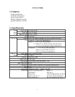
Page 2: ...0 1Vp p PAL SECAM burst signal 75Ω termination Component Y 1 0 0 1Vp p 75Ω termination CB PB 0 7 0 1Vp p 75Ω termination CR PR 0 7 0 1Vp p 75Ω termination RGB input output Analog RGB 0 7Vp p 75Ω termination Sync TTL level Audio Input 200mVrms 50KΩ Speaker output 1 0W mono Power supply 100 120VAC 2 6A 220 240VAC 1 4A Power consumption 240W Dimensions 332 W 92 H 254 D mm No including protruding part...

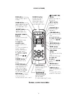
Page 3: ... from a video equipment Power switch RGB IN port Projector Rear Left STANDBY ON INPUT POWER LAMP TEMP MENU POWER indicator tells the state of power supply Refer to the section Power ON OFF INPUT button toggles between the signal ports MENU buttons operate the menu function STANDBY ON button prepares for turning the power on off Refer to the section Power ON OFF TEMP indicator lights or blinks when...

Page 4: ...FY ON OFF buttons turns on off the MAGNIFY mode In the MAGNIFY mode To move the magnified area 1 Press the POSITION button 2 Use the cursor buttons to move the picture 3 Press the POSITION button again to finish To shift the magnify level use the cursor buttons FREEZE button freezes reactivates the picture POSITION button turns on off the POSITION mode for RGB input In the POSITION mode To move th...

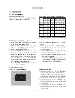
Page 5: ...image with more than 1m 40 type in diagonal size 3 Normalising the video adjustment Press the MENU button of the Remote control transmitter to display the MAIN menu After pressing the key use the or key to select RESET Next open MAIN menu and press the key to display the PICTURE1 menu Choose RESET and perfom EXECUTE by the same operation described above note The MAIN and PICTURE1 menu is not reset...

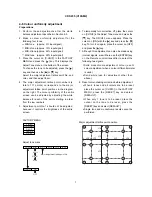
Page 6: ...al stripe adjustment Signals for internal adjustment 64 255 88 255 112 255 136 255 160 255 160 255 136 255 112 255 88 255 64 255 Adjustment procedure 1 Either of adjustment patterns as shown on the left appears which depends on the firmware version If any other pattern is displayed press the ENTER key on the remote control 2 Use the DAC P NRSH R in the FACTORY MENU to adjust so that the vertical s...

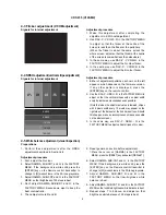
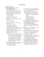
Page 7: ... the points starting in order from the low numbers 5 Adjustment point No 1 should not be adjusted because it controls the brightness of the entire screen 6 To temporarily turn correction off place the cursor on C UNIF in the Adjust Tone menu and press the key The ON OFF menu appears Place the cursor on ON with the key and press the key To turn it on again place the cursor on OFF and press the key ...

Page 8: ...2 R and B so that the co ordinates are as follows x x1 0 005 y y1 0 010 9 Similarly measure adjustment points No 3 to No 17 and adjust their colour co ordinates starting in order from the small number points This completes adjustments required for MIN Note Since excessive correction may lead to a correction data overview during internal calculations use the following values for reference No 2 to N...

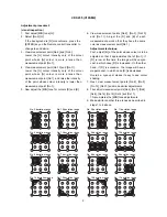
Page 9: ... cast makes it easy to see colour shading 7 Next view measurement points No 4 No 5 No 12 No 13 and make similar adjustments 8 Then adjust measurement points No 6 No 7 No 8 No 9 No 14 No 15 No 16 and No 17 This completes the MIN tone adjustments 9 Make similar another three tones as described in steps 1 to 8 above 8 3 16 17 9 11 6 14 2 12 15 13 10 7 4 1 5 8 3 16 17 9 11 14 12 15 13 10 4 1 5 6 2 7 8...

Page 10: ...ent program runs automatically 3 After the massage of END is displayed check the Offset value displayed according to the following spec Spec 150 Offset 227 4 If out of spec confirm the below conditions Then retry the same adjustment Description a Installing the air filter correctly b No obstruction and dust on air filter If not good condition clean or replace the air filter c Using the proper type...

Page 11: ...oints TSW MAIN Board E801 E803 E301 E800 D841 C P701 E804 E802 ET01 E805 E302 E7A1 ESPL P501 P601 D303 LAMP D301 POWER D302 TEMP S301 P ON S302 INP EA01 EV01 E102 E103 ET01 EM01 CNCT E101 SENSOR Board Rear view CONTROL Board REMC Board 6430 6800 ...

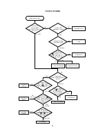
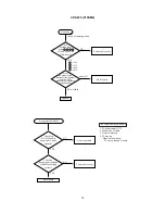
Page 12: ...sconnect TSW form Power unit circuit And check TSW short or open MAIN board Short TSW Open What is the state of TEMP indicator D302 No light DC FAN Blinks Jump to on the page 13 What is the state of LAMP indicator D303 No light Blinks 1 1 3 5 7 3 5 7 H More than 12 6V Measure voltage at the of E803 on the MAIN board L OV Limit SW board MAIN board Is the LAMP DOOR set OK Set the LAMP DOOR NG 2 ...

Page 13: ...302 No light Blinks DC FAN Lamp H 3 3V L 0V L OV 1 Is the voltage at the of E804 on the MAIN board fixed to L during warming up L 0V Measure sure voltage at the cathode pin of D841 on the MAIN board DC FAN Panel YES Normal Does the signal at the pin of E801 have a amplitude of 3 3V and a frequency of 40Hz or more MAIN board Thermistor A 6430 Infinity about 10k Measure the resistance of external ai...

Page 14: ...t NO YES Are voltage input at pins of E800 on the MAIN board 1 3 5 7 1 3 5 7 12V 17V 6 6V 4 1V Power unit circuit NO YES Are voltage input at pins of E800 on the MAIN board 12V 17V 6 6V 4 1V MAIN board LCD module assembly Check at operating mode 7 1 3 5 Picture is not displayed when the VIDEO S VIDEO Component Signal is input 7 1 3 5 ...

Page 15: ...asure the resistance of the Speaker 12V 17V 6 6V 4 1V 7 1 3 5 about 8 0 or infinity The check after parts change 1 PC power supply OFF 2 Connection of cable 3 Projector starting 4 PC starting When not operating PC set up change of cable No control to RS 232C MAIN board NO YES NO YES Use cross cable Check the RS 232C cable Are pin No 2 and 3 crossed Power unit circuit Check the power supply voltage...

Page 16: ... in the leaded solder thoroughly after the lead free solder has been completely melted do not apply the soldering iron without solder Servicing soldering iron A soldering iron with a temperature setting capability temperature control function is recommended The melting point of lead free solder is higher than leaded solder Use a soldering iron that maintains a high stable temperature large heat ca...

Page 17: ...hing or when opening a intake LID or when closing please carry out carefully and slowly so that load is not added to FPC cable MAIN Board 4 screws 2 Remove 2 screw 2 screw AC IN 3 Lift the rear of the MAIN board to the front 6 3 Cautions when removing the power unit BALLAST When removing the cable CNBAR connected to Power Unit BALLAST there is danger of damaging the small PCB connecting cables REA...

Page 18: ...ows Work in a relatively clean room so as to remove additional dust while in removal operation 1 Swab for cleaning P NX08061 Cotton stick L147 2 Air duster Dust blower spray can 3 Vacuum cleaner 2 Disassemble and open the maintenance hole 1 Turn off the projector and unplug the power cord 2 Remove the top cover according to the disassembling diagram of chapter 8 3 Remove the MAIN board according t...

Page 19: ...st While cleaning you can check the dust on screen While removing the dust separated dust will be blown off by air cooling system Please pay attention not to damage panel and filters 5 Re assembly 1 Turn off the set and remove the MAIN board 2 Set the intake LID 3 Re assemble the MAIN board 4 Re assemble the set 5 While re assembling clean the intake LID and intake filter and filter cover using a ...

Page 20: ...o not mix new batteries with used ones When inserting batteries verify that the plus and minus terminals are aligned correctly as indicated in the remote control When you dispose the battery you should obey the law in the relative area or country 1 Remove the battery cover Slide back and remove the cover in the direction of the arrow 2 Insert the batteries Align and insert the two AA batteries acc...

Page 21: ...owing Reset The Filter Timer 1 Turn on the projector While the projector running press the MENU button to open the menu 2 Choose the OPTION on the menu using the button then press the button or ENTER button 3 Choose the FILTER TIME using the button then press and hold the button of projector or the RESET button of remote control for 3 seconds 4 Choose the RESET using the button Replacing the air f...

Page 22: ...jector vents or get it in your eyes or mouth Before replacing the lamp make sure the power switch is off and the power cable is not plugged in then wait at least 45 minutes for the lamp to cool sufficiently Handling the lamp while hot can cause burns as well as damaging the lamp Do not open the lamp cover while the projector is suspended from above This is dangerous since if the lamp s bulb has br...

Page 23: ...t the bottom is facing up 3 Hold the release button while sliding and taking the lamp cover up 4 Unscrew the 2 screws and slowly pick up the lamp by the handles 5 Insert the new lamp and tighten the 2 screws firmly to lock it in place 6 Slide the lamp cover into place until it locks into position 7 Slowly turn the projector so that the top is facing up 8 Turn on the projector and reset the lamp ti...

Page 24: ...ignal processing To avoid such phenomena AUTO function should be used with the full size picture that has bright tone on its peripheral NOTE The phenomenon at the failure of AUTO adjustment depends on resolution of input source scene of picture etc There is no failure above in AUTO with video source through VIDEO S VIDEO or COMPONENT input The reason is why recognition of input signal s standard d...

Page 25: ... the button 3rd entry code Press the KEYSTONE button 4th entry code Press the button Note The Master PIN codes can be used up to 30 times The codes cannot be used thereafter If the Master PIN codes cannot be used see the following paragraph The PIN LOCK System inactivation 1 When the PIN BOX menu is displayed press RESET for 3 seconds or more in order to get the ID Inquiring Code PIN BOX ID Inquir...

Page 26: ...EAN THE AIR FILTER AFTER CLEANING THE AIR FILTER RESET THE FILTER TIMER A note of precaution when cleaning the air filter Please immediately turn the power OFF and clean or change the air filter by referring to the Air Filter section of this manual After you have cleaned or changed the air filter please be sure to reset the filter timer If the same message is displayed after the treatment please c...

Page 27: ... following items and then turn the power ON again If the same indication is displayed please change the lamp Is there blockage of the air passage aperture Is the air filter is dirty Does the peripheral temperature exceed 35 C Lights or blinks in red Blinks in red Turned off The lamp cover has not been properly fixed attached Turn the power OFF and wait at least 45 minutes After the unit has suffic...

Page 28: ...hen press the button together with INPUT and hold for 3 seconds 1 Display the menu by the MENU button 2 Select the OPTION on the menu 3 Press the MAGNIFY OFF button Next hold the MAGNIFY OFF button for 3 seconds 2 Select the HIGH on the OSD using the button To reset this setup select the NORMAL using the button 3 The OSD will be ended by no operation for 10 seconds or change of input signal To end...

Page 29: ...except buttons Set operating time display method accumulated lamp time display method 1 Select Option from the Menu display then select Lamp Time 2 Press the Reset button once then press Keystone for 3 seconds or more to display the screen shown below The menu will close after 10 seconds if there are no further operations 3 Use or to select the usage status number The usage status is as shown belo...

Page 30: ...he FEB9 that was installed in the CNCT with a Z3 band and cut off any excess length Then Wiring the CNCT into the FEB9 brings near to the notch in the Control board and Z3 should be fixed directly to FEB9 Install the FEB9 ferrite core in the CNCT Wind the CNCT three times around the FEB9 making sure that it passes through it four times CNBAR CN200 Confirm that CN200 is connected properly confirmat...

Page 31: ...off Lock CNPWR completely when connecting the connector to ballast power CN100 Arrange the lead as shown and attach FEB2 close to the circuit power Do not wedge in cooling wheel or igniter transformer Assembly procedure 1 Pass CNBAR through ballast power block fastener and lock 2 Pass CN1 and CD2 through circuit power block fastener and lock 3 Connect one end of CNPWR to ballast power 4 Pass lamp ...

Page 32: ... not touch this 6430 A83 FEBA Z4 Secure ZTP4 and ZTP5 with tape to prevent 6460 connector lead from overlapping A83 6800 CNRM 6460 ZTP5 ZTP4 Pass wire between PBS duct and optical unit After fastening down the FEBA to the Z4 on the ribs of the bottom case cut off any excess length Pass the A83 leads twice through the FEBA Arrange speaker and internal air sensor leads as shown below Extract the spe...

Page 33: ... integration wiring Power block integration 1 Connect CN1 2 Secure FG CD2 and CNSH to power block with screw 3 Connect and wire lamp lead Confirm that lamp lead is embedded properly into rib on underside of bottom case Confirm same for erect part Ensure erect part of lead does not protrude from rib To prevent lead getting caught between duct and rib Run CNSH through FEB5 four times and then clamp ...

Page 34: ...6800 6430 CNRM CNME 3055 and CNSH connectors 3 Connect LCD panel cable Arrange 6460 lead eliminating slack and secure with fastener located on top of power block to prevent interference with projection lense Connector base Insert flexible cable into connector base properly Confirm cable facing correct direction as connector is top contact type Move lock hinge in direction of arrow and lock properl...

Page 35: ...ing screw 6 5 6 2 1 Dichroic optics unit Power supply unit LCD Lens prism 21 19 Lamp fan duct 28 20 27 22 3 M3x10 T3x12 T3x16 M3x6 lock M4x8 T3x12 T3x12 Notice 4 10 Notice 5 18 T2x5 T3x12 T3x12 T3x12 Notice 3 Notice 1 8 T3x12 black 26 25 4 M3x10 9 12 7 T3x12 black ...

Page 36: ...rew T Tapping screw 24 16 16 14 29 30 17 13 15 Dichroic optics unit LCD Lens prism Lamp fan duct MAIN Board Power supply unit 23 11 31 M3x8 black M3x8 black M3x8 M3x8 M3x30 T3x35 M3x6 M3x10 M3x10 T3x8 T3x35 M3x30 M3x30 M3x6 Notice 2 ...

Page 37: ...se as shown below when attaching or dismantling upper case Notice a b c d e 4 Align shield case joints 5 Attach lamp case bracket as shown below after removing dichroic optics unit and duct assembly Ԙ ԙ Ԛ Insert in direction then swivel in direction Ԙ ԙ Precautions Swivel case to avoid applying pressure to projection lens when mounting Same applies to REMC board and sensor board Insert while pulli...

Page 38: ...38 CP S235 C10SM2 9 Replacement Parts list Power cord RGB cable Remote control THE UPDATED PARTS LIST FOR THIS MODEL IS AVAILABLE ON ESTA ...

Page 39: ...4 5 6 7 8 9 CD RD TD DTR GND DSR RTS DTS RI Projector RS 232C cross cable Computer 9 8 7 6 1 2 3 4 5 6 7 8 9 5 4 3 2 1 6 7 8 9 5 4 3 2 1 9 8 7 6 1 2 3 4 5 Communications setting 19200bps 8N1 1 Protocol Consist of header 7 bytes command data 6 bytes 2 Header BE EF 03 06 00 CRC_low CRC_high CRC_low Lower byte of CRC flag for command data CRC_high Upper byte of CRC flag for command data 3 Command dat...

Page 40: ...ecrement command 1 The computer sends the decrement code Header Command data 05H 00H type 2 bytes 00H 00H to the projector 2 The projector decreases the setting value on the above setting code 3 The projector returns the response code 06H to the computer When the projector cannot understand the received command When the projector cannot understand the received command the error code 15H is sent ba...

Page 41: ...00 00 Decrement BE EF 03 06 00 4A D2 05 00 04 20 00 00 Contrast Reset Execute BE EF 03 06 00 A4 D2 06 00 01 70 00 00 Aspect Set 4 3 BE EF 03 06 00 9E D0 01 00 08 20 00 00 16 9 BE EF 03 06 00 0E D1 01 00 08 20 01 00 15 9 BE EF 03 06 00 6E D0 01 00 08 20 03 00 32 15 BE EF 03 06 00 5E D2 01 00 08 20 04 00 WIDE BE EF 03 06 00 CE D3 01 00 08 20 05 00 ZOOM BE EF 03 06 00 3E D3 01 00 08 20 06 00 Get BE E...

Page 42: ...3 06 00 A7 F1 01 00 A1 30 02 00 CUSTOM BE EF 03 06 00 07 FD 01 00 A1 30 10 00 Get BE EF 03 06 00 F4 F0 02 00 A1 30 00 00 Custom Gamma Get BE EF 03 06 00 08 F1 02 00 A0 30 00 00 Increment BE EF 03 06 00 6E F1 04 00 A0 30 00 00 Decrement BE EF 03 06 00 BF F0 05 00 A0 30 00 00 Custom Colour Temp Set USER BE EF 03 06 00 3B F8 01 00 B0 30 10 00 HIGH BE EF 03 06 00 0B F5 01 00 B0 30 03 00 MIDDLE BE EF 0...

Page 43: ...6 00 23 D2 04 00 06 20 00 00 Decrement BE EF 03 06 00 F2 D3 05 00 06 20 00 00 Colour Balance B Reset Execute BE EF 03 06 00 D0 D3 06 00 06 70 00 00 Sharpness Get BE EF 03 06 00 F1 72 02 00 01 22 00 00 Increment BE EF 03 06 00 97 72 04 00 01 22 00 00 Decrement BE EF 03 06 00 46 73 05 00 01 22 00 00 Sharpness Reset Execute BE EF 03 06 00 C4 D0 06 00 09 70 00 00 Colour Get BE EF 03 06 00 B5 72 02 00 ...

Page 44: ...ver Scan Reset Execute BE EF 03 06 00 EC D9 06 00 27 70 00 00 Colour Space Set AUTO BE EF 03 06 00 0E 72 01 00 04 22 00 00 RGB BE EF 03 06 00 9E 73 01 00 04 22 01 00 SMPTE240 BE EF 03 06 00 6E 73 01 00 04 22 02 00 REC709 BE EF 03 06 00 FE 72 01 00 04 22 03 00 REC601 BE EF 03 06 00 CE 70 01 00 04 22 04 00 Get BE EF 03 06 00 3D 72 02 00 04 22 00 00 Component Set COMPONENT BE EF 03 06 00 4A D7 01 00 ...

Page 45: ...Get BE EF 03 06 00 85 D6 02 00 16 20 00 00 Blank Colour Set Blue BE EF 03 06 00 CB D3 01 00 00 30 03 00 White BE EF 03 06 00 6B D0 01 00 00 30 05 00 Black BE EF 03 06 00 9B D0 01 00 00 30 06 00 Get BE EF 03 06 00 08 D3 02 00 00 30 00 00 Blank on off Set TURN OFF BE EF 03 06 00 FB D8 01 00 20 30 00 00 TURN ON BE EF 03 06 00 6B D9 01 00 20 30 01 00 Get BE EF 03 06 00 C8 D8 02 00 20 30 00 00 Startup ...

Page 46: ...8 C6 06 00 40 70 00 00 Magnify Get BE EF 03 06 00 7C D2 02 00 07 30 00 00 Increment BE EF 03 06 00 1A D2 04 00 07 30 00 00 Decrement BE EF 03 06 00 CB D3 05 00 07 30 00 00 Freeze Set Normal BE EF 03 06 00 83 D2 01 00 02 30 00 00 Freeze BE EF 03 06 00 13 D3 01 00 02 30 01 00 Get BE EF 03 06 00 B0 D2 02 00 02 30 00 00 Power Set TURN OFF BE EF 03 06 00 2A D3 01 00 00 60 00 00 TURN ON BE EF 03 06 00 B...

Page 47: ...udio Video OPTICAL UNIT PROJECTION LENS FAN Lamp EEPROM Crystal A D PLL THC7216 S Video S P COLOUR UNIFORMITY TIMING GENERATOR AUDIO AMP VIDEO DECODER TC90A92AFG Video Audio SELECTOR CONTROL PCB RGB out DDC PW168 05RK Image Processor VOLUME CONTROL RS 232C 1st PLL RGB A D 6dB AMP Audio out CTL S H LEVEL SHIFTER KEY TEMP SENSOR STUCK SENSOR SUB CPU SEL COMP USB MOUSE SW PCB IR RECEIVER PCB SENSOR P...

Page 48: ...7 LCCOM 28 DIRY 28 DIRY 29 VSSY 29 VSSY 30 MON 30 MON LCD Panel Cover SW Board 1 LAMP TEMP DET OUT 2 LAMP TEMP DET RETURN 1 TO SW 2 COVER Panel fan 1 FAN2S 2 VCC 3 GND 4 CONT P 1 OUT 2 GND Y IN Pb Cb IN Pr Cr IN AUDIO R IN CNBAR 4P ZH 160mm P EF23002 CN102 ESPL E804 With Ballast Power Unit CNPWR 4P VH 130mm P EF22877 CNPOW 12P PH 190mm P EF21953 A83 2P DF13 90mm SP Assy P GK00393 J1 J2 E800 1 FAN1...

Page 49: ...EMOTE CONTROL Board FILTER UNIT POWER UNIT CIRCUIT POWER UNIT BALLAST 1 POWER UNIT BALLAST 2 CONTROL Board MAIN Board 1 MAIN Board 2 MAIN Board 3 MAIN Board 4 MAIN Board 5 MAIN Board 6 MAIN Board 7 MAIN Board 8 MAIN Board 9 MAIN Board 10 MAIN Board 11 Basic circuit diagram list ...

Page 50: ...SM0541 SENSOR COVER SWITCH REMOTE CONTROL BOARDS COVER SWITCH BOARD REMOTE CONTROL BOARD SENSOR BOARD PARTS WITH HATCHING ARE NOT MOUNTED ...

Page 51: ...SM0541 POWER UNIT CIRCUIT FILTER UNIT PARTS WITH HATCHING ARE NOT MOUNTED POWER UNIT CIRCUIT FILTER UNIT ...

Page 52: ... NAV1 7 NAV2 9 CPO 16V CN100 1 CN100 2 CN100 3 CN100 4 L100 L104 R100 R101 R102 R103 C100 R104 C140 C152 R160 R113 R112 Q150 Q151 C151 C133 R151 D151 D105 C108 ZD100 L102 D106 C153 C154 R161 R145 C130 TH101 TH102 R114 R140 R141 R133 C109 R142 R143 R134 R115 R116 C122 R117 R135 C131 C110 R123 D107 D121 R156 R118 D115 R125 C155 D116 R127 C112 R126 R121 R122 C111 Z100 T102 C120 Q101 C114 Q104 C116 Q1...

Page 53: ...SM0541 POWER UNIT BALLAST 2 PARTS WITH HATCHING ARE NOT MOUNTED ...

Page 54: ...SM0541 CONTROL BOARD PARTS WITH HATCHING ARE NOT MOUNTED ...

Page 55: ...SM0541 MAIN BOARD 1 PARTS WITH HATCHING ARE NOT MOUNTED ...

Page 56: ...SM0541 MAIN BOARD 2 PARTS WITH HATCHING ARE NOT MOUNTED ...

Page 57: ...SM0541 MAIN BOARD 3 PARTS WITH HATCHING ARE NOT MOUNTED ...

Page 58: ...SM0541 MAIN BOARD 4 PARTS WITH HATCHING ARE NOT MOUNTED ...

Page 59: ...SM0541 MAIN BOARD 5 PARTS WITH HATCHING ARE NOT MOUNTED ...

Page 60: ...SM0541 MAIN BOARD 6 PARTS WITH HATCHING ARE NOT MOUNTED ...

Page 61: ...SM0541 MAIN BOARD 7 PARTS WITH HATCHING ARE NOT MOUNTED ...

Page 62: ...SM0541 MAIN BOARD 8 PARTS WITH HATCHING ARE NOT MOUNTED ...

Page 63: ...SM0541 MAIN BOARD 9 PARTS WITH HATCHING ARE NOT MOUNTED ...

Page 64: ...SM0541 MAIN BOARD 10 PARTS WITH HATCHING ARE NOT MOUNTED ...

Page 65: ...SM0541 MAIN BOARD 11 PARTS WITH HATCHING ARE NOT MOUNTED ...

Page 66: ...47 Milano Italia ITALY Tel 39 02 487861 Tel 39 02 38073415 Servizio Clienti Fax 39 02 48786381 2 Email customerservice italy hitachi eu com HITACHI Europe AB Box 77 S 164 94 Kista SWEDEN Tel 46 0 8 562 711 00 Fax 46 0 8 562 711 13 Email csgswe hitachi eu com HITACHI EUROPE S A S Lyon Office B P 45 69671 BRON CEDEX FRANCE Tel 04 72 14 29 70 Fax 04 72 14 29 99 Email france consommateur hitachi eu co...

Reviews: