background image


HP-313 

July 2009 

Model: HRT1 


Flow Rate Indicator/Totalizer With

HART

 Communications Protocol


USER’S MANUAL 


HP-313  

April 2018 

107 Kitty Hawk Lane 

P.O. Box 2145 

Elizabeth City, NC 27909

1-800-628-4584 

 (252) 331-1997 

 Fax (252) 331-2886 

www.hofferflow.com              email:  info@hofferflow.com 

Summary of Contents for HRT1

Page 1: ...te Indicator Totalizer With HART Communications Protocol USER S MANUAL HP 313 April 2018 107 Kitty Hawk Lane P O Box 2145 Elizabeth City NC 27909 1 800 628 4584 252 331 1997 Fax 252 331 2886 www hoffe...

Page 2: ......

Page 3: ......

Page 4: ......

Page 5: ...nual before connecting it to the system In many cases a system wiring drawing is available and may be requested from Hoffer Flow Controls This document contains proprietary information which is protec...

Page 6: ...horization RMA Number from HFC s Customer Service Department within 30 days after discovery of a purported breach of warranty but not later than the warranty period otherwise such claims shall be deem...

Page 7: ...ng Summary 18 4 CONFIGURATION 19 4 1 Local Configuration 19 4 2 Default Configuration 22 5 OPERATION AND MAINTENANCE 23 5 1 Display Parameters 23 5 2 Saving Grand Total 23 5 3 Clearing the Total 23 5...

Page 8: ...HP 313 HRT1 APPENDIX A DEFAULT CONFIGURATION 43 APPENDIX B Declaration and Conformity 45 APPENDIX C Installation Drawings and Conditions for Safe Use for Certified Systems 47...

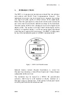
Page 9: ...uid crystal display LCD The top line is an 8 digit Total Volume display and the bottom is a 5 digit Rate display A 4 20 mA analog signal proportional to the flowrate is output on the current loop The...

Page 10: ...Standard EN 61000 6 3 Residential Commercial Light Industry Environment Generic Immunity Standard EN 61000 6 1 Residential Commercial Light Industry Environment Electrostatic discharge requirements E...

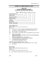
Page 11: ...ER COATED ENCLOSURE IP66 P PANEL MOUNT ENCLOSURE IP40 PD PANEL MOUNT ENCLOSURE WITH CLEAR DOOR AND LOCK IP40 4 NEMA 1 ENCLOSURE HRT1 MOUNTED TO THE OUTSIDE OF CLEAR COVER FOR DOOR DRY INSTALLATION ONL...

Page 12: ...A 4X STYLE 2 ENCLOSURE MOUNTED ON TURBINE MUST BE USED WITH X RISER TURBINE OPTION FHT 8 LONG TEMPERATURE RISER FOR NEMA 4X STYLE 2 ENCLOSURES MOUNTED ON TURBINE REQUIRED WHEN FLUID TEMPERATURES EXCEE...

Page 13: ...OPTIONS ___U1 OPTIONAL 1 MALE X 1 FEMALE EX PROOF UNION NOTE USE WITH MX AND RX OPTIONS ___U2 OPTIONAL 3 4 MALE X 3 4 FEMALE EX PROOF UNION NOTE USE WITH MA AND RA OPTIONS EXPLOSION PROOF ENCLOSURE RA...

Page 14: ...Introduction 6 HP 313 HRT1 This Page Intentionally Left Blank...

Page 15: ...tions Total Units GAL LIT FT3 M3 BBL blank Grand Total 8 digits 0 26 high non resettable Value stored once per minute in non volatile memory Grand Total is displayed for 15 seconds after pressing the...

Page 16: ...losure Frequency Range 0 Hz to 5000 Hz Signal Type Contact closure Sig Terminal to DC common Internal Pull up 220 k to 3 3 VDC Reset Signal Type Contact closure Reset Terminal to DC common Min On 25 m...

Page 17: ...upply Voltage Open collector 30 VDC 100 mA Divider 1 10 100 or OFF Rate Duration See below Frequency Hz 1 2 4 8 On Off msec 500 250 125 62 5 2 6 Alarm 1 and Alarm 2 Type 0 5V TTL 0 Supply Voltage Open...

Page 18: ...brane keypad Pulse Input supports turbine as well as many other pulse generating flowmeters Up to 20 Point Linearization to correct for flowmeter non linearities 4 20 mA analog output proportional to...

Page 19: ...the HRT1 2 option NEMA 4X front panel mounted behind the clear cover 1 Loosen the four cover screws and remove the clear cover 2 Remove the four 4 40 x 5 16 black oxide screws from the corners of the...

Page 20: ...follow the steps below to avoid twisting signal wires from pickup coil 1 Remove the HRT1 electronics from the enclosure 2 Disconnect the signal wires from the HRT1 electronics if connected 3 Mount Thr...

Page 21: ...ded as a backup power supply to ensure that volume accumulation will not be interrupted during a power failure Switch 2 of SW 2 must be ON for loop power Figure 3 1 1 4 20mA Loop Wiring and Switch Set...

Page 22: ...ust be set according to the type of flowmeter input to be used Proper switch settings will be made at the factory if the flowmeter input is specified at the time of order SW 2 SWITCH SETTINGS FOR FLOW...

Page 23: ...IG IN B A Redi Pulse Pickup C Figure 3 2 2 Isolated Redi Pulse TTL Wiring and Switch Settings Isolated Redi Pulse Open Collector Requires 3 Wire Installation POWER SUPPLY 8 30 VDC JP2 6 3 1 8 TB2 TB1...

Page 24: ...aled so that the pulse frequency does not exceed the Pulse Frequency setting 8 Hz Max at the maximum flow rate The Pulse Output may be configured as an Open Collector 0 5V TTL or Internal pullup to VD...

Page 25: ...ALARM2 TS2 OPEN COLLECTOR 4 OFF 36V TRANSORB 5 OFF 36V TRANSORB TTL 4ON 5 1V ZENER 5 ON 5 1V ZENER PULLUP TO VDC 4 ON 36V TRANSORB 5 ON 36V TRANSORB Figure 3 4 1 Alarm Outputs Circuit Overview JP2 6 3...

Page 26: ...nd output signals The shield should be connected to the chassis ground lug on the HRT1 The shield on the opposite end of the cable should be left open This wiring practice is mandatory in order to com...

Page 27: ...e Display Option Menu item Description CLEArtot no Yes No Clear Total Clears accumulated total and sets TOTAL display to zero 10000000 tA9 Tag Number User defined 8 digit serial number AuErAgE FAC NN...

Page 28: ...s gal for each entry in the table 1 000 C FAC 0 001 to 99999 999 Correction Factor User defined number between 0 001 and 99999 999 to multiply flow and total Default 1 0 tot unit 100 100 GAL 110 FT3 1...

Page 29: ...E S oFF oFF 1 10 100 Pulse Scale Sets scale for pulse out 1 10 100 units of total for one pulse out Pulses are scaled according to the least significant digit of the displayed total For example if Tot...

Page 30: ...out rAtE rAtE 4 12 20 Current Out Sets analog output to follow rate or a predefined level for loop diagnostics PuL test no Yes No Pulse Output Test Outputs a test frequency of 1Hz 50 duty cycle AL 1...

Page 31: ...sentation of the flow rate based on a percentage of the maximum flow setting The flow rate and flow total are calculated and updated on the display once every 2 seconds 5 2 Saving Grand Total To minim...

Page 32: ...e between 3 and 12 seconds depending on the Max Sample Time setting MST Changing the MST is only recommended for low flow applications where the input frequency is below 1 Hz See Chapter 4 Configurati...

Page 33: ...w rate or reduce the number of places after the flow rate decimal point EFLo Flow rate exceeds the 20 mA max flow setting Analog output will saturate at 24 mA Reduce flow rate or increase the 20 mA ma...

Page 34: ...Operation and Maintenance 26 HP 313 HRT1 This Page Intentionally Left Blank...

Page 35: ...the HRT1 Main Board PCA186 Refer to Chapter 3 Installation for information on connections to HART devices HART functions are defined as part of an enhanced device description language EDDL Contact th...

Page 36: ...Unique Identifier with Tag 12 Read Message 13 Read Tag Descriptor Date 14 Read Primary Variable Sensor Info 15 Read Primary Variable Output Info 16 Read Final Assembly Number 17 Write Message 18 Writ...

Page 37: ...ead the flowmeter linearization parameters 134 Write Linearization Set flowmeter linearization method as Average K Factor or Linearization Table 135 Write K Factor Decimal Point Select k factor resolu...

Page 38: ...for Alarm 1 and 2 148 Write Alarm Function Define the function of the Alarm Output as Rate or Total 149 Write Alarm Level Write the value at which an alarm condition is indicated 150 Alarm Release Rel...

Page 39: ...or flow rate time base Sec Min Hr Day 163 Write Total Units Write units for volume total GAL FT3 L M3 BBL 6 5 Device Status The following Status Bits are implemented Bit 0 Primary Variable Out Of Limi...

Page 40: ...igh 5 DAC Zero Not Calibrated 6 DAC Gain Not Calibrated 0 7 Bit Current Override 0 Total Units Error 1 Rate Time Units Error 2 Linearization Function Error 3 K Factor Decimal Point Error 4 Number of P...

Page 41: ...Alarm 2 Test 3 7 Alarm 1 Test 0 Unused 1 Unused 2 Unused 3 Unused 4 Unused 5 Unused 6 Alarm 2 Activated 4 7 Alarm 1 Activated 0 Unused 1 Unused 2 Unused 3 Unused 4 Unused 5 Unused 6 Unused 5 7 Unused...

Page 42: ...Unused 2 Unused 3 Unused 4 Unused 5 Unused 6 Unused 7 7 Unused 0 Simulation Active 1 Non Volatile Memory Defect 2 Volatile Memory Defect 3 Watchdog Reset Executed 4 Voltage Conditions Out of Range 5...

Page 43: ...w setting Flow Rate URV Display of Upper Range Value for 20 mA flow setting Total Display of currently measured volumetric flow total with units selected Grand Total Display of currently measured gran...

Page 44: ...libration Flow rate exceeds the 20 mA flow rate upper range value URV Analog output will saturate at 24 mA Displayed as EFLo on the HRT1 LCD display See section 5 5 Error Conditions for more informati...

Page 45: ...otal Setup Clear Total Select YES to clear Total Grand Total is non resettable Set Total Write a specific value to Total Units Select L M3 GAL BBL FT3 OR BLANK custom for Total units Total Decimal Poi...

Page 46: ...Set analog output to fixed mode by selecting 4 mA 20 mA or OTHER Alarm 1 Alarm 1 Function Select TOTAL RATE or OFF Alarm 1 Out Numeric entry to assign an alarm threshold Set Alarm 1 ON Toggle Alarm 1...

Page 47: ...oint in table Average K Factor Enter Average K Factor when AVERAGE K FACTOR is selected for Linearization Correction Factor User defined flow total multiplier between 0 001 and 99999 999 HART Setup Po...

Page 48: ...HART Communications 40 HP 313 HRT1 This Page Intentionally Left Blank...

Page 49: ...ument is in a well ventilated area before opening the enclosure to avoid breathing fumes trapped inside the enclosure Exercise caution in handling and disposing of spent or damaged batteries Important...

Page 50: ...or wiring is inside the enclosure 8 Replace the enclosure cover threading it onto the enclosure in a clockwise direction NEMA Enclosure 1 Loosen by turning counter clockwise the screws in each corner...

Page 51: ...9 985 FREQUENCY 06 4999 986 FREQUENCY 07 4999 987 FREQUENCY 08 4999 988 FREQUENCY 09 4999 989 FREQUENCY 10 4999 990 FREQUENCY 11 4999 991 FREQUENCY 12 4999 992 FREQUENCY 13 4999 993 FREQUENCY 14 4999...

Page 52: ...9 1 00 K FACTOR 20 1 00 CORRECTION FACTOR 1 000 TOTAL UNITS 100 GAL RATE UNITS MINUTES MAX SAMPLE TIME 01 OUT LOW LRV 4MA 00000 000 OUT HIGH URV 20 MA 99 999 PULSE SCALE 0 OFF PULSE FREQENCY 8 ALARM 1...

Page 53: ...Appendix B Declaration of Conformity 45 HRT1 HP 313 APPENDIX B Declaration of Conformity...

Page 54: ...Appendix B Declaration of Conformity 46 HP 313 HRT1...

Page 55: ...Appendix C Installation Drawings and Conditions 47 for Safe Use for Certified Systems HRT1 HP 313 APPENDIX C Installation Drawings and Conditions for Safe Use for Certified Systems...

Page 56: ...48 Appendix C Installation Drawings and Conditions for Safe Use for Certified Systems HP 313 HRT1...

Page 57: ...Appendix C Installation Drawings and Conditions 49 for Safe Use for Certified Systems HRT1 HP 313...

Page 58: ...50 Appendix C Installation Drawings and Conditions for Safe Use for Certified Systems HP 313 HRT1...

Page 59: ...Appendix C Installation Drawings and Conditions 51 for Safe Use for Certified Systems HRT1 HP 313...

Page 60: ...52 Appendix C Installation Drawings and Conditions for Safe Use for Certified Systems HP 313 HRT1...

Page 61: ...Appendix C Installation Drawings and Conditions 53 for Safe Use for Certified Systems HRT1 HP 313...

Page 62: ...54 Appendix C Installation Drawings and Conditions for Safe Use for Certified Systems HP 313 HRT1...

Page 63: ...Appendix C Installation Drawings and Conditions 55 for Safe Use for Certified Systems HRT1 HP 313...

Page 64: ...56 Appendix C Installation Drawings and Conditions for Safe Use for Certified Systems HP 313 HRT1...

Page 65: ...Appendix C Installation Drawings and Conditions 57 for Safe Use for Certified Systems HRT1 HP 313...

Page 66: ...58 Appendix C Installation Drawings and Conditions for Safe Use for Certified Systems HP 313 HRT1...

Page 67: ...Appendix C Installation Drawings and Conditions 59 for Safe Use for Certified Systems HRT1 HP 313...

Reviews: