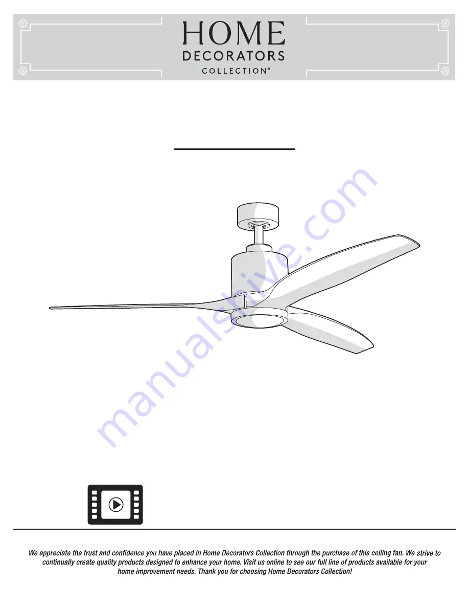
background image


USE AND CARE GUIDE

TRIPLEX 60 IN. CEILING FAN


Item #1003 823 860

#1003 823 861

#1003 823 859

Model #YG749-BN

 #YG749-BRB

 #YG749-PN


THANK YOU

THANK YOU

Questions, problems, missing parts? Before returning to the store,  

call Home Decorators Collection Customer Service 

8 a.m. - 7 p.m., EST, Monday-Friday, 9 a.m. - 6 p.m., EST Saturday 

1-800-986-3460

HOMEDEPOT.COM/HOMEDECORATORS

Visual instruction of how to install this fan:
Visit www.homedepot.com and enter either the Item or Model number to find 
this fan and click the link of visual instruction in the product overview section.

Summary of Contents for 1003 823 859

Page 1: ...efore returning to the store call Home Decorators Collection Customer Service 8 a m 7 p m EST Monday Friday 9 a m 6 p m EST Saturday 1 800 986 3460 HOMEDEPOT COM HOMEDECORATORS Visual instruction of how to install this fan Visit www homedepot com and enter either the Item or Model number to find this fan and click the link of visual instruction in the product overview section ...

Page 2: ... 16 18 19 20 20 22 Table of Contents 2 Table of Contents Safety Information Warranty Pre Installation Tools Required Hardware Included Package Contents Dual Mounting Instructions Installation Assembly Standard Ceiling Mounting Close to Ceiling Mounting Hanging the Fan Attaching the Fan Blades Installing the Light Kit 2 3 4 4 4 4 5 6 7 8 9 9 10 11 14 15 READ AND SAVE THESE INSTRUCTIONS ...

Page 3: ...t grounding conductor on one side of the outlet box and ungrounded conductor on the other side of the outlet box 9 All setscrews must be checked and retightened where necessary before installation 10 Suitable for use with solid state speed control RH786NRW only 11 This device complies with part 15 of the FCC Rules Operation is subject to the following two conditions 1 This device may not cause har...

Page 4: ...xing any accessories is not covered by this warranty Because of varying climatic conditions this warranty does not cover any changes in brass finish including rusting pitting corroding tarnishing or peeling Brass finishes of this type give the longest useful life when protected from varying weather conditions A certain amount of wobble is normal and should not be considered a defect Servicing perf...

Page 5: ...pin preassembled Cotter pin preassembled Cross pin preassembled Setscrew preassembled Collar setscrew preassembled Collar mounting screw with lock washer preassembled Light kit mounting plate screw preassembled Light kit mounting screw preassembled 1 5V AAA battery Part Part Description Description 3 4 7 1 1 1 1 2 6 3 3 2 Quantity Quantity 5 HOMEDEPOT COM HOMEDECORATORS Please contact 1 800 986 34...

Page 6: ...otor assembly Blade Light kit mounting plate 14 watt LED Light kit Plastic shade Remote control Quantity Quantity 1 3 1 1 1 1 Part Part A B C D E F Quantity Quantity 1 1 1 1 1 1 Description Description Mounting bracket preassembled Canopy ring preassembled Canopy Canopy bottom cover preassembled Hanger ball downrod assembly Coupling cover ...

Page 7: ...dard downrod installation the distance from the ceiling to the bottom of the fan blades will be approximately 12 in The close to ceiling installation reduces the distance from the ceiling to the bottom of the fan blades to approximately 9 in Once you have decided which ceiling installation you will use refer to the corresponding sections and procedures during the assembly period Where necessary ea...

Page 8: ...hree different ways to mount the outlet box MM not included MM MM NN MM MM A Installation MOUNTING OPTIONS MOUNTING OPTIONS WARNING To reduce the risk of fire electric shock or personal injury mount the fan to an outlet box marked acceptable for fan support using the screws provided with the outlet box An outlet box commonly used for the support of lighting fixtures may not be acceptable for fan s...

Page 9: ...oosening and possibly falling B G F OO C PP RR QQ HH HH DD EE FF Carefully feed the motor wires and antenna wire RR up through the downrod QQ Thread the downrod QQ into the collar Align the holes and replace the clevis pin DD and cotter pin EE Tighten the two collar setscrews HH Slip the coupling cover F canopy ring B and canopy C onto the downrod QQ Carefully reinstall the hanger ball OO onto the...

Page 10: ...ting bracket A from the canopy C by loosening the four canopy mounting screws BB on the top of the canopy C Remove the two non slotted canopy mounting screws BB and loosen the slotted canopy mounting screws BB Remove the canopy bottom cover D from the canopy C Make sure the slot openings of the canopy ring B are on top and then proceed to place the canopy ring B and canopy C over the collar at the...

Page 11: ...ing system marked acceptable for fan support and use the mounting screws provided with the outlet box WARNING The tab in the ring must rest in the groove of the hanger ball E Failure to properly seat the tab in the groove could cause damage to the wiring WARNING The hook is only to hold the fan while attaching wiring Failure to hang as instructed may result in the tab breaking causing the fan to f...

Page 12: ...ledge or experience have your fan installed by a licensed electrician Follow the steps below to connect the fan to your household wiring Use the plastic wire nuts AA with your fan Secure the plastic wire nuts AA with electrical tape Make sure there are no loose strands or connections Make wire connections as follows using the wire nuts AA From Fan To Outlet Box Black Wire Black Wire Hot White Wire...

Page 13: ...firmly tightened Slide the canopy C up to the ceiling Make sure you have placed the wires safely into the outlet box MM Secure the canopy C to the mounting bracket A with the four canopy mounting screws with lock washers BB included with your fan Raise up canopy ring B and line up the four grooves with the four screw heads on the canopy C Once lined up slide the canopy ring B and secure it to the ...

Page 14: ...secure the blade in place with screws and washers CC provided Repeat this process to attach the other two blades H Assembly Attaching the Fan Blades 14 G CC H 8 Removing the rubber packing mounts The fan motor assembly G is shipped with rubber packing mounts SS to prevent movement during transportation Remove the six rubber packing mounts SS from the fan motor assembly G and discard prior to attac...

Page 15: ... light kit and plastic shade CAUTION Before starting installation disconnect the power by turning off the circuit breaker or removing the fuse at the fuse box Turning power off using the fan switch is not sufficient to prevent electric shock Remove the two light kit mounting screws KK from the light kit mounting plate I While holding the 14W LED light kit J under the fan motor assembly G make the ...

Page 16: ... Turn the fan s AC power ON Within 60 seconds of turning AC power on press and release the Pairing button located in the remote s battery compartment to enter the learning function Once the fan has detected the remote controls s frequency the down light of your fan if applicable will blink and the fan blades will start to spin The fan will now accept commands from the added remote LEARNING PROCESS...

Page 17: ...ment to the 0 position Turn the fan s AC power ON Within 60 seconds of turning AC power ON press and release the Pairing button located in the remote s battery compartment and your fan will restore to the original setting and dismiss the other remotes Timer Fan on off Light on off Decreases the light level Dimmer Warm weather Forward Comfort BreezeTM LED bar Scale indicating fan speed Cool weather...

Page 18: ...ED bar to dim slightly more until the fan has reached the minimum speed setting At that time the LED bar will be approximately 25 illuminated Pressing and holding the button will decrease the fan speed automatically through the speed settings and the reductions will be denoted on the LED bar When the LED bar is 25 illuminated the fan has reached the minimum speed setting Pressing the button while ...

Page 19: ...without affecting your comfort Cool weather Clockwise Direction An upward air flow moves warm air off the ceiling This allows you to set your heating unit on a cooler setting without affecting your comfort NOTE The fan reverse buttons must be pressed while the fan is running Off 2H 4H 8H Disables timer 6 Light Press and release the light button to turn the light on or off Light on The fan memory f...

Page 20: ... Making the Electrical Connections on page 12 Problem Problem Solution Solution Check the main and branch circuit fuses or breakers Check the line wire connections to the fan and switch wire connections in the switch housing Check to make sure the frequency switches from the remote control and receiver are set to the same frequency Reset the transmitter by going through the transmitter LEARNING PR...

Page 21: ... blades and blade bracket screws are secure most fan wobble problems are caused by loose parts Once the fan is properly installed run the ceiling fan for 10 minutes to let the fan self adjust If wobble occurs after running the fan for 10 minutes verify blade level using the following process Select a point on the ceiling above the tip of one of the blades then select any fan blade and measure from...

Page 22: ... CC DD EE FF GG HH II JJ KK LL Description Description Plastic wire nut Canopy mounting screw with washer preassembled Blade screw with lock washer and metal washer Clevis pin preassembled Cotter pin preassembled Cross pin preassembled Setscrew preassembled Collar setscrew preassembled Collar mounting screw with lock washer preassembled Light kit mounting plate screw preassembled Light kit mountin...

Page 23: ...ssing parts Before returning to the store call Home Decorators Collection Customer Service 8 a m 7 p m EST Monday Friday 9 a m 6 p m EST Saturday 1 800 986 3460 HOMEDEPOT COM HOMEDECORATORS Retain this manual for future use ...

Reviews: