background image

THEMELAND PROUDL

Y PRESENTS      THEMELAND PROUDL

Y PRESENTS      THEMELAND PROUDL

Y PRESENTS   

THEMELAND PROUDL

Y PRESENTS      THEMELAND PROUDL

Y PRESENTS      THEMELAND PROUDL

Y PRESENTS   

THEMELAND PROUDL

Y PRESENTS      THEMELAND PROUDL

Y PRESENTS      THEMELAND PROUDL

Y PRESENTS   

THEMELAND PROUDL

Y PRESENTS      THEMELAND PROUDL

Y PRESENTS      THEMELAND PROUDL

Y PRESENTS   

THEMELAND PROUDL

Y PRESENTS      THEMELAND PROUDL

Y PRESENTS      THEMELAND PROUDL

Y PRESENTS      THEMELAND PROUDL

Y PRESENTS      

THEMELAND PROUDL

Y PRESENTS      THEMELAND PROUDL

Y PRESENTS      THEMELAND PROUDL

Y PRESENTS   

THEMELAND PROUDL

Y PRESENTS      THEMELAND PROUDL

Y PRESENTS      THEMELAND PROUDL

Y PRESENTS      THEMELAND PROUDL

Y PRESENTS      

THEMELAND PROUDL

Y PRESENTS      THEMELAND PROUDL

Y PRESENTS      THEMELAND PROUDL

Y PRESENTS   

THEMELAND PROUDL

Y PRESENTS      THEMELAND PROUDL

Y PRESENTS      THEMELAND PROUDL

Y PRESENTS      THEMELAND PROUDL

Y PRESENTS      

THEMELAND PROUDL

Y PRESENTS      THEMELAND PROUDL

Y PRESENTS      THEMELAND PROUDL

Y PRESENTS   

THEMELAND PROUDL

Y PRESENTS      THEMELAND PROUDL

Y PRESENTS      THEMELAND PROUDL

Y PRESENTS      THEMELAND PROUDL

Y PRESENTS      

THEMELAND PROUDL

Y PRESENTS      THEMELAND PROUDL

Y PRESENTS      THEMELAND PROUDL

Y PRESENTS   

THEMELAND PROUDL

Y PRESENTS      THEMELAND PROUDL

Y PRESENTS      THEMELAND PROUDL

Y PRESENTS      THEMELAND PROUDL

Y PRESENTS      

THEMELAND PROUDL

Y PRESENTS      THEMELAND PROUDL

Y PRESENTS      THEMELAND PROUDL

Y PRESENTS   

THEMELAND PROUDL

Y PRESENTS      THEMELAND PROUDL

Y PRESENTS      THEMELAND PROUDL

Y PRESENTS      THEMELAND PROUDL

Y PRESENTS      

THEMELAND PROUDL

Y PRESENTS      THEMELAND PROUDL

Y PRESENTS      THEMELAND PROUDL

Y PRESENTS   

THEMELAND PROUDL

Y PRESENTS      THEMELAND PROUDL

Y PRESENTS      THEMELAND PROUDL

Y PRESENTS      THEMELAND PROUDL

Y PRESENTS      

THEMELAND PROUDL

Y PRESENTS      THEMELAND PROUDL

Y PRESENTS      THEMELAND PROUDL

Y PRESENTS   

THEMELAND PROUDL

Y PRESENTS      THEMELAND PROUDL

Y PRESENTS      THEMELAND PROUDL

Y PRESENTS      THEMELAND PROUDL

Y PRESENTS      

THEMELAND PROUDL

Y PRESENTS      THEMELAND PROUDL

Y PRESENTS      THEMELAND PROUDL

Y PRESENTS   

THEMELAND PROUDL

Y PRESENTS      THEMELAND PROUDL

Y PRESENTS      THEMELAND PROUDL

Y PRESENTS      THEMELAND PROUDL

Y PRESENTS      

THEMELAND PROUDL

Y PRESENTS      THEMELAND PROUDL

Y PRESENTS      THEMELAND PROUDL

Y PRESENTS   

THEMELAND PROUDL

Y PRESENTS      THEMELAND PROUDL

Y PRESENTS      THEMELAND PROUDL

Y PRESENTS      THEMELAND PROUDL

Y PRESENTS      

THEMELAND PROUDL

Y PRESENTS      THEMELAND PROUDL

Y PRESENTS      THEMELAND PROUDL

Y PRESENTS   

THEMELAND PROUDL

Y PRESENTS      THEMELAND PROUDL

Y PRESENTS      THEMELAND PROUDL

Y PRESENTS      THEMELAND PROUDL

Y PRESENTS      

THEMELAND PROUDL

Y PRESENTS      THEMELAND PROUDL

Y PRESENTS      THEMELAND PROUDL

Y PRESENTS   

THEMELAND PROUDL

Y PRESENTS      THEMELAND PROUDL

Y PRESENTS      THEMELAND PROUDL

Y PRESENTS      THEMELAND PROUDL

Y PRESENTS      

THEMELAND PROUDL

Y PRESENTS      THEMELAND PROUDL

Y PRESENTS      THEMELAND PROUDL

Y PRESENTS   

THEMELAND PROUDL

Y PRESENTS      THEMELAND PROUDL

Y PRESENTS      THEMELAND PROUDL

Y PRESENTS      THEMELAND PROUDL

Y PRESENTS      

THEMELAND PROUDL

Y PRESENTS      THEMELAND PROUDL

Y PRESENTS      THEMELAND PROUDL

Y PRESENTS   

THEMELAND PROUDL

Y PRESENTS      THEMELAND PROUDL

Y PRESENTS      THEMELAND PROUDL

Y PRESENTS      THEMELAND PROUDL

Y PRESENTS      

THEMELAND PROUDL

Y PRESENTS      THEMELAND PROUDL

Y PRESENTS      THEMELAND PROUDL

Y PRESENTS   

THEMELAND PROUDL

Y PRESENTS      THEMELAND PROUDL

Y PRESENTS      THEMELAND PROUDL

Y PRESENTS      THEMELAND PROUDL

Y PRESENTS      

THEMELAND PROUDL

Y PRESENTS      THEMELAND PROUDL

Y PRESENTS      THEMELAND PROUDL

Y PRESENTS   

THEMELAND PROUDL

Y PRESENTS      THEMELAND PROUDL

Y PRESENTS      THEMELAND PROUDL

Y PRESENTS      THEMELAND PROUDL

Y PRESENTS      

THEMELAND PROUDL

Y PRESENTS      THEMELAND PROUDL

Y PRESENTS      THEMELAND PROUDL

Y PRESENTS      THEMELAND PROUDL

Y PRESENTS      

THEMELAND PROUDL

Y PRESENTS      THEMELAND PROUDL

Y PRESENTS      THEMELAND PROUDL

Y PRESENTS      THEMELAND PROUDL

Y PRESENTS      

THEMELAND PROUDL

Y PRESENTS      THEMELAND PROUDL

Y PRESENTS      THEMELAND PROUDL

Y PRESENTS      THEMELAND PROUDL

Y PRESENTS      

THEMELAND PROUDL

Y PRESENTS      THEMELAND PROUDL

Y PRESENTS      THEMELAND PROUDL

Y PRESENTS      THEMELAND PROUDL

Y PRESENTS      

THEMELAND PROUDL

Y PRESENTS      THEMELAND PROUDL

Y PRESENTS      THEMELAND PROUDL

Y PRESENTS      THEMELAND PROUDL

Y PRESENTS      

$ 3    G E N E R A L    A D M I S S I O N

PLUS

PROUDLY PRESENTS

THEMELAND

STOCKTON, CALIFORNIA // NOVEMBER 11 1982

PUPPET SHOW

V O I D  I F  D E T A C H E D

A L C O H O L

N O T

A L L O W E D

T M

A876543

TAX INCLUDED

SERVICE MANUAL

THIS IS

PINBALL

rev 1.1    12-April-2022

E&OE - This manual may differ from the final production machine

MADE IN TAIWAN

TAIWAN CO. LTD.

BY

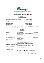
Summary of Contents for Spinal Tap Pinball

Page 1: ...S ENTS THEMELAND PROUDLY PRESENTS THEMELAND PROUDLY PRESENTS THEMELAND PROUDLY PRESENTS SENTS THEMELAND PROUDLY PRESENTS THEMELAND PROUDLY PRESENTS THEMELAND PROUDLY PRESENTS SENTS THEMELAND PROUDLY PRESENTS THEMELAND PROUDLY PRESENTS THEMELAND PROUDLY PRESENTS SENTS THEMELAND PROUDLY PRESENTS THEMELAND PROUDLY PRESENTS THEMELAND PROUDLY PRESENTS ENTS THEMELAND PROUDLY PRESENTS THEMELAND PROUDLY P...

Page 2: ... Bumper Mini Wiring Harness 19 Spot Targets stand up targets 20 Flipper Mechanisms 22 Auto Ball Launch Mechanism 24 Ball Plunger parts 25 Pop Bumpers 28 Slings 30 Vertical Up Kicker VUK 31 Ball Trough 32 Mains Switch Box Voltage Adjustment Diagram 33 Power Rectifier Regulator PCB 35 Audio PCB 37 Solenoid Driver PCBs H 0012 39 Flipper Actuator Opto Mechanisms 40 Flipper Control Description 41 Flipp...

Page 3: ...in case there are updates or service notes that may have been implemented after printing We guarantee all circuit boards manufactured by us for life We are unable to extend this to PCBs manufactured by outside vendors so those specific boards have a 12 months warranty from the date of original purchase All other parts of your machine are covered for 12 months Some trim or decoration parts can be ea...

Page 4: ...n 2013 by myself a er several years making replacement pinball machine PCBs in my small home electronic workshop My wife of 40 years Karen I decided that we would start a factory in China and manufacture pinball machines Three years into the project Karen passed away and that created many serious financial and personal hurdles that had to be overcome In 2020 Homepin moved from China to Taiwan and b...

Page 5: ...nd adjustments of the machine covered in the service manual to maximise your playing experience Best wishes for the future Mike Kalinowski Managing Director Homepin Taiwan Company Limited support homepin com Homepin offers our sincere thanks to the following companies and people for their assistance or guiding ideas no ma er how small or large and in no par cular order Many Homepin customers Our lo...

Page 6: ... The other end plugs into a USB port of your PC Start the updating program by double clicking on the HOMEPIN_UPDATE_TOOL bat file in the downloaded unzipped folder power to the pinball machine should be on Once the panel opens select the correct port for the USB updating cable and then also select the new version of the software you wish to install Press Update Game and another panel will open show...

Page 7: ...ature 30 C 80 C Inhibit Operation Voltage 0 5V Programming 1 Ensure all switches are in the normal position 2 Press AND HOLD the programming switch above the LED for 3 seconds the LED will blink slowly RELEASE the switch then press AND HOLD the switch a second time for a further 3 seconds and the LED will blink quickly The unit is now ready to program with your desired coin or token 3 Keeping the ...

Page 8: ... shows RED Press the G button until the LED strip shows GREEN Press the B button until the LED strip shows BLUE Press the power on o ffbutton to exit programming mode to point the remote at the receiver for it to operate Press hold G for 5 seconds LED strip will flash GREEN 3 times when paired to pair TX to RX Press hold W for 5 seconds LED strip will flash WHITE 3 times when no longer paired to un p...

Page 9: ...e START button to accept a choice or change a setting from on to off for example When finished adjusting things in the menu use the MENU button on the door board to save your changes and exit the menu The video game is set ON by default and this can be turned OFF in the Game Settings section of the menu Adult mode is disabled OFF by default and must be turned ON to enable Adult mode Use caution and...

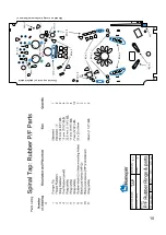
Page 10: ...10 Mounted on post top of playfield plastic Mounted on moving mechanism up down post ...

Page 11: ...ts Green thin GI 10 J14 P4 RIGHT Sling Blue thin GI 11 J14 P5 LEFT Sling Black White thin GI 12 J14 P6 Flash red 1W Green White thin GI 13 J14 P7 Down wht 1W Red White thin GI 14 J14 P8 Pop Bumper LEFT Up red LEDs Blue White thin GI 15 J14 P9 Flash red 1W Green White thin GI 13 J14 P7 Down wht 1W Red White thin GI 14 J14 P8 Pop Bumper LOWER Up red LEDs Blue White thin GI 15 J14 P9 Flash red 1W Gre...

Page 12: ...in 50V LEFT Pop Bumper 14 4 White thin 50V RIGHT Pop Bumper KEY KEY KEY KEY KEY 15 2 Grey thin 50V MIDDLE Pop Bumper 16 1 Purple THICK 50V V U K BIG BOTTOM 10 J9 FUSE 3 RIGHT DRIVER BOARD 50V SUPPLY YELLOW WIRE 17 9 Black thin SWITCH RAMP UP ALLOWS ACCESS TO STAGE 18 8 Brown thin SWITCH RAMP DOWN BLOCKS ACCESS TO STAGE 19 7 Yellow White thin 50V RIGHT SLING 20 6 Purple thin 50V LEFT SLING 21 5 Gre...

Page 13: ...CB yellow P7 Launch Warn signal IN from H 0106 5 opto board VIA flipper board pink J16 Cabinet P1 Left Flipper IN from flipper opto board cabinet push button blue P2 Right Flipper IN from flipper opto board cabinet push button yellow P3 5V N C P4 Tilt IN from plumb bob green P5 Menu switch on door PCB orange white P6 Enter switch on door PCB grey J15 Cabinet P1 Coin ONE IN optically isolated usually ...

Page 14: ...T SPINNER POD LIFT UP POS ROW 1 WHITE BLUE BLACK BLUE YELLOW GREEN ORANGE WHITE PURPLE WHITE GREEN WHITE RED WHITE YELLOW WHITE BLACK WHITE ORANGE WHITE ROW 2 ROW 3 ROW 4 ROW 5 ROW 6 ROW 7 ROW 8 COL 8 COL 7 COL 6 COL 5 COL 4 COL 3 COL 2 COL 1 R O W S C O L U M N S 63 55 47 39 31 23 15 7 62 54 46 38 30 22 14 6 61 53 45 37 29 21 13 5 60 52 44 36 28 20 12 4 59 51 43 35 27 19 11 3 58 50 42 34 26 18 10...

Page 15: ... H 0124 18 UNUSED 10 RESERVED 2 RESERVED R4 Orange White J4 Pin 5 59 VOLUME FOUR H 0118 51 GIG CANCELLED H 0120 VIA H 0118 43 S HENGE ARROW VIA H 0123 35 RIGHT SPINNER ARROW H 0124 27 T ROLLOVER H 0125 19 UNUSED 11 RESERVED 3 RESERVED R5 GREEN J4 Pin 4 60 VOLUME FIVE H 0118 52 LEFT OUTLANE H 0096 VIA H 0118 44 SKILL SHOT BOTTOM VIA H 0123 36 D T SMALL BREAD H 0123 28 A ROLLOVER H 0125 20 UNUSED 12...

Page 16: ...850 3000 2 x coils 850T x 0 56mm 3000T x 0 20mm General HP 40 1200 9 x coils 1200T x 0 40mm Drop Targets Reset HP 1000 large frame 1000T x 0 57 Kick Out Hole HP 28 800 Up Post HP ES 110 Dual windings 12VDC 2A 450T x 0 61mm 2000T x 0 15mm Solenoid Pod Doors Open HP 0837B 12VDC 1A 10mm stroke Solenoid Pod Push Ball HP 0530B 6VDC 300ma 10mm stroke Solenoid Bell JF 0530B 12VDC 300ma 10mm stroke ball t...

Page 17: ...E VOL DN KEY P1 TOP BLUE TO J16 P1 RED FROM R FLIP 5V RED 5V BLACK GND L FLIP 4 PIN P1 TOP TO CAB BUSS PCB PLUMB BOB TILT GREEN TO J16 P4 BLACK GND TO CAB BUSS PCB YELLOW TO J16 P2 RED TO L FLIP 5V BLACK GND R FLIP 4 PIN P1 TOP TO CAB BUSS PCB RED WHITE START LED RED 12V BLACK WHITE START SW START BUTTON BLACK GND TO CAB 12V BUSS SMALL SPADE CONN LARGE SPADE CONN CABINET WIRING CONNECTIONS HEADBOX...

Page 18: ...E SIDE VIEW RIGHT LEFT MIDDLE BLUE WHITE YELLOW WHITE BLACK WHITE RED WHITE GREEN WHITE WIRE SIDE VIEW TOP OF PLAYFIELD HOMEPIN H 0057 INTERCONECT HOMEPIN H 0057 INTERCONECT SOL 50V P10 WIRING CONNECTIONS TO HARNESS MIDDLE POP COIL P2 FROM MIDDLE SOL DRIVER PCB LEFT POP COIL P5 RIGHT POP COIL P4 LED 12V LED BODY DOWN LED UP LED FLASH MIDDLE SW LEFT SW SW WIRE COMMON RIGHT SW W H IT E G RE Y TO SW ...

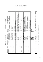
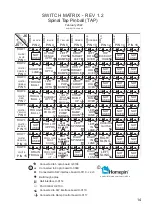
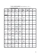
Page 19: ...19 TAP 22 June 2022 ...

Page 20: ...20 TAP 22 June 2022 ...

Page 21: ...21 TAP 22 June 2022 ...

Page 22: ...22 TAP 22 June 2022 ...

Page 23: ...23 TAP 22 June 2022 Parts Listing for Ball Auto launch Mechanism ...

Page 24: ...24 TAP 22 June 2022 MK ...

Page 25: ...25 TAP 22 June 2022 MK ...

Page 26: ...26 TAP 22 June 2022 Parts Listing for Homepin Pop Bumper MK ...

Page 27: ...27 TAP 22 June 2022 MK ...

Page 28: ...28 MK 22 June 2022 TAP ...

Page 29: ...29 MK 22 June 2022 TAP ...

Page 30: ...30 TAP V U K 1 1 2 2 3 3 4 4 5 5 6 6 7 7 8 8 A A B B C C D D E E F F ...

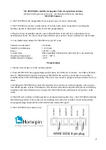
Page 31: ...31 1 1 2 2 3 3 4 4 5 5 6 6 7 7 8 8 A A B B C C D D E E F F TAP Ball Trough ...

Page 32: ...32 ...

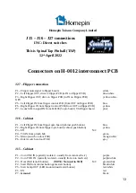
Page 33: ...33 Power Rectifier Parts Placement H 0112 ...

Page 34: ...34 ...

Page 35: ...35 TAP Audio PCB Parts Placement Audio PCB Parts Placement ...

Page 36: ...36 ...

Page 37: ...37 ...

Page 38: ...38 ...

Page 39: ...39 ...

Page 40: ...mute signal ground and the 12 50 volt supplies are daisy chained from the right flipper board across to the left The 50V is fused on each flipper control board while the 12V is fused at the Interface board H 0012 by F4 There is a shorting link on this board that will over ride the mute signal and allow the test switch on this board to operate the flipper for adjustment and testing The connections to ...

Page 41: ...41 ...

Page 42: ...42 TAP ...

Page 43: ...43 ...

Page 44: ...44 ...

Page 45: ...45 ...

Page 46: ...46 5 x Opto H 0106 Shooter Lane Stonehenge Ramp VUK Left Railway Subway Close link to disable ball launch timer ...

Page 47: ...47 ...

Page 48: ...48 H 0116 Exploding Drummer Control ...

Page 49: ...49 H 0117 Ramp Control ...

Page 50: ...50 Opto Rollover Switches ...

Page 51: ...51 Opto Rollovers ...

Page 52: ...ter test mode use the up down buttons to allow easy adjustment of elevator optos etc POD Control 3 x PCBs are linked with an IDC cable Board link cable must be connected to all 3 boards for correct operation ...

Page 53: ...53 POD Control ...

Page 54: ...54 Hall Effect Spinners ...

Page 55: ...MADE IN TAIWAN TAIWAN CO LTD BY THIS IS PINBALL ...

Reviews: