background image

Honda Dealer: Please give a copy of these instructions to your customer.

INSTALLATION

INSTRUCTIONS

Accessory

Application

© 2015 American Honda Motor Co., Inc. - All Rights Reserved.

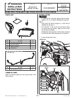
PARTS LIST

87972-HL4-A001

1 of 7

Publication No.

MII 15262

Issue Date

September 2015

(1)

(4)

(2)

(3)

LED HEADLIGHT 

P/N 08V71-HL4-A00

SXS1000M3/M3P/M5P

No.

Description

Qty

(1)

Installation Instructions URL

1

(2)

Right LED headlight

1

(3)

Left LED headlight

1

(4)

Headlight cap

4

(1)

No.

Description

Qty

(1)

LED Headlight sub harness

1

LED HEADLIGHT SUB HARNESS
Sold separately

TORQUE CHART

Refer to the Service Manual for the torque values of the 
removed parts.

INSTALLATION

   CAUTION

•  To prevent burns, allow the engine, exhaust system, 

radiator, etc., to cool before installing the accessory.

NOTE:

•  Disconnect the battery negative (-) cable before 

installing this accessory.

•  The  memory  of  the  clock  will  be  erased  when 

you disconnect the battery. Reset the clock after 
reconnecting the battery.

•  Reinstall the removed parts on the vehicle and make 

sure that the wires and harnesses are not pinched.

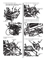
SCREW

Loosen.

BAND

DUCT

1.  Loosen the band as shown.

<Right side>

Summary of Contents for 08V71-HL4-A00

Page 1: ...tion Qty 1 LED Headlight sub harness 1 LED HEADLIGHT SUB HARNESS Sold separately TORQUE CHART Refer to the Service Manual for the torque values of the removed parts INSTALLATION CAUTION To prevent bur...

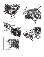
Page 2: ...NT DOOR Remove the bolts as shown FRONT BUMPER 3 Remove the front bumper as shown 5 Remove the left front door as shown 4 Remove the clips as shown Left side BOLT Repeat on the right side BOLT BOLT 2...

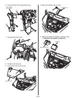
Page 3: ...rd as shown 7 Remove the bolt as shown 8 Repeat on the right side FRONT HOOD 9 Remove the front hood as shown BOLT 10 Remove the battery stay as shown 11 Remove the battery and battery cushion as show...

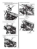
Page 4: ...tering the duct 13 Remove the relay and fuse box as shown 14 Remove the fuse holder and starter relay switch as shown RELAY FUSE BOX FUSE HOLDER STARTER RELAY SWITCH CLIP BATTERY CABLE CLIP CLIP 15 Re...

Page 5: ...from entering the duct FRONT FENDER DUCT FRONT FENDER Under side 19 Remove the clip and connector as shown 20 Repeat Steps 18 and 19 on the right side 21 Remove the headlight harness as shown SCREW L...

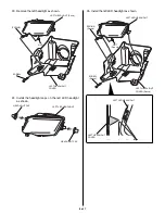
Page 6: ...eadlight as shown LEFT HEADLIGHT COVER LEFT HEADLIGHT Save LEFT LED HEADLIGHT HEADLIGHT CAP HEADLIGHT CAP SCREW SPRING NUT 25 Install the left LED headlight as shown LEFT HEADLIGHT COVER Reuse LEFT HE...

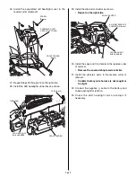
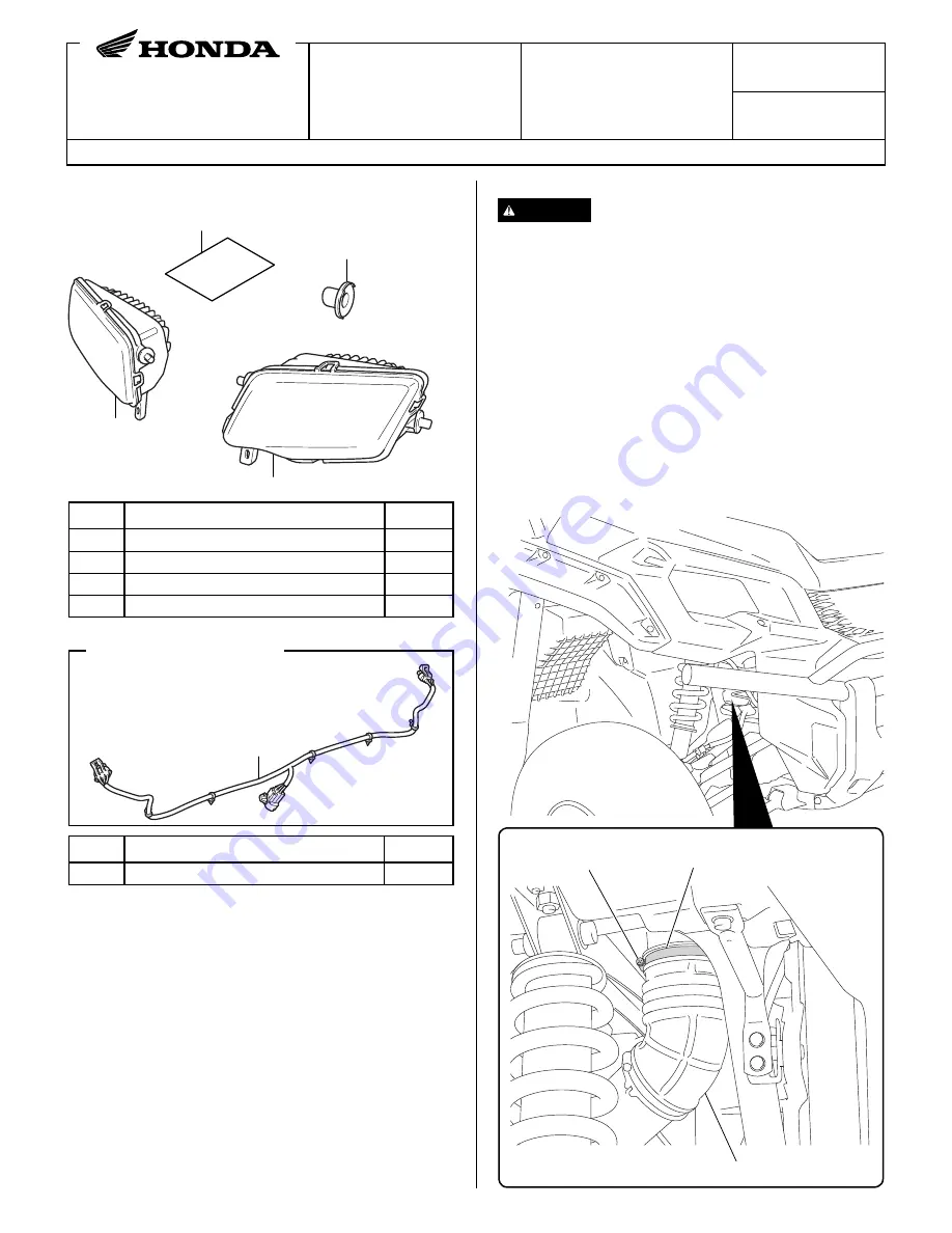
Page 7: ...ONT FENDER CLIP 3 PIN WATERPROOF CONNECTOR Black 30 Install the caps and front fender in the reverse order of removal Remove the covered shop towel or similar 29 Install the clip and connector as show...

Reviews: