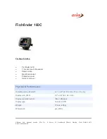
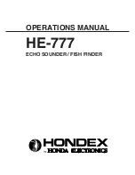
background image

OPERATIONS MANUAL

HE-777

ECHO SOUNDER / FISH FINDER

Summary of Contents for HE-777

Page 1: ...OPERATIONS MANUAL HE 777 ECHO SOUNDER FISH FINDER...

Page 2: ...on this manual partially due to change of specifications and so on If you have questions on this manual may we trouble you to inform us We thank you very much for purchasing HE 777 Please be sure to r...

Page 3: ...ION WITH DISPLAY UNIT 11 INSTALLATION OF THE UNIT 13 HOW TO SEE THE DISPLAY AND DESCRIPTIONS OF CONTROL KEYS 15 POWER ON OFF OF THE DISPLAY UNIT 16 POWER ON OFF 16 TO USE FOR THE FIRST TIME AFTER PURC...

Page 4: ...28 COLOR 28 EXP RATE 28 B L EXP 28 B L POSI 28 DIGIT 28 DIG POSI 28 SCALE UNIT 29 TEMP UNIT 29 TEMP ADJ 29 C ECHO 29 STC 29 PW REDUCER 29 SPLIT SCR 29 DISPLAY 30 RESET 30 OPTIONS 31 TROUBLE SHOOTING 3...

Page 5: ...install it simply It causes to the accident like human damage Please be sure to install correctly according to descriptions on Installation of the unit of this manual Do not use the information displ...

Page 6: ...boat If feet of crews or operating equipments are caught in cables it causes to the acci dent Do not put the heavy objects on cables or do not bend cables excessively Do not disassemble or modify the...

Page 7: ...e should be done while you ventilate well inside the boat Volatile gas from solvent or etc causes to toxic symptoms When you work using electric tools please keep your hands dry If your hands are wet...

Page 8: ...ses to faulty Please be more careful to operate or store it under direct sun ray in the summer time and use it carefully where it is in the shade as possible Avoid the place where it is high temperatu...

Page 9: ...utline of bottom or nature of bottom on the screen in different colors Displayed image Each time when image is sent by one line to the left ultrasonic wave is transmitted and it s reflected echo is di...

Page 10: ...mitted wave is reflected strongly you can distinguish the density of fish school according to the strength of reflected echo that is different color Normally we tend to think the larger fish school on...

Page 11: ...bottom image becomes thick and the second reflection becomes easily to appear On the other hand at the soft bottom like sand or mud the reflection becomes weak and bottom image becomes thin and the se...

Page 12: ...ES Please check if all of the below described items are packed when you use the unit for the first time Display Unit with bracket 1 Operations manual 1 Power Supply cable 1 Fuse 10A 1 Disk Plate 6 Scr...

Page 13: ...9 DEMENSIONAL DRAWING DISPLAY Drawing of holes for installing bracket Confirm no obstacles in this area 11 11 11 11 100 170 276 308 100 8 6 6 9 278 254 340 335 200 120 mm A A A A A A...

Page 14: ...cur DANGER Perfect water proof treatment should be done when you install the water tempera ture sensor through the hull Unless perfect it causes to marine disaster due to inundation When you work usin...

Page 15: ...11 CONNECTION WITH DISPLAY UNIT NMEA GGA VTG Output Transducer Fuse Holder 10A Battery 11 35V DC W B Temp Sensor Option 5P 8P 6P 2P...

Page 16: ...y Low F High F 3 2 1 5 4 1 2 3 4 5 1 2 3 4 5 6 7 1 2 3 4 5 6 1 GND 2 RXD C 3 RXD H 4 N C 5 TXD 6 DC12V out max 200mA 1 2 3 4 5 6 DATA OUT RS232CLEVEL For EXTERNAL POWER 12V DC 200mA max 5V 1k 470 1 2...

Page 17: ...re to seal unused 6 holes by stickers to prevent damages from splash etc Pan head screw with spring washer M6X10 Hexagon bolt M8X20 Procedure of installation 1 Selection of installation method Unit is...

Page 18: ...ied with the unit You must use hexagon bolts bigger than M8X35 and install firmly Screw M6X20 Bolt M8X35 M8 HEX Nut 8mm Washer 8mm S Washer 3 Putting the disk plate Put the supplied disk plates on six...

Page 19: ...hown when Auto Gain is set HOW TO SEE THE DISPLAYAND DESCRIPTIONS OF CONTROL KEYS 0 10 20 30 m AR N 34 43 356 E 137 37 456 341 17 8N 50 G3 0 200 G3 0 18 0 17 5 4 Power Brightness Color Bar 1 Latitude...

Page 20: ...RTANT NOTICE The HE 777 is designed to use Hondex transducer If you use other brand transducer please ask your local dealer to make sure it works properly 1 By rotating POWER BRIGHT switch clockwise a...

Page 21: ...Set language 4 Return to sounder mode by menu key NOTE Once you set the language no need to set again from next time use ECHO SIMULATION For demonstration purpose echo simulation is available With pr...

Page 22: ...tom is displayed in weaker color and the first reflection of the bottom is shown in red Second Reflection The first received echo reflected from bottom is called the first reflection first echo Genera...

Page 23: ...increase the sensitivity Each time when you press GAIN key sensitivity increases and number indicating sensitivity increases To set GAIN level in dual frequency mode press menu key shortly for select...

Page 24: ...size of number is selectable by menu 2 2 Unit of the depth is selectable among Meters Feet Fathoms and Brazas by Menu 3 IMPORTANT The maximum detectable depth varies depending upon the water or botto...

Page 25: ...een AUTO RANGE mode is NOT recommendable when the transducer was installed inside of the hull To decrease the depth display range Each time when you press RANGE key the depth decreases getting shallow...

Page 26: ...PANSION are selectable by Menu 2 2 In B L mode the bottom line positions are selectable BOTTOM or CENTER of screen by Menu 2 3 HISTORICAL display shows about 10 times of the sweep speed IMPORTANT In c...

Page 27: ...FT mode is NOT recommendable when the transducer was installed inside of the hull SHIFT SHIFT To shift to shallow depth Each time when you press SHIFT key the display range be comes shallow To shift t...

Page 28: ...NIT M FT FA BR TEMP UNIT TEMP ADJ C ECHO OFF 1 2 STC OFF L M H PW REDUCER A B C SPLIT SCR L R U L DISPLAY P PR L LR RESET TO FINISH MENU MENU 3 FACTORY SET LANGUAGE MENU SETTING TO FINISH MENU OTHER S...

Page 29: ...is selected moving cursor in yellow square with Select Select Set or Set key Selected item is covered with frame Installation Portrait Installation Landscape Select key Select key Set key Set key Sele...

Page 30: ...IN OFF Manual control L Low Gain Setting M Medium Gain Setting H High gain Setting AUTO R S OFF Manual control RNG Depth Range is automatically changed by bottom depth SFT Picture is automatically shi...

Page 31: ...ow and deep limits by RANGE key with watching RED BAR on the right edge of sounder image For ANCHOR alarm setting Set shallow and deep limits by RANGE key with watching RED BARs on the right edge of s...

Page 32: ...own by red bar on the right side of picture B L EXP Bottom Lock Bottom is displayed as straight line in any contour ex pansion rate is selectable among 2 times X2 4 times X4 or 8 times X8 for each dep...

Page 33: ...tes small noise or interfer ence from other sounder selectable OFF or ON STC Sensitivity Time Control circuit eliminates clutters or noises near the surface selectable Low Medium High settings High se...

Page 34: ...30 DISPLAY Display mode is selectable RESET Return to First setting mode P Portrait PR Portrait Reverse L Landscape LR Landscape Reverse...

Page 35: ...F05 In dash plate WP04 Water temperature extension cable EK11 M4 X 8 SUS Mushroom head screw black coating on top X 4 Bolt M8 X 40 X 4 Mushroom tapping screw M5 X 20 X 4 Metal plate Right Left X 1 eac...

Page 36: ...r bubbles wind is easily at high speed sailing It results in no display Influence of air bubble when the boat runs across the wakes of another boat Recharge the battery Tighten firmly Clean and remove...

Page 37: ...cles oyster shell rubbish or etc attach on the surface of transducer Install it inside the hull bottom or liquid is dirty Increase the sensitivity Or set Auto Gain Remove the attachment well Remove th...

Page 38: ...EXP L L BL L L HIS L IMAGE STYLE Portrait P Reverse Landscape L Reverse MENU English Italian Spanish Thai Korean Chinese SPLIT SCREEN side side or upper lower EXPANSION X2 X4 X8 B L EXP X2 X4 X8 or 5...

Reviews: