

Sensing and Control, 11 West Spring Street, Freeport, Illinois 61032
Printed in U.S.A. © Copyright 2000—Honeywell
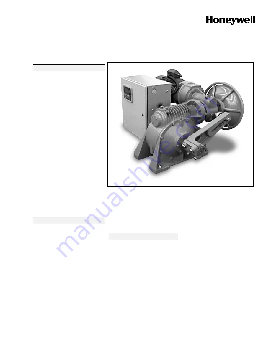
Herculine
11280S
Smart Actuator
61-86-03-13
9/01
Page 1 of 14
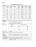
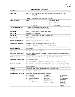
Specification
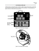
Figure 1 Herculine 11280S Smart Actuator
Overview
Honeywell’s
HercuLine
11280S Smart
actuators incorporate all of the high
quality and reliable features of the
traditional
HercuLine
actuators plus
the added benefits of a microprocessor-
based Enhanced Electronics Unit (EEU).
These additional benefits provide:
•
•
•
Faster set-up and commissioning
Network capability
Health parameter monitoring for
proactive maintenance planning.
HercuLine 11280S Smart
actuators
enable operation at maximum process
efficiency, minimal downtime, and
access to all actuator parameters for
real-time business decisions.
Honeywell’s 11280S actuators are
industrial rated and engineered for very
precise positioning of dampers and
valves. The HercuLine 11280S
performs especially well in extremely
demanding environments requiring
continuous duty, high reliability, and low
maintenance. Typical applications are
ID/FD fan dampers, furnace pressure
dampers, coal mill dampers, burner tilts
and more.
Actuator Operation
Microprocessor-based electronics
continually monitor the performance,
health, and position of the actuator for
repeatable positioning and response to
demand signal.
A double reduction worm gear set
combines with a variable speed motor
controller (inverter) that is continuous
duty rated for accurate and repeatable
positioning of final control elements.
The worm gear set combination also
functions as a brake, capable of holding
greater than two times the output torque
in a back-driving condition.
Control options are available to
interface with a modulating 4-20 mA
input signal and 4-20 mA customer
feedback or remote setpoint through
Modbus. Internal balance, customer
feedback and patented slidewire
emulation is provided by a non-
contacting position sensor.
Features
Performance
•
Accurate Positioning
–
Motor/gear train provides accurate
positioning with almost
instantaneous start/stop
characteristics.
•
Non-Contact Position Sensing
–
Non-contacting sensing lowers
maintenance costs and improves
performance.
•
Duty Cycle
– Continuous duty
rated motor.
•
Full Travel Speed
– Full stroke
travel speeds as fast as 10
seconds.
•
Torque
– High torque capability in
small package (425 – 5,500 lb-ft).
•
High Accuracy
– Typically 0.25 %
of 90
°
span.
•
High Repeatability
- Typically
0.2 % of 90
°
span.
•
Characterization
– Linear, square
root or programmable user-
configured 21-point
characterization allows tailoring of
control for specific applications.
•
Input Filter Setting
– Four
programmable combinations of
input filter settings are provided to
accommodate various customers
needs. The combinations are
none, spike, low pass, or spike +
low pass filter.
•
Deadband
– Deadband is
programmable between 0.2 % to
5 % of 90
°
span.


