background image

006-08845-0000

Rev. 8 Apr/00

GNS-X

LS

FLIGHT MANAGEMENT SYSTEM

Operator’s Manual

Global

N

Summary of Contents for GNS-XLS

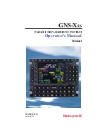
Page 1: ...006 08845 0000 Rev 8 Apr 00 GNS XLS FLIGHT MANAGEMENT SYSTEM Operator s Manual Global N ...

Page 2: ...rnational Inc Reproduction of this publication or any portion thereof by any means without the express written permission of Honeywell International Inc is prohibited For further information contact the Manager Technical Publications Honeywell One Technology Center 23500 West 105th Street Olathe Kansas 66061 Telephone 913 782 0400 ...

Page 3: ...ert Remove and Replace Title Page Remove and Replace Revision History Page Insert Ahead of Existing Revision History Page Table of Contents Remove and Replace Pages v vi xv xvi and xvii xviii Section 2 Remove and Replace Pages 2 1 2 2 2 73 through 2 76 and 2 79 2 80 Section 3 Remove and Replace Pages 3 1 through 3 4 3 15 3 16 3 36 1 3 36 2 and 3 109 3 110 Section 8 Remove and Replace Section 8 Cov...

Page 4: ...ding to the following instructions Cover Page Remove and Replace Revision History Page Insert Ahead of Existing Revision History Page Table of Contents Remove Pages XV and XVI and Replace with Pages XV through XVIII Section 8 Remove and Replace Title Page Remove and Replace Page 8 1 8 2 Remove and Replace Page 8 35 8 36 with Pages 8 35 through 8 70 Back Cover Page Remove and Replace Back Binder In...

Page 5: ...Number 006 08845 0000 This revision consists of the following Add Waypoint Type Identifier 2 54 3 40 3 45 3 48 3 49 3 62 Revise Procedure Turn 3 41 3 42 3 43 3 44 Remove H Hot Key 3 57 3 58 3 61 Add Fuel Used Reset Function ix 2 48 3 105 3 106 Typographic Administrative Corrections Inside Front Cover 2 1 2 2 3 1 3 2 3 39 3 59 3 60 Back Covers ...

Page 6: ...the following Add Company Routes vi 2 2 3 36 1 3 36 2 I 2 Add Dedicated DME Interface 2 57 Add Approach Note 3 36 3 Typographic Administrative Corrections Front Covers 2 1 2 4 2 9 2 10 2 11 2 12 2 27 2 28 2 79 3 1 3 2 3 3 3 4 3 42 3 43 7 12 7 15 7 20 7 22 7 54 7 55 7 56 7 57 7 58 7 59 Back Covers GNS XLS Flight Management System R 1 Rev 5 Sep 97 ...

Page 7: ...1 6 SPACE SP KEY 1 6 ENTER Key 1 6 DISPLAY SELECTOR KEYS 1 6 PREVIOUS PRV KEY 1 7 NEXT NXT KEY 1 7 LINE SELECT KEYS 1 7 COLORS 1 8 SECTION 2 PAGE DISPLAY DEFINITIONS 2 1 PAGE DISPLAYS AT POWER UP 2 1 SELF TEST PAGE 2 1 INITIALIZATION PAGE 2 1 FLIGHT PLAN SECTION FPL KEY 2 2 FLIGHT PLAN PAGES 2 2 FLIGHT PLAN LIST 1 1 Page 1 of 1 2 2 Table of Contents GNS XLS Flight Management System Rev 4 Sep 97 i ...

Page 8: ...F SUBSECTION 1 4 Page 1 of 4 2 21 VLF SUBSECTION 2 4 Page 2 of 4 2 21 VLF SUBSECTION 3 4 Page 3 of 4 2 23 VLF SUBSECTION 4 4 Page 4 of 4 2 24 IRS INS SUBSECTION PAGES 2 25 IRS or INS SUBSECTION 1 2 Page 1 of 2 2 25 IRS SUBSECTION 2 2 Page 2 of 2 2 25 VPU SUBSECTION PAGES 2 26 VPU SUBSECTION 1 4 Page 1 of 4 2 26 VPU SUBSECTION 2 4 Page 2 of 4 2 26 VPU SUBSECTION 3 4 Page 3 of 4 2 27 VPU SUBSECTION ...

Page 9: ...TUS 2 42 PLAN 2 8 Page 2 of 8 TRIP PLAN 2 44 PLAN 3 8 Page 3 of 8 FUEL PLAN 2 46 PLAN 4 8 Page 4 of 8 FUEL FLOW 2 47 PLAN 5 8 Page 5 of 8 DATE GMT 2 47 PLAN 6 8 Page 6 of 8 AIRCRAFT WEIGHT 2 48 PLAN 7 8 Page 7 of 8 FDE PREDICTION 2 49 FDE EXCLUDE SATS 1 1 Page 1 of 1 2 51 PLAN 8 8 Page 8 of 8 FDE COMPUTATION 2 51 HEADING SECTION HDG KEY 2 53 HEADING PAGE 2 53 HEADING VECTOR 1 1 Page 1 of 1 2 53 TU...

Page 10: ... Page 2 of 2 2 64 WAYPOINT SECTION 2 65 WAYPOINT PAGES 2 65 DATABASE WPT 1 1 Page 1 of 1 2 65 SPECIAL DATABASE WAYPOINTS 2 69 PILOT ENTERED WPT Personalized Waypoint 2 69 OFFSET WAYPOINT 2 70 SPECIAL WAYPOINTS 2 71 POWER OFF WAYPOINT 2 72 OCEANIC REPORTING WAYPOINTS 2 72 OBSOLETE WAYPOINT 2 73 MESSAGES MSG Key 2 73 SYSTEM MESSAGES 2 74 ACTION REQUIRED 2 74 ADVISORY 2 75 SENSOR MESSAGES 2 78 SECTIO...

Page 11: ...NG A WAYPOINT 3 9 Adding Oceanic Waypoints 3 10 ERASING A STORED FLIGHT PLAN 3 11 USING DUPLICATE WAYPOINT IDENTIFIERS 3 11 REVIEWING WAYPOINT DATA COORDINATES FLIGHT PLAN PAGES ONLY 3 12 FLIGHT PLAN FPL SELECTION 3 13 INITIAL LEG SELECTION 3 14 BEFORE TAXI IRS EQUIPPED 3 15 RUNWAY LINE UP IRS EQUIPPED 3 15 IRS VLF RPU GPS AND OR VPU EQUIPPED 3 15 VLF RPU AND OR VPU EQUIPPED ONLY 3 15 SIDs STARs A...

Page 12: ...GE 3 29 ERASING A STAR FROM A STORED FPL OR THE ACTIVE FPL PAGE 3 30 ADDING WAYPOINTS WITHIN A STAR 3 31 DELETING WAYPOINTS OF A STAR 3 31 ENTERING AN APPROACH ON A STORED FPL OR THE ACTIVE FPL PAGE 3 32 REVIEWING AN APPROACH FROM A STORED FPL OR THE ACTIVE FPL PAGE 3 34 EDITING AN APPROACH FROM A STORED FPL OR THE ACTIVE FPL PAGE 3 34 ERASING AN APPROACH FROM A STORED FPL OR THE ACTIVE FPL 3 35 D...

Page 13: ...RPORT 3 54 PSEUDO VORTAC SELECTED COURSE 3 55 USING HEADING VECTOR 3 57 PROGRAMMING A HEADING VECTOR 3 57 CHANGING HEADING VECTOR WHILE IN HEADING SELECT MODE 3 58 CHANGING TO WAYPOINT WHILE IN HEADING SELECT MODE 3 58 CANCELING HEADING SELECT MODE 3 59 PROGRAMMING AN INTERCEPT 3 59 PROGRAMMING A HEADING INTERCEPT TO THE FINAL APPROACH COURSE 3 61 PROGRAMMING A HOLDING PATTERN 3 63 REVIEWING EDITI...

Page 14: ... ENROUTE 3 76 PROGRAMMING VERTICAL PATH DESCENTS 3 76 Using Database DB FPA 3 77 Using Default DEF FPA 3 77 Using Manual MAN FPA 3 77 Using Automatic AUTO FPA 3 78 EDITING ALTITUDE CONSTRAINTS 3 79 Option 1 Using VNAV Page 3 79 Option 2 Using VNAV FPL WAYPOINT Page 3 79 Option 3 Using the VNAV WAYPOINT Page 3 80 DIRECT TO VNAV WAYPOINT AS LATERAL WAYPOINT 3 81 DIRECT TO VNAV WAYPOINT 3 83 CREATING...

Page 15: ... Groundspeed 3 102 To Return To Automatic Groundspeed 3 102 To Enter A Manual Fuel Flow 3 102 To Return to Automatic Fuel Flow 3 102 VERIFYING OR CHANGING DATE AND TIME 3 104 VERIFYING OR CHANGING AIRCRAFT WEIGHT PARAMETERS 3 105 RESETTING FUEL USED 3 106 SPECIAL PROCEDURES 3 107 PILOT ENTERED LEG CHANGE 3 107 PREVENTING AUTOMATIC LEG CHANGES 3 109 DEAD RECKONING DR TO PRIMARY NAVIGATION MODE VLF ...

Page 16: ...ANCE 3 122 PRESENT POSITION AS A WAYPOINT 3 123 NAVIGATION AT EXTREME LATITUDES 3 124 TRUE HEADING 3 124 Aircraft Equipped With TRUE MAG Switch 3 124 Aircraft Not Equipped With A TRUE MAG Switch 3 125 SET HEADING ENTRY 3 125 LOSS OF POWER IN FLIGHT 3 126 CREATING CHANGING PILOT ENTERED PERSONALIZED WAYPOINTS 3 127 Creating Pilot Entered Personalized Waypoints 3 128 Changing Pilot Entered Personali...

Page 17: ...nagement Unit DMU 7 2 Antenna Switching Unit ASU 7 2 Satellite Communications Unit SCU 7 3 High Power Amplifier Low Noise Amplifier HPA LNA 7 3 Satellite Antenna 7 3 PAGE DISPLAY DEFINITIONS 7 3 AFIS Flight Plan List Page 7 3 Flight Plan Progress NAVIGATION Page 5 7 4 AFIS Menu Page 7 6 AFIS FLT PLAN Pages 7 7 AFIS FLT PLAN Page 1 7 7 Fuel and Time Require ments 7 7 AFIS FLT PLAN Page 2 7 9 Weight...

Page 18: ...MSG Page 7 18 OPERATING MODES Page For AFIS Users Equipped with Satellite Data Communications System 7 18 AUTO REPORT 7 18 AUTO WX UPDT weather update 7 19 VHF LINK CONTROL Page 7 20 SAT LINK CONTROL Page 7 20 OPERATING MODES Page For AFIS Users NOT Equipped with Satellite Data Communications System 7 21 AUTO REPORT 7 21 AUTO WX UPDT weather update 7 22 Active Flight Plan Page for AFIS Flight Plan...

Page 19: ...2 Terminal Weather Menu Data update and Review 7 33 To insert a new identifier 7 34 To delete text when there is no data entry in progress 7 34 Winds Aloft Menu Data update and Review 7 34 To insert a new identifier 7 35 To delete text when there is no data entry in progress 7 36 Recalling AFIS Flight Plan 7 36 Recall Option 1 7 36 Recall Option 2 7 37 Sending a Text Message or pdc 7 38 To Return ...

Page 20: ...urning VHF Network OFF 7 48 Turning VHF Network ON 7 49 Turning AUTO to MAN or OFF 7 50 Returning to AUTO 7 50 Turning Satellite Network OFF 7 51 Turning Satellite Network ON 7 52 Turning AUTO to MAN 7 53 Returning to AUTO 7 53 SELECTING OPERATING MODES For AFIS Users NOT Equipped with Satellite Data Communications System 7 54 Auto Reporting 7 54 Turning AUTO REPORT OFF 7 54 Returning to AUTO REPO...

Page 21: ...7 65 To insert a new identifier 7 65 SECTION 8 AFIS DMU P N 400 045500 0003 WITH MOD 13 OR LATER DESCRIPTION 8 1 Initialization Page 8 1 AFIS Menu Page 8 2 Weight and Balance Page J32 Configuration 8 3 Weight and Balance Page J41 Configuration 8 4 Station Menu Page J32 Configuration 8 6 Station Menu Page J41 Configuration 8 7 Weather Menu Page 8 8 Dispatch Menu Page 8 8 Airport Analysis Page 8 9 D...

Page 22: ...r Update 8 26 Sending and Receiving AFIS Messages 8 27 Station Review Update 8 27 J32 Configuration 8 27 J41 Configuration 8 30 End of Flight 8 32 Close Out of Flight 8 32 AFIS DMU P N 400 045500 0130 With MOD 1 DESCRIPTION 8 35 Initialization Page 8 35 AFIS Menu Page 8 36 Weight and Balance Page J32 Configuration 8 37 Weight and Balance Page J41 Configuration 8 38 Station Menu Page J32 Configurat...

Page 23: ...ion 8 49 J41 Configuration 8 51 Dispatch Review Update 8 53 Airport Analysis Review Update 8 55 Hold Review Update 8 56 Enroute 8 58 Weather Update 8 58 Divert Review Update 8 59 Initialization Review or Update 8 60 Sending and Receiving AFIS Messages 8 61 Station Review Update 8 61 J32 Configuration 8 61 J41 and EMB120 Configuration 8 63 End of Flight 8 66 Close Out of Flight 8 66 AFIS COMMUNICAT...

Page 24: ...Table of Contents GNS XLS Flight Management System xviii Rev 7 Feb 99 THIS PAGE INTENTIONALLY LEFT BLANK ...

Page 25: ...raft This allows hardware to be eas ily moved between aircraft types without changing system configura tion The following is a summary of the digital and analog interfaces DIGITAL ANALOG AFIS Altitude Air Data Computer Altitude Rate EFIS Cross Track Deviation Fuel Flow Discretes Inertial Navigation Sensor Dual VOR DME Inertial Reference Sensor Fuel Flow VOR DME ADF XPDR COMM Heading Radio Tuning H...

Page 26: ...56 different stored flight plans each containing up to 50 waypoints Due to the way the GNS XLS database is structured waypoints must have unique identifiers However some duplicate ICAO identifiers exist for more than one waypoint In these cases the waypoint identi fiers are renamed in the database Two naming conventions are used one for four character identifiers and one for five character identif...

Page 27: ...n is arranged in sections and subsections much like chapters in a book Individual screen displays are referred to as pages Each section is selected by depressing the appropriate Display Selector Key located at the top of the GNS XLS Each subsequent push of the key will select the next page of that section A subsec tion page is selected by depressing the Line Select Key next to the topic desired th...

Page 28: ... of the Line Select Keys NOTE The illumination of the front panel and keyboard is nor mally controlled through the air craft panel lighting control MESSAGE KEY ANNUNCIA TOR MSG The MSG annunciator will flash to alert the operator that a mes sage needs to be viewed on one of the SYSTEM MES SAGES or SENSOR MES SAGES Pages Description 1 4 GNS XLS Flight Management System Rev 3 Sep 96 NAV MSG P R V N ...

Page 29: ...ppropriate to program a Holding Pattern at that way point depressing the HOLD Key accesses the Holding Pattern page If the cursor is not displayed depressing the HOLD Key accesses the POSITION FIX Page and is used for position updates and verification as well as entering the primary naviga tion mode Description 1 5 GNS XLS Flight Management System Rev 3 Sep 96 NAV MSG P R V N X T VNAV AFIS FPL ON ...

Page 30: ...rticular section The first page of a section is dis played first when a Display Selector Key is pressed With each subsequent press of the Key the next sequential page will be displayed Description 1 6 GNS XLS Flight Management System Rev 3 Sep 96 NAV MSG P R V N X T VNAV AFIS FPL ON BRT PLAN HDG TUNE HOLD BACK ENTER SP 1 2 3 4 5 6 7 8 9 0 A B D C D E F G H I J K L S T U V M N O P W X Y Z Q R NAV M...

Page 31: ...se keys are used to place the cursor in the field next to that key Each line select key controls 2 lines of text White symbols or displayed on either side of the display indi cate active Line Select Keys for each individual page Description 1 7 GNS XLS Flight Management System Rev 3 Sep 96 NAV MSG P R V N X T VNAV AFIS FPL ON BRT PLAN HDG TUNE HOLD BACK ENTER SP 1 2 3 4 5 6 7 8 9 0 A B D C D E F G...

Page 32: ...ta entered but not yet accepted by the computer Cyan Date and Times Tuned Frequencies or Codes Altitudes Green Navigation and Fuel Data General Page Data White Page Titles and Prompts Red Warnings Blue Waypoint Numbers COLORS The CDU displays are color coded to assist the operator in recogniz ing information The following is a list of these colors and their mean ings ...

Page 33: ...s extensive internal tests that must be successfully completed before proceeding further If the system detects a problem the SELF TEST display may be replaced by a NO DATA RECEIVED message The unit may have to be removed for service INITIALIZATION PAGE After the Self Test is success fully completed the INITIAL IZATION Page will be dis played Refer to Figure 2 2 DATE The current Greenwich Date is d...

Page 34: ...N FPL KEY Upon pressing the FPL Key the FLIGHT PLAN LIST 1 1 Page will be displayed and the following can be observed NOTE The FLIGHT PLAN LIST page may automatically be dis played if the ENTER key is depressed at least three times while on the initialization page FLIGHT PLAN PAGES NOTE If AFIS equipped the first page displayed after system initial ization will be the AFIS FPL LIST page in lieu of...

Page 35: ...ed through the FLIGHT PLAN LIST Page by pressing the Line Select Key corresponding to the desired flight plan number thus placing the cursor over that number then pressing ENTER Figure 2 3 Waypoint Identifiers Waypoint identifiers may consist of from one to six alphanumeric characters Up to 50 waypoint identifiers may be placed on each stored Flight Plan An identifier may be used more than once on...

Page 36: ... Arc end waypoint Automatically loaded from the data base when a non precision approach is selected FAF Final Approach Fix Automatically loaded from the data base when a non precision approach is selected MAP Missed Approach Point Automatically loaded from the data base when a non precision approach is selected fence indicating a discontinuity in the flight plan No Auto Leg changes will take place...

Page 37: ... plan Figure 2 5 DEPARTURE Page Accessed by pressing the Line Select Key adjacent to DEPART on the FLIGHT PLAN Page With the cursor over DEPART press ENTER NOTE Each field will prefill if there is only one choice for that partic ular field or DEPARTURE airport field will flash if no Departure is available A NO SIDS AVAILABLE message will appear at the bot tom of the screen DEPARTURE Departure airp...

Page 38: ...ith the cursor over ARRIVE press ENTER NOTE Each field will prefill if there is only one choice for that particu lar field or ARRIVAL field will flash if no Arrival is available and a NO STARS AVAILABLE message will appear at the bottom of the screen ARRIVAL Arrival airport identifier This field prefills if the last waypoint on the flight plan is an airport or run way or can be manually entered Fi...

Page 39: ...2 9 APPROACH Page Accessed by pressing the Line Select Key adjacent to APPROACH on the FLIGHT PLAN Page With the cursor over APPROACH press ENTER NOTE Each field will prefill if there is only one choice for that partic ular field or Approach Airport field will flash if no Approach is avail able and a NO APPROACH AVAILABLE message will appear at the bottom of the screen APCH Approach airport identi...

Page 40: ...or selected from a list made available by pressing the Line Select Key adjacent to the TRANSI TION field Figure 2 10 WAYPOINTS OF APPROACH The waypoints that constitute the APPROACH Figure 2 11 HP Holding Pattern Indicates a holding pattern is programmed at a particular waypoint Figure 2 11 PT Procedure Turn Indicates a Procedure Turn is programmed at a particular waypoint ARC DME ARC Indicates a ...

Page 41: ...SELECT Used to select the defined APPROACH Figure 2 11 ERASE Used to erase an APPROACH Figure 2 11 AIRWAY Page Enroute Airways may be manually entered on a Flight Plan Page by preceding the route or airway ident with a pound sign e g J Jet Airway V VOR Airway UG Upper Green or R Red Airway The preceding waypoint on the Flight Plan must be part of the Airway being entered in order for the Airway to...

Page 42: ...ly selected Active Flight Plan when the TO waypoint is not on the original Flight Plan Also separates non con tinuous Flight Plan segments Figure 2 13 No Auto Leg change will occur to waypoints that appear after the fence This type of fence will not cause waypoints of the active flight plan to be deleted prior to the fence if a waypoint beyond the fence is selected using the d func tion NOTE When ...

Page 43: ... option No ETE ETA ALT or DIS infor mation is displayed for waypoints beyond the missed approach fence or the flight plan discontinuity ETE Estimated Time Enroute between waypoints on the Active Flight Plan based on current groundspeed DIS Distance between each way point on the Active Flight Plan ALT Constraint altitude and way point offset of programmed VNAV waypoints for applica ble waypoints on...

Page 44: ...or to the end of the runway and the approach is straight in the altitude displayed at the MAP is computed based on a line drawn from the FAF through the MAP to a point 50 feet above the runway threshold The altitude may not be the MDA Figure 2 16 If no approach is programmed the altitude value will be the air port elevation regardless of runway selection The MAP altitude is shown in yellow The Way...

Page 45: ...t is displayed on the right The TO field may also display AR HP or PT if the waypoint indicates a DME ARC Holding Pattern or Procedure Turn The ETA field can be changed to display constraint altitude and waypoint offset distance if an altitude constraint has been programmed at the current TO way point by placing the cursor over this field and dressing the BACK Key Figure 2 17 See Section 3 for the...

Page 46: ...ght Plan is displayed in parentheses Figure 2 18 NOTE The DTK field will be dashes if the FROM waypoint or pre sent position are north of N 70 or south of S 60 Latitude unless a manual MAG VAR is entered or a discrete MAG True switch is moved to the True position GS The current groundspeed Figure 2 19 WIND The current wind direction referenced to True North and speed in knots Figure 2 19 XFILL If ...

Page 47: ...n direction around the holding pattern as entered on the HOLD Page Figure 2 20 MANUAL or AUTO Indicates the programmed exit mode as entered on the Hold Page Selecting MANUAL initiates a continuous hold at the fix until some action is taken by the pilot to exit the hold Selecting AUTO will cause the aircraft to EXIT HOLD the next time the aircraft passes over the fix Figure 2 21 If AUTO is programm...

Page 48: ... holding pattern This message appears 30 seconds prior to entering the holding pro cedure and changes to HOLDING after crossing the fix Figure 2 20 TEARDROP ENTRY Indicates the system will use a teardrop entry to the holding pattern This message appears 30 seconds prior to entering the hold proce dure and changes to HOLDING after crossing the fix the second time PARALLEL ENTRY Indicates the system...

Page 49: ...current wind direction referenced to True North and speed in knots Figure 2 21 NOTE The leg change mode AUTO or MAN normally displayed on the last line of NAVIGATION Page 1 is not displayed while holding NAVIGATION 2 4 Page 2 of 4 Pressing the NAV Key again will display the second NAVIGATION Page and the following can be observed FR DIRECT HOLD PROCEDURE TURN DME ARC Same as discussed for NAVIGATI...

Page 50: ...k Angle Error as defined as the difference between the desired track and the actual track in degrees R right and L left are displayed to show the direction of error in relation to the desired track XTK The crosstrack distance is the lateral displacement of the aircraft in nautical miles and tenths left or right of the desired track 125 NM maximum TRMNL APRCH or ENRTE is displayed to indicate the c...

Page 51: ... whole degrees computed automatically between N70 00 0 and S 60 00 0 latitude Manual variation can be entered and overrides the automatic computation Manual entry of variation is required north of N70 00 0 and south of S60 00 0 latitude MAN will be displayed in the VAR field after a manual entry is made See Section 3 for procedures Figure 2 23 TAS The aircraft true airspeed in knots received from ...

Page 52: ...Figure 2 24 POS The current composite posi tion latitude and longitude computed in degrees min utes and hundredths of min utes Figure 2 24 VLF IRS INS VPU and GPS A listing of all interfaced sensors The radial difference between the individual sensor position and the composite position is displayed in nautical miles and tenths Sensors not being used in the composite position solution will display ...

Page 53: ...he sensor when in the NAV mode Figure 2 25 DIF The difference between the composite position and the sensor computed position in degrees minutes and hun dredths Figure 2 25 VLF SUBSECTION 2 4 Page 2 of 4 Pressing the NXT Key will display the second VLF SUBSECTION Page and the following can be observed QUALITY Quality Factor is a numerical display that indicates the reliability of position data and...

Page 54: ...s information is not displayed if the system has never been in DR Figure 2 26 VLF RCVD The number of U S Naval Communication stations being received by the VLF Omega Sensor Figure 2 26 USED The number of communication stations being used for navigation Figure 2 26 OMEGA RCVD The number of Omega stations being received by the VLF Omega Sensor Figure 2 26 USED The number of Omega stations being used...

Page 55: ...alualei Hawaii JPN Yosami Japan GBR Rugby England or ANN Annapolis Maryland Column 2 The station amplitude rang ing from 01 minimum acceptable to 99 maximum strength Dashes indicate the station amplitude is less than the minimum accept able Figure 2 27 Column 3 Status Messages Figure 2 27 The station is being used for navigation The station is weak or unacquired TOO FAR The station is not used bec...

Page 56: ...a VLF OMEGA receiver has failed will be displayed on the sensor messages page as RCVR FAIL VLF SUBSECTION 4 4 Page 4 of 4 Pressing the NXT Key again will display the fourth VLF SUBSEC TION Page and the following can be observed Column 1 Figure 2 28 OMEGA Stations NOR Aldra Norway LIB Liberia Africa HAW Haiku Hawaii DAK LeMoure N Dakota REN Reunion Island Indian Ocean ARG Gulfo Nuevo Argentina AUS ...

Page 57: ...nce between the composite position and the sensor computed position in degrees minutes and hundredths Figure 2 29 IRS SUBSECTION 2 2 Page 2 of 2 TIME TO NAV The time remaining until alignment is complete Figure 2 30 CURRENT MODE This field annunciates the cur rent mode of the IRS The messages that can appear are ATTITUDE ALIGN or NAV Figure 2 30 NOTE Page 2 is only dis played with an IRS POS N 49 ...

Page 58: ...ion in degrees minutes and hundredths Figure 2 31 VPU SUBSECTION 2 4 Page 2 of 4 Pressing the NXT Key again will display the second VPU SUBSEC TION Page and the following can be observed QUALITY The numerical display in this field indicates the reliability of the posi tion data from the VPU The number will range from 2 to 99 with 2 being optimum and 99 as dead reckoning Figure 2 32 ADVISE IF This ...

Page 59: ...t station geometry is inadequate for navigation NAV 1 CONFLICT or NAV 2 CONFLICT The VPU is not using a manually or keyboard tuned station because of a possible station frequency conflict within the aircraft s current line of sight Figure 2 32 VPU SUBSECTION 3 4 Page 3 of 4 Pressing the NXT Key again will display the third VPU SUBSECTION Page and the following can be observed VPU Sensor With Singl...

Page 60: ...station identifier and frequency for the third station that is being received This frequency is not displayed on the control head and is automatically tuned by the system RNG Same as for CH 2 NOTE When the DM441B DME dedicated DM441B or dedicated DME42 is configured the VPU SUBSECTION 3 4 page is different The bearing information is suppressed and DME is annunciated instead of NAV VPU SUBSECTION 4...

Page 61: ...osite position and sensor computed position in degrees minutes and hundredths GPS SUBSECTION 2 3 Page 2 of 3 Pressing the NEXT Key will display the second GPS SUBSECTION Page and the following can be observed See Figure 2 36 NOTE All references to FDE prediction do not apply to 17960 0101 units FDE prediction is only available in 17960 0102 units HPE Horizontal Position Error dis played in nautica...

Page 62: ...ellation selection and channel assignments are being done Carrier and code lock are in progress TRANSITION The receiver is transitioning from one state such as ACQUISITION to another state such as NAVIGA TION NAVIGATION The GPS receiver is in navigation mode and has at least a two dimensional position fix DR The system is in dead reckon mode When the posi tion is valid and sufficient satellite mea...

Page 63: ...ore up to 8 lines of satellite information is displayed The information displayed is as follows Figure 2 37 GPS SAT This is the satellite PRN number AZ This is the satellite azimuth position displayed in degrees EL Satellite elevation displayed in degrees above the horizon SNR This the received signal to noise ratio for each satellite HLTH Satellite health is displayed as BAD or GOOD T YES or NO d...

Page 64: ...eached prior to the MAP waypoint The MDA must be observed if the run way is not in sight VNAV 1 3 Page 1 of 3 VNAV MODE Mode required to fly to the vertical TO waypoint and Baro Altitude in feet Can display one of the following INVALID Indicates VNAV function is invalid In order to be set valid the following must be met 1 Air Data valid baro altitude and altitude rate 2 Valid lateral TO Waypoint 3...

Page 65: ...eding or following the altitude constraint have the following meaning FL Flight Level A At or Above B At or Below G Glide Path and a blank space At constraint One of the following system generated VNAV profile points may also appear as the TO waypoint TOC Indicates the Top of Climb target altitude This point becomes the Vertical TO Waypoint once the aircraft has passed the final climb constraint w...

Page 66: ...eed in feet per minute to make the altitude constraint based on current ground speed UP indicates a positive vertical speed and DN indicates a negative vertical speed Figure 2 40 This field will display TOD FPM DN when the Vertical TO Waypoint is the Top of Descent and indicate the descent target vertical speed Figure 2 39 ACTUAL FPM Actual vertical speed in feet per minute UP indicates a positive...

Page 67: ...E 00 13 2 ACTUAL FPM UP 595 CLIMB GRAD 233 NM DATA VNAV 1 3 CRUISE FL230 TO TOD FL230 RANGE NM 150 5 ETE 01 05 2 TOD FPM DN 595 ACTUAL FPM UP 0 VERT DEV DATA VNAV 1 3 CLIMB 1862 TO HEMET 5 15000A EST CROSSING 15329 REQUIRED FPM UP 575 ACTUAL FPM UP 575 CLIMB GRAD 233 NM DATA VNAV 1 3 PATH DESCENT 12030 TO XYZ 10000G EST CROSSING 10500 REQUIRED FPM DN 1000 ACTUAL FPM DN 950 VERT DEV HIGH 446 DATA V...

Page 68: ...point that has an altitude constraint programmed NOTE CLIMB 15276 TO TOC FL250 RANGE NM 33 5 ETE 00 13 2 ACTUAL FPM UP 595 CLIMB GRAD 233 NM DATA VNAV 1 3 Vert Dev Required Vert Spd Actual Vert Spd Programmed Descent Path Direct FPA Programmed FPA Est Crossing Alt Descent Reference Wpt at altitude constraint XYZ 10000G PATH DESCENT 12030 TO XYZ 10000G EST CROSSING 10500 REQUIRED FPM DN 1000 ACTUAL...

Page 69: ... VNAV 1 1 LEVEL Same as on VNAV 1 1 WAYPOINTS Lateral and Vertical way points listed in order of occurrence with respect to the vertical profile with con straint altitude and applicable waypoint offset where FL Flight Level A At or Above B At or Below G Glide Path and a blank space At constraint Figure 2 43 One of the following system generated VNAV profile points may also appear TOC Indicates the...

Page 70: ...points Figure 2 45 NOTE Waypoints cannot be added to the active flight plan from the VNAV section Enter new waypoints on ACTIVE FLIGHT PLAN Page ERASE Used to erase all altitude constraints except the altitude constraint at the current lateral TO Waypoint VNAV DATA 1 1 Page 1 of 1 NOTE This page is accessed by using the Line Select Key to place the cursor over the DATA prompt on VNAV Page 1 X and ...

Page 71: ...AULT FPA is used to calculate TOD to the first altitude con straint on the Active Flight Plan However an FPA must be entered on the VNAV waypoint page to establish a PATH DESCENT and for Vert Dev or vertical deviations to be valid NOTE Pilot enters numbers only as the decimal point prefills as a default PRESEL ALT If configured Preselected Altitude input from system in feet or Flight Level Figure ...

Page 72: ... below sea level are limited to 1000 feet The following may appear in the altitude field FL Flight Level Preceding the Altitude Value A At or Above Following the Altitude Value B At or Below Following the Altitude Value Blank space At Following the Altitude Value NOTE If the destination airport or runway is manually entered or if the airport runway is loaded from the database the airport elevation...

Page 73: ...nute the aircraft must maintain to reach the Vertical waypoint UP indicates a positive vertical speed and DN indicates a negative vertical speed is required NOTE If PLAN CROSSING is displayed then the REQ FPM is the planned vertical speed for the waypoint REQ FPM will be dashes if ground speed or air data is not valid FPA Flight Path Angle Flight Path Angle for path descent to waypoint in degrees ...

Page 74: ...sing the Plan Key the PLAN 1 8 Page will be displayed and the following can be observed PLAN PAGES PLAN 1 8 Page 1 of 8 FUEL STATUS FUEL STATUS LB Indicates that fuel is being computed in pounds This unit can be manually changed to KG if desired using the BACK Key when the cursor is over the LB field Figure 2 50 NOTE the cursor must first be placed over the remaining field so the LB field can be a...

Page 75: ...Each of the flashing values must be verified or entered by pressing the ENTER Key when the cursor is over each field This field is only displayed after the system is turned on and will be displayed in place of the Last Input field on line 6 Figure 2 51 LAST INPUT The time in hours and minutes since the above three quantities were verified This field only appears if fuel flow is input manually Figu...

Page 76: ...ctive Flight Plan is loaded Figure 2 52 FR The FROM waypoint identifier is followed on the same line by the first waypoint origin on the selected flight plan KDAL The FROM way point is usually replaced by DIRECT Figure 2 52 TO The TO waypoint identifier is followed on the same line by the last waypoint destina tion on the selected flight plan RW34 Figure 2 52 GS The groundspeed in knots is input a...

Page 77: ...t or the aircraft s present position when a Direct To leg is displayed to the last waypoint on the selected flight plan that precedes a fence Distance is displayed in whole miles and time is in hours and minutes Figure 2 52 ETA Estimated time of arrival at the destination or last waypoint on the Active Flight Plan that precedes a fence appears when a DIRECT TO leg is displayed Figure 2 52 NOTE The...

Page 78: ...t automatically when the ground speed is valid or can be input manually which is indicated by MAN GS value and MAN will be yellow Figure 2 53 FLOW The fuel flow in pounds or kilograms is input automatically from fuel flow indicators transmitters or can be inserted manually which is indi cated by MAN Figure 2 53 LEG FUEL The amount of fuel in pounds or kilograms used on the current FROM TO leg or f...

Page 79: ...r kilograms per hour for each engine as taken from the fuel flow indication system the number of engines shown will depend on system con figuration Figure 2 54 TOTAL The total fuel flow in pounds or kilograms per hour from all engines Figure 2 54 NOTE This page will appear only if the system is configured for automatic fuel flow and the individual engine fuel flow is available PLAN 5 8 Page 5 of 8...

Page 80: ... will display the PLAN 6 8 Page BASIC OP WT The combined weight in pounds or kilograms of the empty aircraft crew mem bers and crew baggage Figure 2 56 PAYLOAD Weight in pounds or kilo grams of passengers cargo and baggage excluding crew Figure 2 56 FUEL ON BOARD Weight in pounds or kilograms of fuel on board Figure 2 56 VERIFY INPUTS Each of the flashing values must be verified or entered by pres...

Page 81: ...he PLAN Key again will display the PLAN 7 8 Page This page is used if GPS will be the sole navigation source in Oceanic Remote operation The following information is entered to make the necessary FDE prediction to determine sufficient satellite availability integrity and accuracy All entries made on this page will remain until changed or the system is powered down See Figure 2 57 DEPART DT Date fo...

Page 82: ...ield EXCLUDE SATS QTY x Displays the number of satel lites currently being excluded from the FDE prediction Up to seven satellites may be excluded at a given time When the cursor is placed over this field and ENTER is pressed the FDE EXCLUDE SATS 1 1 Page will be dis played See Figure 2 58 ENTRY REQUIRED This is displayed If the aircraft is on the ground and not all the data has been entered The f...

Page 83: ...satellite num ber being excluded from the FDE prediction is listed here SAT The desired satellite being excluded from FDE prediction is entered by pressing the Line Select Key by this field and entering the number of the satellite Press ENTER to add the satellite to the list Entering a number already listed and pressing ENTER will remove the number from the list Pressing the Line Select Key next t...

Page 84: ...dis play either FDE and NAV are available or unavailable Normal calculation time is from ten to twenty minutes See Figures 2 62 and 2 63 FDE COMPUTATION FDE AVAILABLE NAV AVAILABLE GPS PRIMARY MEANS NAV OK PLAN 8 8 Figure 2 62 FDE COMPUTATION FDE UNAVAILABLE NAV UNAVAILABLE GPS PRIMARY MEANS NAV NOT ALLOWED PLAN 8 8 Figure 2 63 ...

Page 85: ...ading entry is made and the ENTER Key is pressed the cursor will move to the Heading Mode field and HDG SELECT will be displayed HEADING MODE Use BACK Key to select one of the following INTERCEPT indicates Heading Mode is ON and will intercept next leg of the flight plan if the remaining fields are verified or entered Figure 2 65 CANCEL indicates Heading Mode is OFF HDG SELECT indicates Heading Mo...

Page 86: ...esired track is changed a Pseudo Vortac selected course leg will be programmed on the NAVIGATION 1 4 Page INTERCEPT Messages If the Intercept Mode is programmed one of the following messages may appear Figure 2 65 INTERCEPT BEYOND FIX indicates the commanded heading will cause the aircraft to intercept the programmed course on the FROM side of the fix NO COURSE INTERCEPT indicates the commanded he...

Page 87: ...fly but turns to dashes the system interface does not provide a return frequency input MAN in this field indicates the frequency was manually entered via the control head Figure 2 66 If the MAN field is blank the system was tuned via the CDU keyboard PRESET The pilot can enter and store a frequency in this field through the key board Figure 2 66 TRANSFER The displayed PRESET frequency can be trans...

Page 88: ...lso show KEY if the ident is unknown and the frequency was tuned via the CDU keyboard KEY will appear in the NAV 1 or NAV 2 field if the IDENT is known No annunciation in this field indicates the VPU is automatically tuning the NAV radio Figure 2 67 RANGE The range in nautical miles and tenths from aircraft present position to the DME Figure 2 67 The station identifier can also appear in the field...

Page 89: ...he transponder reply code appears briefly after tuning but turns to dashes the system interface does not provide a return fre quency input MAN indi cates the entry was made through the control head Figure 2 68 ADF NOTE If the frequency that the ADF is tuned to appears briefly but turns to dashes because the system interface does not provide a return frequency input It may also be annunciated with ...

Page 90: ...r mined the entry procedure will be annunciated after all the holding pattern parameters are entered DIRECT ENTRY indicates the system will use a direct entry to the holding pattern See Figure 2 70 for Direct Entry pattern TEARDROP ENTRY indicates the system will use a teardrop entry to the holding pattern See Figure 2 71 for Teardrop Entry pattern PARALLEL ENTRY indicates the system will use a pa...

Page 91: ...play Definitions 2 59 GNS XLS Flight Management System Rev 3 Sep 96 70 Outbound End Turn Point Holding Course Entry Course 70 Outbound End Turn Point Holding Course Entry Course Direct Entry Pattern Figure 2 70 ...

Page 92: ...light Management System Rev 3 Sep 96 70 Turn Anticipation Holding Course Leg Length 30 From Holding Course Direct to Holding Fix Entry Course 70 Holding Course 30 From Holding Course Leg Length Entry Course Teardrop Entry Pattern Figure 2 71 ...

Page 93: ...agement System Rev 3 Sep 96 Go Direct to Holding Fix Leg Length Holding Course Entry Course 110 Note Path of 1st lap of holding pattern after entry procedure Holding Course Entry Course 110 Out Bound End Turn Point Parallel Entry Pattern Figure 2 72 ...

Page 94: ...imum true airspeed in the holding pattern that will assure that the aircraft remains in protected airspace Figure 2 73 TURN DIR direction RIGHT indicates the standard default holding pattern turn direction The non standard LEFT turn can be accessed using the BACK Key when the cursor is over this field Figure 2 73 LEG TIME Holding Pattern inbound leg time in minutes and tenths 1 0 to 9 9 Figure 2 7...

Page 95: ...is prompt appears at the bottom of the Holding Pattern Page programs a Holding Pattern for a particular waypoint NOTE The cursor will not appear in this field CANCEL Used to cancel a holding pattern Figure 2 73 POSITION FIX PAGE This page is accessed by depressing the HOLD Key anytime the cur sor is not displayed over a waypoint POS The composite system position coordinates at the moment the HOLD ...

Page 96: ... DIRECT TO SECTION d KEY DIRECT TO PAGES DIRECT 1 2 Page 1 of 2 This display is accessed through the d key and presents a listing of all Active Flight Plan waypoints on as many pages as is appropriate to display all of the waypoints The cursor may be positioned over any desired identifier ahead of or behind the aircraft to proceed DIRECT Figure 2 75 A new waypoint may be added to the flight plan t...

Page 97: ...nerated Pilot entered personalized offset Special Obsolete Waypoint Pages can be accessed from any FLIGHT PLAN NAV d HOLD INITIALIZATION HEADING or TRIP PLAN FUEL PLAN Pages DATABASE WPT 1 1 Page 1 of 1 Database Generated Waypoints This page is accessed by typing in a waypoint identifier or by placing the cursor over a waypoint identifier and pressing ENTER Database Generated Waypoints are automat...

Page 98: ...y dis played POS The coordinates of the waypoint as stored in the database memory Figure 2 77 FREQ The VHF frequency for the station Figure 2 77 VAR The magnetic variation of the station Figure 2 77 ELEV The elevation in feet of the station DME equipped VHF Navaids only A indicates elevation is below sea level Figure 2 77 NDB ENTER The procedure for accepting the waypoint from the Navigation Data ...

Page 99: ...g are guidelines to access information from the database Except for a few hundred 3 or 4 letter number airport identifiers in Alaska Canada and the Continental USA all airport identifiers stored in the database have 4 letters In most cases these identi fiers begin with a letter that corresponds to the geo graphic area in which the air port is located The ICAO code letter prefix for Continental USA...

Page 100: ...markers and runway thresholds for which data is stored in the database are also displayed on the airport waypoint page also known as airport continuation records page and can be accessed by pressing the PRV or NXT Key or Line Select Keys Figure 2 83 The selected outer marker or runway threshold will then be displayed in place of the air port identifier in the waypoint field The airport identifier ...

Page 101: ...esignator selected by the pilot Identifiers can consist of up to six characters and can be composed of any of the characters on the keyboard Figure 2 85 However the asterisk and pound sign have special functions POS Blank fields for entering the latitude and longitude of the waypoint When initially accessed waypoint not yet in memory the coordinate fields are both dashed and covered by a double cu...

Page 102: ...point is allowed from one parent using 1 A1 etc as identifying notation NOTE The offset waypoint uses station declination if available or it uses the calculated magnetic variation of the parent waypoint All waypoints defined by a VHF Navaid in the National International Airspace System are based on the VHF Navaid station declination Since the magnetic variation and station declination may not be t...

Page 103: ...h of S 60 latitude Figure 2 87 NOTE The radial can be entered in whole numbers without a trailing 0 i e enter 070 or 70 and 070 0 will be displayed To enter a tenth of a radial all 4 digits must be entered i e 0701 will be displayed as 070 1 The DIS entry requires a trailing 0 be entered for any DIS value greater than 9 i e enter 100 to display 10 0 DIS The distance from the parent waypoint to the...

Page 104: ...er power has been restored and Initialization Enroute has been performed WAYPOINT OFF The Power Off Waypoint des ignator Figure 2 88 POS The last present position coordinates at loss of power Coordinates are stored in non volatile memory Figure 2 88 GMT OFF The actual time Greenwich Mean Time of power loss Figure 2 88 MINUTES OFF The total time elapsed during power off Figure 2 88 LAST TK Aircraft...

Page 105: ...will consist of as many pages as are required to display cur rent messages The MSG Key is used to sequence through the System and Sensor Message Pages and to return to the page that was displayed before accessing the Message Section NXT BACK and PRV keys can be used to page forward and backward through the message pages System Messages describe the system s operation with all related aircraft syst...

Page 106: ...igation Mode when groundspeed is less than 50 knots MAN HDG REQD There is no heading input to the system and an H field antenna is installed with the RPU A manual heading entry must be made on NAV Page 3 MAN TAS REQD There is no TAS input to the system and the RPU is using fewer than three Comm sta tions for navigation A manual TAS entry must be made on NAV Page 3 VERIFY POSITION Aircraft composit...

Page 107: ...itivity changes from 1NM to 3NM full scale deflection The message annunciator will not illuminate APRCH ACTIVE Approach sequence is being executed ENTER TO CANCEL Pressing ENTER will cancel the approach The message annunciator will not illuminate APRCH CANCELED System is in an Approach Mode and the approach is changed or deleted from the Active Flight Plan APRCH WARN The aircraft is within 2 NM fr...

Page 108: ...eight On Gear IRS ONLY 10 MIN System has been operating in the terminal area in IRS Only Mode for more than 10 minutes The message annunciator will not illuminate if the aircraft is Weight On Gear MEM FAIL Non volatile memory has failed at least par tially NAV RDY The system is ready to be placed in the Primary Navigation Mode Message annun ciator will not illuminate This message is displayed only...

Page 109: ... strength or geometry the VPU or VLF sensor quality may be such that the composite position may have more than 3 8 nm error and may not be suitable for enroute navigation on J V or Random routes POWEROFF POS The system has lost power in flight for more than 7 seconds and the OFF waypoint is available Reviewing the OFF waypoint page removes this message SENSOR MISCOMPARE The difference between the ...

Page 110: ...o flash unless other wise noted with an asterisk Sensor Message Explanation ACCURACY WARN The integrity monitoring system that moni tors the satellite constellation RAIM has detected a GPS horizontal position error that is outside the alarm threshold for the phase of flight in progress 3NM Approach 1NM Terminal 2NM Enroute ALIGN The IRS is in the alignment mode and is not yet NAV RDY ATTITUDE The ...

Page 111: ...navigation mode Message annunciator will not illuminate Only displayed when GPS sensor is not available NO NAV The sensor has not navigated since system power up Message annunciator will not illu minate NO RAIM RAIM is not available at this time NO RAIM DEST RAIM is available at the present time but will not be available at the destination arrival time NO SYNC Omega synchronization has not been co...

Page 112: ...Page Display Definitions 2 80 GNS XLS Flight Management System Rev 3 Sep 96 THIS PAGE INTENTIONALLY LEFT BLANK ...

Page 113: ... attain 100 brightness depress and hold BRT Key again until the display no longer gets brighter NOTE The display may be changed instantaneously to 75 of full bright from any brightness level by momentarily depressing the ON Key 3 Parallax Adjustment If the Line Select Keys do not align with the line select prompts on the screen DEPRESS the BRT Key If the screen begins to dim release the BRT Key th...

Page 114: ...he system is off If non volatile memory is erased the date and time field will be dashes When the system is turned on the DATE and GMT will appear on the Initialization Page If the DATE is incorrect move the cursor to the DATE field to update manually 1 DATE INSERT if required day month year digits only For example March 1 1995 would be entered as 01 03 95 Enter a leading 0 for months with a numer...

Page 115: ...Using the POS field Option 1 Using the IDENT field for non IRS equipped systems Entering Alpha and Numeric Identifiers on the Initialization Page 1 Line Select Key DEPRESS to position cursor over the IDENT field if required Enter letters of the departure airport s ICAO identifier Enter let ters and numbers of the departure airport if it is a non ICAO iden tifier 2 ENTER Key DEPRESS 3 Airport Refer...

Page 116: ...are refer enced according to Departure and Destination pairs and are automatically sequenced in alphabetical order on the FLIGHT PLAN LIST Page The cursor may be placed over the desired FPL number To review the FPL press ENTER If AFIS ACARS is installed the display will advance to the AFIS FPL Page or the ACARS Initialization Page after the sys tem is initialized System Operation 3 4 GNS XLS Fligh...

Page 117: ... more than 10 arc minutes from the displayed value If only one coordinate is in error it may be updated individually by depressing N S E or W Key to access the desired field 3 ENTER Key DEPRESS If AFIS is not installed in the system The FLIGHT PLAN LIST Page will now be displayed A Flight Plan may be selected by bringing the cursor on to the FLIGHT PLAN LIST Page over the desired flight plan numbe...

Page 118: ...System Operation 3 6 GNS XLS Flight Management System Rev 3 Sep 96 THIS PAGE INTENTIONALLY LEFT BLANK ...

Page 119: ...FLIGHT PLAN Page Figure 3 8 NOTE The XFILL prompt will only be displayed if the air plane is configured for dual systems 4 Type the appropriate departure airport or way point identifier in the cursor field NOTE Identifier may contain from 1 to 6 characters in any combina tion of letters and numbers If an entry error is made press the BACK Key to erase a character then enter the correction 5 ENTER ...

Page 120: ...tive Flight Plan Attempting to enter more than the maximum allowed will cause FPL FULL to be displayed with the identifier flashing in the cursor If adding a SID STAR or Approach to A Flight Plan will exceed the Flight Plan capacity A NO ROOM ON FPL message will appear on the procedure page being displayed Attempting to enter more than 999 pilot entered waypoints in memo ry causes MEM FULL to be d...

Page 121: ... is deleted and the cursor is dis played over the next way point Figure 3 10 NOTE Deleting a waypoint from either a SID STAR or Approach Procedure will invalidate that procedure as indicated by the waypoints of the procedure no longer being indented To remove a waypoint from non volatile memory it must be deleted from all Stored Flight Plans This does not include database way points ADDING A WAYPO...

Page 122: ...dentifier a four digit number correspond ing to the waypoint latitude and longitude such as 3050 is entered Only four digits may be entered for any given waypoint This entry could correspond to more than one global position For example if 3050 is entered the waypoint position could be either 30 North latitude 50 West longitude 30 North latitude 150 East longitude or 30 North latitude 150 West long...

Page 123: ...ocated over a continental land mass will not be in the data base ERASING A STORED FLIGHT PLAN 1 FPL Key DEPRESS to display desired FLIGHT PLAN LIST Page 2 Line Select Key DEPRESS to position the cursor over the num ber of the FPL to be erased 3 ENTER Key DEPRESS 4 Line Select Key DEPRESS to position cursor over ERASE 5 ENTER Key DEPRESS All waypoints of the stored FPL will be erased NOTE If the Ac...

Page 124: ... 1 FPL Key DEPRESS to locate the desired Flight Plan on the FLIGHT PLAN LIST Pages 2 Line Select Key DEPRESS to position the cursor over desired Flight Plan Number 3 ENTER Key DEPRESS 4 Line Select Key DEPRESS to position cursor over identifier to be reviewed 5 ENTER Key DEPRESS 6 Waypoint Coordinates or data VERIFY 7 ENTER Key DEPRESS The Flight Plan is displayed with the cursor over the next way...

Page 125: ...r the desired Flight Plan Number NOTE If desired Flight Plan number is known position the cursor on the page enter the number and depress ENTER Key The desired Flight Plan will be displayed 3 ENTER Key DEPRESS 4 FLIGHT PLAN Page VERIFY Flight Plan Review routing by depressing PRV or NXT Key to page through multiple Flight Plan pages NOTE DEPRESS FPL or NXT Key to sequence to an alternate Flight Pl...

Page 126: ...ol lowing procedure is used 1 NAV Key DEPRESS 2 FR Waypoint VERIFY The first waypoint on the Active Flight Plan will appear in the FR field To change the FR waypoint insert the desired identifier 3 ENTER Key DEPRESS The next waypoint in the Active Flight Plan sequence will appear in the TO field 4 TO Waypoint VERIFY To change the TO way point insert the desired identifier 5 ENTER Key DEPRESS 6 DIS...

Page 127: ...ered and the IRS was placed in the Navigation Mode prior to taxi no further action is required IRS VLF RPU GPS AND OR VPU EQUIPPED On the ground the system will navigate deriving composite position and groundspeed from the GPS or IRS provided the IRS was aligned and placed into the Navigation Mode prior to taxi All other sensors VLF and VPU will enter the Primary Navigation Mode auto matically at ...

Page 128: ... such proce dures as flying headings and altitudes as well as intercepting VOR radials and DME arcs etc Approaches can be flown autopilot fight director coupled until the Missed Approach Point Missed Approach Procedures must then be flown manually The GNS XLS is ONLY designed to provide meaningful input to the HSI when on a track between two waypoints or when Pseudo Vortac selected course procedur...

Page 129: ...elete any duplicate waypoints Also the routings and coordinates must be verified by the operator These procedures must not be used in lieu of charts 250 hdg 227 226 D RD46 18000 33 HOQUIAM ELMAA5 HQM SEATTLE TACOMA INTL 429 ELMAA N47 08 9 W123 24 5 D5 158 At or above 3000 SEATTLE ELMAA 5 DEPARTURE 116 8 SEA NAA7 26 1 W122 18 5 D H HOQUIAM 117 7 HQM N46 56 8 W124 08 9 D H This SID requires a mnimum...

Page 130: ...ve character waypoints have the first five characters but add the last character of the ICAO airport identifier as shown in the following example MA27L at KOAK becomes MA27LK in the database ENTERING A SID ON THE ACTIVE FPL NOTE These procedures may also be used with a stored flight plan 1 FPL Key DEPRESS to display Active FPL Page 2 Line Select Key DE PRESS to position cur sor over the DEPART fie...

Page 131: ...RANSI TION field is highlighted in yellow 7 Line Select Key DEPRESS to position cursor over the desired TRANSITION if required Figure 3 24 8 ENTER Key DEPRESS to select TRANSITION NOTE If the SID and TRANSITION are runway dependent and a runway has not prefilled the cursor moves to the first runway on the RUNWAY identifier list and RUNWAY field is high lighted in yellow See Figure 3 25 If runway i...

Page 132: ...ID is selected NOTE SID waypoints appear indented from other waypoints in a Flight Plan that are not part of a procedure SID STAR APPROACH REVIEWING A SID FROM ANY STORED FPL OR THE ACTIVE FPL PAGE 1 Line Select Key DEPRESS to position cursor over the DEPART field on the Flight Plan Page 2 ENTER Key DEPRESS to review SID Figure 3 27 3 BACK Key DEPRESS to return to Flight Plan Page NOTE SELECT will...

Page 133: ... will only appear if the TRANSITION RUNWAY are compatible with other SIDs Figure 3 28 4 Line Select Key adjacent to the TRANSITION field DEPRESS to position cursor over the current TRANSITION waypoint on the list Figure 3 29 5 Line Select Key DEPRESS to position the cursor over the desired TRANSITION Figure 3 30 RUNWAY RW16L SID TRANSITION HQM ELMAA5 DEPARTURE KSEA 1 1 Figure 3 28 RUNWAY RW16L SID...

Page 134: ...Press ENTER to load the desired RUNWAY on the SID 8 ENTER Key DEPRESS to select the edited SID as displayed and insert it into the flight plan NOTE Look carefully at the flight plan to see if any waypoints are out of sequence Delete waypoints as necessary ERASING A SID FROM ANY STORED FPL OR THE ACTIVE FPL PAGE 1 Line Select Key DEPRESS to position cursor over DEPART field on the Flight Plan Page ...

Page 135: ...sly in dented SID waypoints move over one space to the left on the screen and are treated as normal waypoints in the Flight Plan Figure 3 34 To Delete a Waypoint 4 Line Select Key DEPRESS to position the cursor over the way point to be deleted on the Flight Plan page 5 BACK Key DEPRESS A DELETE prompt will appear adja cent to the waypoint to be deleted 6 ENTER Key DEPRESS The waypoint will be dele...

Page 136: ...Option 1 a Key DEPRESS then enter the airway identifier Figure 3 36 b ENTER Key DE PRESS Figure3 37 NOTE If the waypoint above the cursor is not a waypoint on the selected airway the airway identifier will blink The appropriate airway or way point identifier must be entered The Flight Plan should always be checked for duplicate way points and the appropriate waypoints deleted KSEA KLAX ELMAA HQM K...

Page 137: ...ge NOTE If inserting the airway segment into the Flight Plan results in more than 50 way points in the stored Flight Plan or 100 waypoints on the Active Flight Plan the mes sage FPL FULL will appear NOTE Look carefully at the flight plan to see if any way points are out of sequence Delete waypoints as neces sary Option 2 a Key DEPRESS then enter the airway identifier b Key DEPRESS and type destina...

Page 138: ...TER Key DEPRESS to merge the airway waypoints into the Flight Plan and return to the Flight Plan Page Figure 3 41 NOTE If inserting the air way segment into the Flight Plan results in more than 50 waypoints in the stored Flight Plan or 100 waypoints on the Active Flight Plan the message FPL FULL will appear 4 If applicable enter additional airway identifiers to chain several airways together EDITI...

Page 139: ...e Flight Plan page Figure 3 43 2 ENTER Key DEPRESS to display ARRIVAL Page Figure 3 44 3 ARRIVAL Airport Identifier VERIFY or INSERT valid identifier NOTE If the last waypoint on the Flight Plan is an air port and an Approach is pro grammed the Arrival airport identifier prefills and the cur sor is over the first TRANSI TION waypoint on the list If the last waypoint on the Flight Plan is a runway ...

Page 140: ...s over the first identifier on the STAR list 7 Line Select Key DEPRESS to position cursor over the desired STAR See Figure 3 46 8 ENTER Key DE PRESS to select STAR NOTE If the STAR and TRANSITION are runway dependent and a runway has not prefilled the cursor moves to the first RUNWAY identifier on the runway list and the runway field is displayed in yel low If a runway is not required proceed to S...

Page 141: ...e ARRIVE field on the FLIGHT PLAN Page 2 ENTER Key DEPRESS to review STAR Figure 3 48 3 BACK Key DEPRESS to return to FLIGHT PLAN Page NOTE SELECT will not appear as an option since a STAR already exists in the Flight Plan EDITING A STAR FROM A STORED FPL OR THE ACTIVE FPL PAGE 1 Line Select Key DEPRESS to position cursor over the ARRIVE field on the FLIGHT PLAN Page 2 ENTER Key DEPRESS 3 Line Sel...

Page 142: ...dited without changing the origi nal SID if the SID TRANSITION are compatible This is done by pressing the Line Select Key adjacent to the RUNWAY field Position the cursor over the desired RUNWAY Press ENTER to load the desired RUNWAY on the SID 9 ENTER Key DEPRESS to select the RUNWAY 10 Arrival STAR Waypoints REVIEW then DEPRESS ENTER Key to insert STAR into Active Flight Plan and return to the ...

Page 143: ...d STAR waypoints move over one space to the left on the screen and are treated as normal waypoints in the Flight Plan Figure 3 51 DELETING WAYPOINTS OF A STAR 1 Line Select Key DEPRESS to position cursor over the STAR waypoint identifier to be deletedon the Flight Plan page 2 BACK Key DEPRESS A DELETE prompt will appear adja cent to the waypoint to be deleted 3 ENTER Key DEPRESS The waypoint will ...

Page 144: ...ield flashes Depress FPL Key to return to Active Flight Plan 4 Line Select Key DEPRESS to position cursor over the desired RUNWAY on the run way list Figure 3 54 NOTE If a circling Type Approach is desired use line select to display type Go to step 6 5 ENTER Key DEPRESS to select RUNWAY If a valid runway has been selected the cursor moves to the first approach TYPE 6 Line Select Key DEPRESS to pos...

Page 145: ... desired TRANSITION if required Figure 3 56 If there is only one transition for the desired approach the system automatically loads the transition and the WPTs of the approach are displayed Go to step 10 9 ENTER Key DEPRESS to select TRANSITION The system will identify the following waypoints of an approach IAF Indicates the initial approach fix ARC DME Arc end point PT A Procedure Turn will comme...

Page 146: ...PAGE 1 Line Select Key DEPRESS to position cursor over the APPROACH field on the FLIGHT PLAN Page 2 ENTER Key DEPRESS to display APPROACH Page The RUNWAY TYPE or TRANSITION may be edited by pressing the Line Select Key next to the field to be edited That field will turn from green to yellow and the previous information will turn to dashes Alternate options may be available depending on the informa...

Page 147: ...CH is modified by adding or deleting waypoints the sequence of waypoints is no longer identified as an APPROACH and the system will not enter the Approach Mode An APPROACH CANCELED message will be displayed anytime a waypoint is delet ed added to an approach procedure on the Active Flight Plan or when a Direct To the MAP is initiated ERASING AN APPROACH FROM A STORED FPL OR THE ACTIVE FPL NOTE Era...

Page 148: ...message will appear The approach functions will be disabled and the CDI scaling will return to the Terminal sensitivity of 1NM full scale deflection USING A STAR AND AN APPROACH IN THE SAME FLIGHT PLAN Since both the Arrival STAR and Approach procedures allow for entry of AIRPORT and RUNWAY the following rules apply Changing the AIRPORT on the ARRIVAL Page and selecting an associated STAR automati...

Page 149: ...he Origin field with the cursor over both the Origin and Destination field ready for entry of the Destination 2 Line Select Key LSR2 If you desire to change the Origin entry DEPRESS to position cursor over only ORIGIN field on the COM PANY ROUTES page and type in desired identi fier Figure 3 59a If the cursor is over both fields and the Origin is correct proceed to the next step Figure 3 59b 3 DES...

Page 150: ...n city pair or by selecting LSK L4 and entering the route number 5 If the selected city pair has more than one VIA the first one will be dis played Figure 3 59f 6 Use the PREV NEXT or BACK keys to scroll through the list of VIAs Figure 3 59g 7 ENTER Key DEPRESS The ACTIVE FLIGHT PLAN page is now dis played with the waypoints of the pair added COMPANY ROUTES 1 1 ORIGIN KCOF DESTINATION KSMX VIA R R...

Page 151: ...procedures should be executed The system will remain in the Approach Mode and the discrete APPROACH annunciator will remain illuminated until the HSI is set valid To set the HSI valid can cel the Approach on the SYSTEM MESSAGES Page by pressing the ENTER Key The system will not display any interim waypoints between the FAF and the MAP even though a waypoint may be shown on the approach plate The s...

Page 152: ...elect Key DEPRESS to position the cursor over APP ROACH 3 ENTER Key DEPRESS APPROACH page is now displayed Figure 3 61 4 Airport Identifier INSERT or VERIFY 5 ENTER Key DEPRESS twice if required to dis play runway list if not already displayed If a circling type approach is desired Line Select Key DEPRESS to position cursor over TYPE ENTER Key DEPRESS to display the TYPE list Proceed to Step 10 6 ...

Page 153: ... COURSE 1 FPL Key DEPRESS to display the ACTIVE FPL Page Figure 3 62 2 Approach and Waypoint Sequencing VERIFY they appear as selected 3 MSG Key VERIFY approach is armed within 30NM of the airport and the HSI scaling output has changed to TRMNL on NAVIGATION Page 2 4 FMS Mode SELECT or VERIFY the appropriate mode for guidance if required 5 Flight Director or Autopilot ENGAGE the appropriate mode i...

Page 154: ... the FAF waypoint is displayed 14 ENTER Key DEPRESS cursor moves to the DTK field 15 Final Approach Course INSERT if a Procedure Turn type approach or VERIFY if any other type approach 16 ENTER Key DEPRESS twice 17 CDI Display VERIFY the HSI course needle slews to the final approach course or manually select the course 18 Approach Annunciator When over the FAF VERIFY annuncia tion and the HSI scal...

Page 155: ...llowing is a brief description of the screen dis plays typically seen while executing a Procedure Turn As the aircraft approaches the PT waypoint a message is displayed on the fourth line of the CDU indicating the next action the aircraft will take This message is displayed 30 seconds prior to the event and disappears when the action is initiated Figure 3 67 indicates the air craft is flying DIREC...

Page 156: ...w does not automatically slew to the outbound course it must be manually set to the outbound course so that the CDI sensing is correct Figure 3 68 indicates a right turn to 350 is upcoming See the following diagram and Figures 3 70 through 3 73 as the air craft sequences through the turn 259 3 0 5 6 5 0 0 1 0 0 1 2 5 349 350 3 71 3 72 3 73 3 67 170 1 2 5 DILLY D10 0 114 1 DRK D3 9 5757 7640 6310 6...

Page 157: ...50 GS 150 WIND NAVIGATION 1 4 Figure 3 71 PROCEDURE TURN TO INTCPT NX LEFT INTCPT 125 DIS 5 2 6 3 ETE 00 02 5 INBOUND CRS 125 GS 150 WIND NAVIGATION 1 4 Figure 3 72 PROCEDURE TURN TO DRK NX MA11RC DIS 7 8 ETE 00 03 1 INBOUND CRS 125 GS 150 WIND NAVIGATION 1 4 Figure 3 73 FR DRK 11 45 TO MA11RC 5083G DIS 2 5 ETE 00 00 7 DTK 125 GS 199 WIND NAVIGATION 1 4 ...

Page 158: ... shown in parentheses is the straight line distance from the aircraft s present position to the procedure turn fix NOTE The bearing and distance are with respect to the procedure turn fix After crossing this intercept point the DIS shown will be from the air plane s present position to the FAF and the DIS in parentheses will be removed TO the FAF will be displayed at this time having changed from ...

Page 159: ...nt exists on the ARC between the ARC beginning point and the ARC end point the ARC intercept point should be approximated so it can be determined whether the ARC end or intermediate waypoint should be used as the TO waypoint NO ARC INTERCEPT may be displayed if the wrong waypoint is selected 15 ENTER Key DEPRESS twice accepts the default DTK 16 CDI Display VERIFY course needle is set to the DTK sh...

Page 160: ...ef description of the screen displays typically seen flying a DME Arc NOTE Certain EFIS map displays do not support curved lines to draw DME Arcs In this case the map will only display waypoints up to and including the IAF waypoint at the beginning of the arc No waypoints will be displayed while on the arc Once the aircraft has passed the arc end waypoint the map will display the remaining waypoin...

Page 161: ...he ARC center NAVAID J indicate the ARC distance i e A 1nm J 10nm Figure 3 80 shows the air craft is flying the DME Arc to DILLY ARC 10 0 in the DIS field indicates the arc center is 10 0 NM from the aircraft s pre sent position NOTE Distance DIS dis played is the straight line dis tance from the present air craft position to the TO way point Estimated Time Enroute ETE is the time around the arc p...

Page 162: ... fix then perform the d to procedure OPTION 2 Heading to intercept a course to the Missed Approach Procedure waypoint 1 HDG Key DEPRESS The HEADING VECTOR Page appears with the cursor over the HEAD ING field Type in the appropriate heading using a preceding R or L to establish the turn direction i e L150 Figure 3 83 2 ENTER Key DEPRESS The cursor moves to the Heading Mode field and HDG SELECT is i...

Page 163: ...recommended that the ETA field on NAVIGATION Page 1 be changed to ALT during approach procedures for a display of the altitude constraints at the current TO waypoint To change the field from ETA to ALT perform the following 1 Line Select Key DEPRESS to position the cursor over the ETA field 2 BACK Key DEPRESS ALT will be displayed in the cursor Figure 3 87 3 ENTER Key DEPRESS to change the field t...

Page 164: ...System Operation 3 50 GNS XLS Flight Management System Rev 3 Sep 96 THIS PAGE INTENTIONALLY LEFT BLANK ...

Page 165: ...OTE Active Flight Plans exceeding 18 waypoints will be continued on subsequent pages Press d NXT or PRV Key to access remain ing waypoints 3 ENTER Key DEPRESS Display automatically advances to NAVIGATION Page 1 NOTE The system must compute a turn from a wings level position If the aircraft is in a turn when the d Key pressed the aircraft will roll to wings level position momentarily The aircraft w...

Page 166: ...this time See Page 3 67 for details To Select and Go Direct To HP Waypoint 4 ENTER Key DEPRESS Display automatically advances to NAVIGA TION Page 1 5 DIS DTK CHECK To Cancel Holding Pattern from the Holding Pattern page 1 Line Select DEPRESS to position cursor over desired HP way point 2 Hold Key DEPRESS 3 Line Select Key DEPRESS to position the cursor over CANCEL 4 ENTER Key DEPRESS Display autom...

Page 167: ... VERIFY or INSERT To insert Waypoint Coordinates cursor over POS field a Latitude INSERT N or S first then degrees minutes and hundredths 6 characters b ENTER Key DEPRESS c Longitude INSERT E or W first then degrees minutes and hundredths 7 characters 6 ENTER Key DEPRESS 7 Waypoint Sequence VERIFY that the way point is in the proper location Figure 3 92 8 ENTER Key DEPRESS Display automatically ad...

Page 168: ...ted waypoint If the selected waypoint was not on the active FPL a fence will be added to the FPL and no AUTO LEG CHG will occur beyond this waypoint Anytime the Direct To function is used to go Direct To the MAP the Approach Procedure will be canceled The SYSTEM message page will display APPROACH CANCELED and the CDI sensitivity will return to Terminal scale of 1NM full scale deflection DIRECT TO ...

Page 169: ...waypoint continue with Step 2 2 Line Select Key DEPRESS to position cursor over TO field 3 TO Waypoint Identifier INSERT if necessary 4 ENTER Key DEPRESS If Waypoint Page Appears a Waypoint Page Co ordinates VERIFY or INSERT b ENTER Key DE PRESS 5 Desired Track DTK INSERT Figure 3 94 6 ENTER Key DEPRESS If the DTK entry posi tions the aircraft on the FROM or far side of the TO waypoint the Leg Cha...

Page 170: ... make any leg change e g d Key press and enter current TO waypoint When exiting Pseudo VORTAC the system may return to the AUTO Leg Change Mode unless the system was in MAN prior to initiating Pseudo VORTAC A manual leg change means the system will not automatically sequence to the next waypoint on the active flight plan To sequence to the next waypoint in the flight plan use the Direct To functio...

Page 171: ...eading change greater than 180 from the present heading A T in the HDG and DTK fields indi cates the system is operating in the true heading mode 3 ENTER Key DEPRESS The cursor advances to Heading Mode field Figure 3 97 4 ENTER Key DEPRESS to select Heading Select Mode and return to NAV IGATION Page 1 NOTE HDG SELECT and the programmed heading are displayed on NAVIGATION Page 1 indicating the airc...

Page 172: ...NOTE This procedure establishes a leg between the new TO Waypoint and the waypoint preceding it on the Active Flight Plan or a Pseudo VORTAC If crosstrack distance exceeds 125nm the HEADING Mode will be canceled and the STRG INVALID message will be displayed 1 HDG Key DEPRESS to display HEADING VECTOR Page 2 Line Select Key DEPRESS to position the cursor over TO Waypoint Figure 3 99 3 BACK Key DEP...

Page 173: ... which immediately cancels the commanded heading or perform the follow ing 1 HDG Key DEPRESS to display HEADING VECTOR Page 2 Line Select Key DEPRESS to position the cursor over HDG SELECT 3 BACK Key DEPRESS until CANCEL is displayed 4 ENTER Key DEPRESS to cancel Heading Vector and return to NAVIGATION Page 1 NOTE The system may turn the aircraft to intercept the current TO FROM leg at up to a 45 ...

Page 174: ...TER Key DEPRESS Cursor moves to DTK field 8 Desired Track DTK VERIFY or INSERT NOTE If the Desired Track is changed a Pseudo VORTAC is pro grammed If the DTK entry positions the aircraft on the FROM or far side of the TO waypoint the Leg Change Mode on NAV page 1 switches to MAN otherwise it remains in AUTO The pilot must determine if MAN or AUTO is appropriate NOTE If a DME Arc endpoint is select...

Page 175: ...ge To view one of these messages on the HDG Page use the Line Select Key to remove the cursor from the page NOTE BUSY STANDBY may be displayed in yellow momentarily while the intercept is calculated 10 ENTER Key DEPRESS to accept data and return to NAV page 1 The cursor is positioned over the Leg Change Mode if the DTK has been entered manually on the Heading Page PROGRAMMING A HEADING INTERCEPT T...

Page 176: ...ed 9 ENTER Key DEPRESS Twice to return to Navigation Page 1 NAVIGATION Page 1 will be displayed with the TO waypoint the FAF and waypoint previous to the FAF in the FR field if no manual DTK was entered The system will now intercept the Final Approach course and sequence to the MAP NOTE If an intercept is programmed to a FAF that is part of a Procedure Turn the DTK must be manually entered This wi...

Page 177: ...ve Flight Plan Page a Holding Pattern cannot be programmed at the FR or TO Waypoint NOTE If WPT is a duplicate WPT the country code will be displayed in this field in parenthesis in green Figure 3 104 3 HOLD Key DEPRESS to display HOLDING PATTERN Page with cur sor over the INBOUND CRS field Figure 3 106 4 INBOUND CRS VERI FY or INSERT NOTE A verified Inbound Course programs a DIRECT ENTRY procedur...

Page 178: ...roceed to Step 11 If Optional Entries are required continue with Steps 8 9 or 10 Optional Entry Turn Direction 8 Line Select Key DEPRESS to position the cursor over TURN DIR a BACK Key DEPRESS to change direction b ENTER Key DEPRESS Optional Entry Leg Distance 9 Line Select Key DEPRESS to position the cursor over LEG DIST a Leg Distance INSERT or VERIFY valid range 1 0nm to 50nm b ENTER Key DE PRE...

Page 179: ...LINGAHOLDINGPATTERN This procedure enables the pilot to review edit or cancel a Holding Pattern at a specific waypoint REVIEWING 1 NAV FPL or d Key DEPRESS to display applicable page 2 Line Select Key DEPRESS to position the cursor over desired HP waypoint NOTE On NAVIGATION Pages only the TO Waypoint can be select ed and on the Active Flight Plan the TO Waypoint can only be reviewed 3 HOLD Key DE...

Page 180: ...tems when a holding pattern is in progress 7 ENTER Key DEPRESS to return to the NAVIGATION DIRECT TO or FPL Page CANCELING 1 Line Select Key DEPRESS to position the cursor over the CANCEL prompt Figure 3 111 2 ENTER Key DEPRESS The HP annunciation is erased from NAVIGA TION DIRECT TO and FPL Pages NOTE If canceling holding pattern at the current TO Waypoint HP or AT is replaced by TO EXITING A HOL...

Page 181: ...ime over the holding fix aircraft will complete the loop around the holding pattern Figure 3 114 NOTE The next NX way point information may also appear if the exit is made during Waypoint Alert HOLD RIGHT MANUAL AT ORD 01 01 EXIT HOLD 00 00 4 DIS 1 4 ETE 00 00 4 INBOUND CRS 299 GS 119 WIND 327 13 NAVIGATION 1 4 Figure 3 112 HOLD RIGHT AUTO AT ORD 01 01 EXIT HOLD 00 00 4 DIS 1 4 ETE 00 00 4 INBOUND...

Page 182: ...ITING HOLDING PAT TERN BY PERFORMING A LEG CHANGE 1 NAV Key DEPRESS to display the NAVIGA TION Page 1 2 Line Select Key DEPRESS to position the cursor over FROM field HOLD RIGHT LEFT Figure 3 117 3 FR Waypoint INSERT desired waypoint AT FNT EXIT HOLD 00 00 4 INBOUND CRS 299 MAX HOLDING TAS 305 TURN DIR RIGHT LEG TIME 1 0 LEG DIS 3 5 EXIT MODE MANUAL CANCEL HOLDING PATTERN 1 1 Figure 3 116 FR AT FN...

Page 183: ... Plan sequence will appear in the TO field Figure 3 118 5 TO Waypoint VERIFY To change the TO Waypoint insert the desired identifier 6 ENTER Key DEPRESS to activate the new leg and cancel the Holding Pattern FR HASTE TO PMM 15 22 EXIT HOLD 00 02 DIS 7 3 ETE 00 02 4 INBOUND CRS 299 GS 175 WIND 375 13 NAVIGATION 1 4 Figure 3 118 ...

Page 184: ...System Operation 3 70 GNS XLS Flight Management System Rev 3 Sep 96 THIS PAGE INTENTIONALLY LEFT BLANK ...

Page 185: ...ATA Page with cursor over the CRUISE ALT field 4 Cruise Altitude INSERT Figure 3 120 Only two or three digits are required to input an altitude i e enter 80 and 8000 is displayed enter 120 and 12000 is dis played Any altitude value entered greater than the TRANS LEVEL altitude value which normally defaults to FL180 is converted and displayed as flight level FL Entering 210 will display FL210 An al...

Page 186: ...will remain in non volatile memory even after the sys tem is shut down 7 ENTER Key DEPRESS 8 Default Flight Path Angle DEFAULT FPA INSERT or VERIFY in degrees and tenths 0 1 to 6 0 range NOTE Field defaults to 3 0 if pilot does not enter a value Anytime an FPA is entered the value will remain in non volatile memory even after the system is shut down If configured altitude preselector information w...

Page 187: ... to input an altitude i e enter 30A and 3000A is displayed Full digit entry may be used to enter an altitude Altitudes less 1000 feet enter a preceding zero i e enter 054 and 54 feet is displayed Any altitude entered greater than the transition level is converted and displayed as flight level FL NOTE If the waypoint is part of a SID STAR or Approach proce dure appropriate altitude constraints will...

Page 188: ... be displayed on the VNAV waypoint page To program a Path Descent 8 Flight Path Angle FPA INSERT or VERIFY valid range is 0 1 to 6 0 Figure 3 124 NOTE The FPA value field prefills with the default DEF value programmed on the VNAV DATA Page if this waypoint was accessed from the FPL Page If accessed from the NAV or d Page the FPA field prefills with the DIR value If an FPA is manually entered the F...

Page 189: ...oach is a circling approach or the MAP is abeam or beyond the runway threshold The system will not load any expect to cross altitudes from the database on to the SIDS or STARS as part of ACTIVE FLIGHT PLAN or VNAV Pages No altitudes are loaded from the database when an approach procedure contains a Procedure Turn NOTE The system will not fly a full SID or STAR procedure Using Active Flight Plan Pa...

Page 190: ...PLAN WAY POINTS Page 6 Repeat Steps 2 through 5 to review or change altitude constraints at remaining waypoints VERTICAL NAVIGATION ENROUTE PROGRAMMING VERTICAL PATH DESCENTS The pilot can use various methods to load a Flight Path Angle FPA and determine the aircraft s descent path NOTE When the system detects a rapid change of baro altitude set ting non continuous data from an air data computer v...

Page 191: ...e VNAV WAYPOINT Page except if the FPA comes from the database or the VNAV WAYPOINT Page was accessed using a Direct To function The pilot can load the Default FPA set on the VNAV DATA Page by pressing the ENTER Key when the cursor is on the FPA field of the VNAV WAYPOINT Page The FPA field displays DEF and Vertical Deviation is pro vided at the programmed angle when the waypoint becomes the Verti...

Page 192: ...s assigned and will be the same angle as the programmed Default Angle on VNAV DATA Page Vertical Deviation is provided at the programmed angle when the waypoint becomes the Descent Reference Waypoint NOTE If no ALT constraints are programmed before the selected AUTO FPA waypoint the AUTO FPA is the same as the DEF FPA Unless an FPA is programmed at a waypoint the system uses the DEF FPA to the fir...

Page 193: ...s a constraint programmed Type the new altitude in the altitude field adjacent to the TO WPT All parameters associated with the former con straint will remain unchanged i e FPA A B G or OFFSET Figure 3 129 2 ENTER Key DEPRESS Option 2 Using VNAV FPL WAYPOINT Page 1 VNAV Key DEPRESS to display the VNAV 2 2 Page NOTE More VNAV Pages will be available if the active flight plan has several pages of wa...

Page 194: ...lowed by A at or above or B at or below if applica ble Only two or three digits are required to input an altitude i e enter 30A and 3000A is dis played Any altitude value entered greater than the Transition Level value on the data page is converted and displayed as flight level FL An altitude less than 1000 feet must be entered with a pre ceding zero NOTE If the waypoint is part of a SID STAR or A...

Page 195: ...ontaining more than 18 waypoints will display the remaining waypoints on subsequent pages Press d key again or NXT Key to access remaining pages A Random Waypoint may also be used See DIRECT TO Random Waypoint 3 ENTER Key DEPRESS CDU screen automatically advances to NAVIGATION Page 1 NOTE If an offset waypoint was selected the system first displays the OFFSET WPT Page Verify data and DEPRESS ENTER...

Page 196: ...e range value and a pre fills as a default or b enter a then the range value to indi cate the offset is beyond the waypoint NOTE To erase the offset value INSERT 0 and press ENTER Key The field changes to dashes indicat ing no offset is programmed 9 ENTER Key DEPRESS Cursor moves to the FPA field NOTE Cursor only moves to the FPA field if altitude constraint is below current baro altitude 10 Fligh...

Page 197: ...point using the Direct Flight Path Angle 1 d Key DEPRESS A DIRECT TO Page will appear with the cursor over the current TO way point 2 Line Select Key DEPRESS to position cursor over desired way point Figure 3 136 3 VNAV Key DEPRESS VNAV WAYPOINT Page appears If necessary position cursor over ALT field Figure 3 137 If an altitude constraint has already been pro grammed the cursor will appear over t...

Page 198: ...aypoints computed by the system based on current ground speed and vertical speed Top of Climb TOC Top of Climb Altitude is obtained from either the CRUISE ALT entered by the pilot on the VNAV DATA Page or from the Altitude Preselector setting if available When the aircraft arrives at the pre selected altitude the system will automatically set cruise altitude to the pre selected altitude which will...

Page 199: ...uise altitude The system calculates the TOD by establishing a valid Descent Reference Waypoint then uses either the CRUISE ALT entered by the pilot on the VNAV DATA Page or the Altitude Preselector setting if available The default FPA maybe used in this calculation If no Descent Reference Waypoint with FPA and crossing altitude is programmed the system will use the arrival airport and elevation AR...

Page 200: ...l To Waypoint When the Pre selector input is valid ETE and RANGE to PRESL can be found on the VNAV DATA Page NOTE With certain types of Pre Selectors installed analog it may be necessary to manually enter a CRUISE ALT when the PRESEL ALT is set higher than the cruise altitude The system does not read analog Pre selector output until the aircraft s baro is within approxi mately 1000ft of the pre se...

Page 201: ...ed FPA allows for a vertical descent that meets the vertical constraints at CIVET FUELR remains the Descent Reference Waypoint TOD 8000 FUELR Descent Reference Wpt 126 KLAX Cruise Altitude FL210 FL180B 14000 PLAN CROSSING Default FPA 3 0 Programmed FPA 1 0 CIVET Descent Reference Wpt 14000A In this case since the programmed FPA at FUELR is too shallow to meet the vertical constraints at CIVET the ...

Page 202: ...System Operation 3 88 GNS XLS Flight Management System Rev 3 Sep 96 THIS PAGE INTENTIONALLY LEFT BLANK ...

Page 203: ... are not required 4 ENTER Key DEPRESS TRANSFER will auto matically appear Figure 3 143 5 ENTER Key DEPRESS The entered PRESET fre quency transfers to ACTIVE The new fre quency also displays as the ACTIVE frequency on the appropriate Comm control head NOTE Keyboard tuned frequencies may display for a few seconds then go to dashes if the frequency read back from the radio or the control head is not ...

Page 204: ...entifier INSERT or VERIFY entry Figure 3 145 4 ENTER Key DEPRESS The new frequency is dis played immediately and is annunciated with KEY adjacent to the frequency field If the identifier is not found immediately the IDENT field will go to dashes until the station is located in the database Once located the identifi er will be displayed and the KEY annunciation will shift to the identifier line Fig...

Page 205: ...e tuned frequency If found it is paired with the nearest usable Navaid identifier associated with that fre quency If the station identifier tuning method is used to tune the radio the identifier ultimately paired with the tuned frequency may differ from the identifier originally entered If the navaid is unusable that is out of range or a frequency conflict exists dashes will be dis played in the I...

Page 206: ... TUNE mode DME HOLD Manual Control Head Tuning Keyboard Tuning or use of the AUTO MAN Switch will take the GNS XLS out of the Auto Tune Mode 1 TUNE Key DEPRESS to display the NAV TUNE Page 2 Line Select Key DEPRESS to place cur sor over IDENT or FREQ field of NAV 1 or 2 Figure 3 149 3 BACK Key DEPRESS AUTO is displayed in place of KEY or MAN Figure 3 150 4 ENTER Key DEPRESS to place sys tem in AUT...

Page 207: ...lay the page with XPDR and ADF 2 Line Select Key DEPRESS to position the cursor over the desired code or frequen cy field Figure 3 152 3 Code or Frequency INSERT and verify new value Figure 3 153 4 ENTER Key DEPRESS MAN field disappears indicating radios have been key board tuned Verify the code or frequency changes on CDU and control head displays NOTE MAN adjacent to ADF or XPDR indicates that t...

Page 208: ...System Operation 3 94 GNS XLS Flight Management System Rev 3 Sep 96 THIS PAGE INTENTIONALLY LEFT BLANK ...

Page 209: ...tion RANGE and NM LB fields will display information when a valid ground speed is recognized 8 ENTER Key DEPRESS If a manual fuel flow is entered the VERI FY INPUTS message changes to LAST INPUT and sets the time at 00 minutes MAN will be displayed adjacent to the FLOW field When the LAST INPUT field exceeds 15 minutes the REMAINING RESERVE and FLOW fields blink indicating verification or update i...

Page 210: ... ed to reflect the new units of measurement TRIP PLANNING The TRIP PLAN Page provides the capability to calculate information for Active or Stored Flight Plans DIRECT TO legs or Random legs without affecting any of the system s navigation functions 1 PLAN Key DEPRESS to display TRIP PLAN Page NOTE Initially the TRIP PLAN Page will display the Active Flight Plan if pre sent The initial leg dis play...

Page 211: ... to A no updated Active Flight Plan information will be dis played Figures 3 156 and 3 157 show how the screen appears when an Active FPL has been selected and the airplane is airborne 5 FR Waypoint VERIFY or INSERT as required Figure 3 159 6 ENTER Key DEPRESS 7 TO Waypoint VERIFY or INSERT as required TRIP PLAN A DIRECT KDAL TO LIT KHPN GS 407 DIS DTK ETE FPL PLAN 2 8 Figure 3 158 TRIP PLAN 6 DIR...

Page 212: ...g 9 Groundspeed VERIFY Current aircraft ground speed is displayed unless a manual entry is made To Enter Manual Groundspeed a Line Select Key DEPRESS to position cursor over GS value field b Groundspeed INSERT c ENTER Key DEPRESS MAN will appear adjacent to the GS field To Return to Automatic Groundspeed a Line Select Key DEPRESS to position cursor over GS value field b BACK Key DEPRESS AUTO appea...

Page 213: ...not displayed Exit and return to the TRIP PLAN Page to view the updated TO Waypoint 11 To review the remainder of the Flight Plan Position cursor over TO field DEPRESS ENTER Key TWICE to call up next leg DEPRESS ENTER Key ONCE for each subsequent leg Ground speed should be updated if neces sary NOTE Information between any desired waypoints can be reviewed by selecting the TRIP PLAN Page and enter...

Page 214: ... FUEL PLANNING The FUEL PLAN Page provides the capability to calculate fuel con sumption information for Active or Stored Flight Plans DIRECT TO Legs or Random Legs without affecting any of the system s naviga tion functions The Fuel Plan Number and Origin and Destination identifiers TO FROM leg and groundspeed value on this page will be identical to the TRIP PLAN Page Changing GS or the current l...

Page 215: ...or INSERT as required NOTE With FUEL PLAN A selected the FUEL PLAN leg automatically advances to display DIRECT TO the NAVIGATION Page TO waypoint each time the FUEL PLAN or TRIP PLAN Page is accessed 8 ENTER Key DEPRESS twice to display LEG and FPL FUEL information Figure 3 167 9 Groundspeed VERIFY The current aircraft groundspeed is displayed unless a manual entry is made FUEL PLAN 3 DIRECT KDAL...

Page 216: ... VERIFY Current aircraft total fuel flow is displayed unless a manual entry is made To Enter A Manual Fuel Flow a Line Select Key DEPRESS to position cursor over FLOW value field b Fuel Flow INSERT c ENTER Key DEPRESS MAN will appear adjacent to the FLOW field To Return to Automatic Fuel Flow a Line Select Key DEPRESS to position cursor over FLOW field b BACK Key DEPRESS AUTO appears adjacent to t...

Page 217: ...dated if necessary NOTE Information between any desired waypoints can be reviewed by selecting the FUEL PLAN Page and entering a FROM TO leg from the Flight Plan Figure 3 168 or by executing the present position direct proce dures Figure 3 169 If the TO waypoint is not on the selected Flight Plan the Flight Plan number and ori gin destination fields will dis play dashes To update the Fuel Plan leg...

Page 218: ...NSERT Position cursor with Line Select Key and follow procedure in INITIAL IZATION PAGE section NOTE If GPS time is available GMT is automatically updated to GPS time Figure 3 170 TAKEOFF The GMT at weight off wheels plus 10 seconds Figure 3 170 LAND The GMT at weight on wheels This field is not dis played until 10 seconds after weight on wheels occurs Figure 3 170 NOTE TAKEOFF and LAND data may b...

Page 219: ...T VERI FY or INSERT 4 ENTER Key DEPRESS 5 PAYLOAD VERIFY or INSERT 6 ENTER Key DEPRESS 7 FUEL ON BOARD VERIFY or INSERT 8 ENTER Key DEPRESS NOTE VERIFY INPUTS field disappears and a GROSS WT value replaces dashes and weight fields no longer blink Figure 3 172 VERIFY FUEL message replaces VERIFY INPUTS message when MAN fuel flow is being used and FUEL ON BOARD has not been verified or updated on PL...

Page 220: ...sor over FUEL USED The field will display ZERO Figure 3 172a NOTE To leave the FUEL USED field without changing the value depress the line select key when the field displays ZERO The cur sor will be removed from the page 3 ENTER Key DEPRESS to reset fuel used to zero PLAN 6 8 AIRCRAFT WEIGHT BASIC OP WT 7400 PAYLOAD 400 FUEL ON BOARD 1600 FUEL USED ZERO GROSS WT 9400 Figure 3 172a ...

Page 221: ...t Identifier not found in the Active Flight Plan or an offset waypoint a Waypoint Page appears The following procedure should be performed If Waypoint Page Appears a Waypoint Page Coordinates VERIFY Database Waypoint or INSERT Waypoint Data To Insert Waypoint Coordinates cursor over POS Field 1 Latitude INSERT N or S first then degrees minutes and hundredths 2 ENTER Key DEPRESS 3 Longitude INSERT ...

Page 222: ...e inserts a fence indicated by on the DIRECT TO and ACTIVE FPL pages pre venting Auto Leg Change beyond the TO waypoint if the TO waypoint was not on the original Active Flight Plan Figure 3 175 The MSG light illuminates and the SYSTEM MESSAGE Page displays NO AUTO LEG CHG however the AUTO field on NAVIGATION Page 1 continues to display AUTO To jump the fence and continue with the flight plan use ...

Page 223: ...ly NO AUTO LEG CHG message appears on the SYSTEM MESSAGES Page however the MSG light does not illuminate Returning to Automatic Leg Change Mode 1 NAV Key DEPRESS to display NAVIGATION Page 1 2 Line Select Key DEPRESS to position cursor over MAN 3 BACK Key DEPRESS Cursor field displays AUTO to inform the pilot of the pending change 4 ENTER Key DEPRESS The cursor disappears and AUTO remains in the f...

Page 224: ... action 1 HOLD Key DEPRESS 2 Line Select Key DEPRESS ONCE to place the cursor over the FIX field The field will dis play FIX Figure 3 177 3 BACK Key DEPRESS until the desired sensor preferably the GPS sen sor to be used as the update reference appears in the cursor The position of each sensor will appear sequentially along with the DIF to the composite posi tion Figure 3 178 4 ENTER Key DEPRESS Th...

Page 225: ...T b ENTER Key DEPRESS c Waypoint Page Coordinates VERIFY d ENTER Key DEPRESS The DIF display shows the direction and dis tance in degrees minutes and hun dredths of minutes from the FIX position to the composite position Figure 3 179 e ENTER Key DEPRESS if position update is desired NAVIGATION Page 1 is displayed Option 2 Coordinates a Line Select Key cursor over FIX c o o r d i n a t e s Figure 3...

Page 226: ... ENTER again If System Updated The VLF RPU sensor and the VPU interfaced to the updated CDU are updated as well as the composite position GPS and IRS sen sors are not updated Only IRS velocities are required to contribute to the composite position If Update Not Desired 3 NAV PLAN FPL TUNE VNAV HDG or d Key DEPRESS to cancel the position fix Using An Offset This procedure is used to cross check or ...

Page 227: ...osite position Figure 3 182 10 ENTER Key DEPRESS if position update desired If System Updated The VLF RPU sensor and the VPU interfaced to the updated CDU are updated as well as the composite position GPS and IRS sen sors are not updated Only IRS velocities are required to contribute to the composite position If Update Not Desired 11 NAV PLAN FPL TUNE VNAV HDG or d Key DEPRESS to cancel the positi...

Page 228: ... ETE remain referenced to the current TO waypoint NOTE If the system is coupled to the autopilot the roll command will turn the aircraft to intercept the parallel course at the selected SXTK distance If XTK is greater than 12 5NM VNAV will become INVALID and no vertical deviation information will be displayed Canceling Parallel Course 1 NAV Key DEPRESS to display page with SXTK 2 Line Select Key D...

Page 229: ...1 NAV Key DEPRESS to display page with VAR 2 Line Select Key DEPRESS to position cursor over VAR field 3 BACK Key DEPRESS AUTO will appear in the VAR field to inform the pilot of pending change The automatic variation value will appear in the cursor 4 ENTER Key DEPRESS SELECTING ETE ETA DIS OR ALT DISPLAY OPTION Active Flight Plan Page The pilot can view the estimated time enroute the estimated ti...

Page 230: ... display the NAVIGA TION Page 2 Line Select Key DEPRESS to position the cursor over the ETA field Figure 3 186 3 BACK Key DEPRESS ALT appears in cursor 4 ENTER Key DEPRESS to display Altitude Constraint Figure 3 187 NOTE Altitude constraint and waypoint offset are only displayed if a VNAV Waypoint is programmed at the TO Waypoint and VNAV is valid The altitude cannot be changed on these pages The ...

Page 231: ...DJUST as required 3 DATE and GMT VERIFY If DATE or GMT is incorrect it may be updated as described in the INITIALIZATION Page proce dures 4 ENTER Key DEPRESS to place the cursor over POS field 5 POS Coordinates VERIFY displayed NOTE POS coordinate accuracy is not critical on this step as an update will follow 6 ENTER Key DEPRESS 7 Manual TAS INSERT if required If necessary refer to the pro cedure ...

Page 232: ... an update but is used to check for reasonability or manual entry errors 14 ENTER Key DEPRESS Enter the following information as required Active Flight Plan Initial Leg Manual Magnetic Variation only for latitudes north of 70N and south of 60S MANUAL TAS ENTRY only VLF is available NOTE Manual TAS cannot be entered if a valid TAS is present from the Airdata Computer If the system is using an unaid...

Page 233: ...omatic heading input has failed If the automatic heading input returns it will override the manual entry without operator action If the manual heading is required a MAN HDG REQD message will appear on the SYSTEM MESSAGES Page To Enter A Manual Heading 1 NAV Key DEPRESS to display page with HDG 2 Line Select Key DEPRESS to place the cursor over HDG field 3 HDG INSERT 4 ENTER Key DEPRESS MAN will ap...

Page 234: ...ough VLF SUBSEC TION Select either VLF Comm or Omega Station List Page Figure 3 191 5 Line Select Key DEPRESS to position cursor over station iden tifier to be deselected Figure 3 191 6 BACK Key DEPRESS Figure 3 192 DESE LECT will appear to inform the pilot of the pending change 7 ENTER Key DEPRESS to DESELECT station To restore a deselected station a Line Select Key DEPRESS to position the cursor...

Page 235: ... Key DEPRESS to position the cursor over sensor to be deselected 3 BACK Key DEPRESS OUT will appear to inform the pilot of the pending change Figure 3 193 4 ENTER Key DEPRESS OUT will remain in the sensor field and DESELECTED appears beside the cor responding sensor on the SENSOR MESSAGES Page To Restore a Sensor a NAV Key DEPRESS to display NAVIGATION Page 4 b Line Select Key DEPRESS to position ...

Page 236: ... will be separated from the Active Flight Plan waypoint sequence by a fence NO AUTO LEG CHG mes sage will appear on the SYS TEM MESSAGES Page The following procedure may be used to link the EX way point into the Flight Plan sequence 1 d Key DEPRESS The display will show Direct To the EX way point with the waypoints of the Active Flight Plan listed below Figure 3 195 2 Line Select Key DEPRESS to po...

Page 237: ...n offset waypoint by adding an asterisk Waypoint 1 is redefined each time the HOLD Key is depressed An example of the application of waypoint 1 is to store the coordinates of a point overflown to which you may wish to return This is accom plished by depressing the HOLD Key directly over that desired point In this case these coordinates would be stored under identifier 1 until either the HOLD Key i...

Page 238: ...ayed 2 Line Select Key DEPRESS to place cursor over the VAR value field 3 Local Variation INSERT E or W first 4 ENTER Key DEPRESS MAN will be annunciated adjacent to the VAR field Returning To Automatic Variation 1 NAV Key DEPRESS until NAVIGATION Page 3 is displayed 2 Line Select Key DEPRESS to place cursor over the VAR value field 3 BACK Key DEPRESS AUTO will be displayed to advise the pilot of ...

Page 239: ...When an IRS is placed in the Attitude Mode the message ENTR SET HDG appears on the SENSOR MESSAGES Page It is necessary to enter a set heading in order to allow the IRS to output valid magnetic heading data To Enter A Set Heading 1 NAV Key DEPRESS until NAVIGATION Page 3 is displayed The heading field may appear as dashes Figure 3 198 2 Line Select Key DEPRESS to place the cursor over HDG field Th...

Page 240: ...ment power was lost To Initialize when power is restored NOTE When power returns system performs Self Test and displays the INITIALIZATION Page 1 DATE and GMT VERIFY or ENTER current DATE and GMT if required 2 ENTER Key DEPRESS to place the cursor over the POS field if required NOTE The coordinates are a rolling display of the real time blended position of the sensors being updated 3 ENTER Key DEP...

Page 241: ...ded or Estimated Radial INSERT LAST TK value or averaged value Figure 3 202 12 Distance INSERT cal culated distance in NM and tenths 13 ENTER Key DEPRESS 14 Waypoint Coordinates VERIFY for reasonability 15 ENTER Key DEPRESS 16 DIF CHECK If Update Desired 17 ENTER Key DEPRESS The VLF RPU sensor and the VPU interfaced to the updated CDU are updated as well as the com posite position If Update Not De...

Page 242: ...eating a Flight Plan or Modifying a Flight Plan Creating Pilot Entered Personalized Waypoints 1 Personalized IDENT INSERT 2 ENTER Key DEPRESS Figure 3 203 3 Latitude INSERT N or S first then degrees min utes and hundredths 4 ENTER Key DEPRESS 5 Longitude INSERT E or W first degrees then minutes and hun dredths 6 ENTER Key DEPRESS The display will change to the appro priate FLIGHT PLAN or DIRECT Pa...

Page 243: ...on declination Since the magnetic variation and station declination may not be the same at a given Navaid the calculated position and the defined FMS position may differ 1 Parent Waypoint IDENT INSERT with an follow ing the entry Figure 3 204 NOTE More than one offset waypoint is allowed from one parent using 1 A1 etc as identifying notation 2 ENTER Key DEPRESS NOTE If field blinks Parent Waypoint...

Page 244: ...ediction can be calculated is 25 hours at a ground speed of 100 Kts 1 PLAN Key DEPRESS to display PLAN 7 8 FDE Page See Figure 3 206 2 Line Select Key DEPRESS if necessary to place the cursor over the DEPART DT field Enter the departure date for which FDE prediction is desired NOTE The date entered may be up to six months either side of the current date 3 ENTER Key DEPRESS WAYPOINT CHAD RAD 030 0 ...

Page 245: ... ENTER while the dashes are displayed will clear the start and end waypoints resulting in an undefined Oceanic Remote seg ment 11 ENTER Key DEPRESS 12 Enter the ending waypoint of the active flight plan leg for which FDE prediction is being calculated The BACK and dashes oper ate the same here as in the previous step 13 ENTER Key DEPRESS 14 If no satellites are to be excluded from the FDE predicti...

Page 246: ...sing ENTER will remove all satellites from the exclu sion list 19 ENTER Key DEPRESS when all desired satellites are entered PLAN 7 8 FDE Page will again be displayed 20 START CALC ENTER is displayed at the bottom of the screen See Figure 3 210 FDE DEPART DT 25 DEC 95 DEPART GMT 13 00 ROUTE SPACING 35 EXPECTED GS 300 START FDE WPT JFK END FDE WPT EBBR EXCLUDE SATS QTY 0 START CALC ENTER PLAN 7 8 Fi...

Page 247: ... will be shown When the prediction calculation is complete an FDE and NAV AVAILABLE or UNAVAILABLE message will be displayed as shown in Figures 3 212 and 3 213 FDE COMPUTATION COMPUTING STANDBY 51 COMPLETE CANCEL COMPUTE PLAN 8 8 Figure 3 211 FDE COMPUTATION FDE AVAILABLE NAV AVAILABLE GPS PRIMARY MEANS NAV OK PLAN 8 8 Figure 3 212 FDE COMPUTATION FDE UNAVAILABLE NAV UNAVAILABLE GPS PRIMARY MEANS...

Page 248: ...System Operation 3 134 GNS XLS Flight Management System Rev 3 Sep 96 THIS PAGE INTENTIONALLY LEFT BLANK ...

Page 249: ...A HAWAII HAW Lualualei Hawaii USA GREAT BRITAIN GBR Rugby England or PUERTO RICO PTR Puerto Rico ANNAPOLIS ANN Annapolis Maryland USA OMEGA NAVIGATIONAL NETWORK LETTER DESIGNATION NORWAY NOR Aldra Norway LIBERIA LIB Liberia Africa HAWAII HAW Haiku Hawaii USA NORTH DAKOTA DAK LaMoure North Dakota USA LA REUNION REN Reunion Island Indian Ocean VHF OMEGA Transmitter sites 4 1 GNS XLS Flight Managemen...

Page 250: ... OMEGA Transmitter sites 4 2 GNS XLS Flight Management System Rev 3 Sep 96 OMEGA NAVIGATIONAL NETWORK CONTINUED ARGENTINA ARG Gulfo Nuevo Argentina AUSTRALIA AUS Darriman Australia JAPAN JPN Tsushima Japan ...

Page 251: ...located at the left edge of the slot 4 ON Key DEPRESS to turn on system Figure 5 1 appears TO UPDATE CAUTION IF AN INTERRUPTION OF THE UPDATE PROCESS IS DESIRED REMOVE THE UPDATE DISK DO NOT TURN OFF POWER TO STOP THE UPDATE 5 Line Select or 1 Key DEPRESS to select BEGIN UPDATE if required If update is not desired depress the Line Select or 2 Key to select restart NAV 6 With cursor over option 1 E...

Page 252: ...e or use the following procedure Sometimes when a retry is initiated a display such as that shown in Figure 5 5 may be seen momentari ly 1 Update Card REMOVE 2 Turn system OFF 3 Update Card RE INSERT into CDU 4 Turn system ON and retry Update using UPDATE PROCE DURE Steps 1 7 UPDATE COMPLETE PRESS ENTER TO RESTART NAV Figure 5 3 ERROR FAILED ENTER CHOICE 1 BEGIN UPDATE 2 RESTART NAV REMOVE CARD DA...

Page 253: ...eference System ALT Altitude APRCH Approach AR DME Arc ARINC Aeronautical Radio Inc ARP Airport Reference Point ASU Antenna Switching Unit ATC Air Traffic Control AUTO Automatic AZ Satelite Azmiuth Relative to Aircraft Position B AT or BELOW Ref VNAV Altitude Constraint Baro Barometric Altitude BASIC OP WT Basic Operating Weight BRG Bearing to Waypoint BRT Bright List of Abbreviations Definitions ...

Page 254: ...nce DIR Direct DIS Distance DME Distance Measuring Equipment DN Down DTK Desired Track EFIS Electronic Flight Instrument System EL Satelite Elevation Above the Horizon ELEV Elevation ENRTE Enroute EST CROSSING Estimated Crossing Altitude ETA Estimated Time of Arrival ETA Estimated Time of Arrival at Destination ETE Estimated Time Enroute EXP Expires List of Abbreviations Definitions 6 2 GNS XLS Fl...

Page 255: ...the system to exclude one or more failed satellites from the prediction solution thus preventing a satellite failure from affecting navigation Available only in 0102 units FMS Flight Management System includes CDU and optional RPU FPA Flight Path Angle FPL Flight Plan FPM Feet per minute FR From Waypoint FREQ Frequency FT feet G Glide path Ref to VNAV Altitude Constraint GMT Greenwich Mean Time GP...

Page 256: ...S Inbound Holding or Procedure Turn course INS Inertial Navigation System IRS Inertial Reference System Jeppesen Name of Navigation Database Source KEY CDU Keyboard Entry KG Kilogram Kilograms kHz Kilohertz LAT Latitude LB Pound Pounds LEG DIST Leg Distance LON Longitude MAG Magnetic MAG VAR Magnetic Variation MAN Manual Entry MAN ALT Manual Altitude List of Abbreviations Definitions 6 4 GNS XLS F...

Page 257: ...Notice to Airman NX Next Waypoint NXT Next OM Outer Marker POS Position Present or Waypoint PRESEL ALT Preselect Altitude PRESL Preselected Altitude Profile Point PREV or PRV Previous PRN Pseudo Random Noise GPS Satelite Number PT Procedure Turn RAD Radial RAIM Receiver Autonomous Integrity Monitoring REM Remaining REQ FPM Required Feet Per Minute List of Abbreviations Definitions 6 5 GNS XLS Flig...

Page 258: ...nway SAT Satelite PRN Number SID Standard Instrument Departure SM Software MOD Level SNR Signal to Noise Ratio STAR Standard Terminal Arrival SXTK Selected Crosstrack T True Heading or Track or whether a Satelite is being trached or not TACAN TACtical Air Navigation TAS True Airspeed TK Track Angle TKE Track Error TOC Top of Climb Profile Point TOD Top of Descent Profile Point TRANS LEVEL Transiti...

Page 259: ... Very Low Frequency VNAV Vertical Navigation VOR VHF Omnirange VORTAC VHF Omnidirectional Range TACAN VPU VORTAC Position Unit Waypoint A Point Defined in Space Used in Navigation WPT Waypoint WW NDB Worldwide Coverage XPDR Transponder XTK Crosstrack List of Abbreviations Definitions 6 7 GNS XLS Flight Management System Rev 3 Sep 96 ...

Page 260: ...List of Abbreviations Definitions 6 8 GNS XLS Flight Management System Rev 3 Sep 96 THIS PAGE INTENTIONALLY LEFT BLANK ...

Page 261: ...urpose of this section is to acquaint users of AFIS Flight Plan and Weather Advisory Services with the equipment its capabilities and its operation AFIS services are ADVISORY only as they con tain elements provided by the National Weather Service and informa tion supplied by the pilot Therefore it is the responsibility of the pilot in command to exercise reasonable and prudent judgment in the use ...

Page 262: ...GNS XLS Flight Management System AFIS Operation Rev 3 Sep 96 THIS PAGE INTENTIONALLY LEFT BLANK ...

Page 263: ...e Inmarsat satellite network to provide a communica tion link between the aircraft and the Global Data Center ARINC provides coverage within the continental United States Hawaii Alaska the Aleutians Guam Saipan Mexico Puerto Rico and parts of Canada SITA covers Europe the South Pacific Southeast Asia the Caribbean and South and Central America AVICOM covers Japan and Air Canada provides coverage f...

Page 264: ...uality VHF transceiver This radio is tuned automatically by the DMU computer to the appropriate ground station for the purpose of transmitting data to and receiving data from the Global Data Center while in flight ANTENNA SWITCHING UNIT ASU The Antenna Switching Unit ASU is required for those installations where the DMU transceiver shares an existing VHF communications antenna The ASU switches the...

Page 265: ...received information while minimizing noise SATELLITE ANTENNA The antenna is designed to meet the Inmarsat system specification PAGE DISPLAY DEFINITIONS AFIS FLIGHT PLAN LIST PAGE If the GNS XLS is configured for AFIS this page appears directly after the Initialization Page The DTU reads the inserted disk and displays one of the following messages NO AFIS FLT PLANS ON DISK There are no AFIS Flight...

Page 266: ...light Plan Update for an active Flight Plan has occurred FLIGHT PLAN PROGRESS NAVIGATION PAGE 5 HEC KVNY Current FROM and TO waypoints Figure 7 3 The FROM waypoint can be replaced by DIR TO for DIRECT TO FL AFIS planned flight level for leg being flown NOTE Field is dashes when aircraft is projected to be climb ing or descending PLAN Planned This column is AFIS planned data either transferred from...

Page 267: ...S planned fuel required to fly the leg displayed FF P E Fuel Flow per Engine Planned AFIS planned fuel flow per engine for leg displayed Actual Total actual fuel flow divided by the number of engines This is an averaged quantity ETA Estimated Time of Arrival Planned The sum of the AFIS planned time enroute for the leg dis played and the actual time of arrival over the previous waypoint Actual The ...

Page 268: ... for leg displayed Direction is displayed relative to True North with velocity in knots Actual Actual wind for leg as computed by the system Direction is displayed relative to True North with velocity in knots AFIS MENU PAGE AFIS FLT PLAN Review of the AFIS Flight Plan displaying Fuel and time requirements Weights flight level and route Operator inputs used in generating Flight Plan Performance bi...

Page 269: ...llite data link and flight related text messages via the satellite or VHF data link DISPL AFIS MSG Allows operator to display flight related mes sages received via the data link OPERATING MODES Allows operator to select operating mode for AUTO REPORT AUTO WX UPDT VHF NETWORK ARINC SITA AVICOM AIR CANADA and if applicable SAT satellite NETWORK AFIS FLT PLAN PAGES The AFIS Flight Plan Pages are acce...

Page 270: ...d from disk or received via the data link TO FUEL Projected fuel required from TO waypoint to alternate air port as transferred from disk or received via the data link TO TIME The estimated time enroute in hours and minutes from TO waypoint to alternate airport as transferred from disk or received via the data link RESERVE FUEL Projected reserve fuel at TO waypoint as trans ferred from the disk or...

Page 271: ...a the data link FLT LVL Planned flight level s as transferred from disk or received via the data link ROUTE Planned route of flight as computed by Global Data Center and transferred from disk or received via the data link NOTE Pressing the AFIS or NXT Key displays the remainder of the route up to 50 waypoints UPDATE Waypoint identifier defining position of aircraft at time of last update request 7...

Page 272: ... planned total trip fuel as transferred from disk or received via data link This field changes to UPDATE FUEL when a flight plan is updated and refers to the actual fuel remaining at time of last update request FPL RES FUEL AFIS planned reserve fuel remaining at destination as transferred from disk or received via the data link This field changes to RESERVE FUEL when a flight plan is updated and r...

Page 273: ...IGMET This field may be blank if trans ferred from disk NOTE Date field will remain blank if no date is supplied on disk or by UPDATE FR Desired start VOR airport waypoint Lat Lon VORTAC ident or NAT North Atlantic Tracks Figure 7 15 or 7 16 NOTE Parentheses remain until a SIGMET update is received via the data link TO Desired end VOR airport waypoint Lat Lon or VORTAC ident No entry is required i...

Page 274: ...which associated weather data is available to review are listed The identifiers in parentheses represent pilot entered requests for additional weather not stored in the DMU The parentheses disappear when weather updates have been received via the data link TRANSMIT REQUEST When cursor is on this field and ENTER is pressed a weather update request is sent to the Global Data Center via data link Fig...

Page 275: ...ge is accessed by selecting Option 4 on the AFIS MENU Page The WIND identifiers represent VOR airport waypoint Lat Lon or VORTAC locations for which associated weather data is available WINDS ALOFT DATA PAGES These pages are accessed by selecting a wind identifier on the WINDS ALOFT MENU page They allow review of Winds Aloft data by VOR airport waypoint Lat Lon or VORTAC identifier as transferred ...

Page 276: ...k FPL A Global Data Center generated Flight Plan number Entered as an alpha character followed by four numeric digits If FPL is entered other entries are not required Figure 7 22 DATE Issue date of recalled AFIS Flight Plan ETD Estimated time of depar ture in GMT of recalled AFIS Flight Plan FR Origin of recalled AFIS Flight Plan TO Destination of recalled AFIS Flight Plan Figure 7 23 7 14 GNS XLS...

Page 277: ... that can be stored in non volatile memory selected and sent without being re entered TO Receiver of message FROM Sender s identification name or tail number Receiver s address See Table A 1 for possible address varia tions and the method in which the Global Data Center processes the message MESSAGE TEXT Fifteen lines of text entry available Text must be flight related when using the VHF network o...

Page 278: ...he US or Canada A followed by ARINC or SITA address AHDQGLXH GDC will deliver message to ARINC or SITA address given Auto Forward Code GWSOPS GDC will deliver message to PC FAX or ARINC SITA as defined in GDC database GDC Code GWSPJC GDC will search database for phone number and special contact name or message associated with code and deliver message verbally ADCUS XXX ADCUS TEB GDC will search da...

Page 279: ...es for up to six prepro grammed messages can be list ed for selection to review change and send PREPROGRAMMED MES SAGE PAGES These pages display the mes sage text for each prepro grammed message title select ed from the PPM MENU Page Up to seven lines of text may be entered Preprogrammed Messages will remain in non volatile memory and can be removed by editing the title on the PREPROGRAMMED MSG Me...

Page 280: ...ATA COMMUNICATIONS SYSTEM Operating modes information is accessed by selecting option 8 on the AFIS MENU Page AUTO REPORT ON The aircraft will auto matically report position and station ID for weather updates to the Global Data Center via the data link on a timed basis OFF The automatic reporting capability has been manually inhibited by the pilot 7 18 GNS XLS Flight Management System AFIS Operati...

Page 281: ... automatically be selected whenever the aircraft present position is within the specified bound aries OFF Network is not enabled ACTIVE LINK Indicates the network in service i e ARINC SITA AIR CA Air Canada or SATCOM Figure 7 29 NONE All networks are turned OFF or current position does not correspond with the manual ly selected boundaries NOTE The VHF network has precedence over the satellite netw...

Page 282: ...n is within the appropriate boundaries All other networks will be turned OFF if one is in MAN OFF Network is not enabled SAT LINK CONTROL PAGE This page is accessed when the SAT Network is turned ON SAT COMM AUTO The satellite network will automatically be selected whenever the aircraft present position is within the appropriate boundaries and VHF Network is turned OFF or is not in VHF coverage MA...

Page 283: ...PAGE FOR AFIS USERS NOT EQUIPPED WITH SATELLITE DATA COMMUNICATIONS SYSTEM Operating Modes information is accessed by selecting Option 8 on the AFIS MENU Page AUTO REPORT ON The aircraft will automatically report position and station ID for weather updates to the Global Data Center via the data link on a timed basis OFF The automatic reporting capability has been manually inhibit ed by the pilot 7...

Page 284: ...ition is within the appropriate bound aries OFF Network is not enabled NOTE If a ground network is placed in manual mode all oth ers will go to OFF ACTIVE LINK Indicates the network in service i e ARINC SITA AVICOM or AIR CA Air Canada NONE All networks are turned OFF or current position does not cor respond with the selected mode NOTE AUTO REPORT AUTO WX UPDT and OPERATING MODE selection status a...

Page 285: ...uise Mode as verified or amended by the pilot TRANSMIT REQUEST When cursor is over this field and ENTER is pressed the update request is sent via the data link Figure 7 36 DATA LINK DISABLED Aircraft equipped with the Antenna Switching Unit must DEPRESS momentary AFIS annunciator to enable the air to ground data link VHF or satellite network must also be enabled 7 23 GNS XLS Flight Management Syst...

Page 286: ... DMU has received an AFIS SIGMETS update from the Global Data Center FPL UPDATED The DMU has received an AFIS Flight Plan update from the Global Data Center 1 NO COMM AFIS update request initiated by the pilot has not been acknowledged by the ground communications network DOWNLINK FAIL The last AFIS downlink request contained an invalid character and was not transmitted to the ground network UPLIN...

Page 287: ...onfiguration module has failed NOTE Message may not cause MSG Annunciator to flash ACTION REQUIRED The following are the action required messages which pertain to AFIS and may appear on the GNS XLS SYSTEM MESSAGES Page SEE AFIS MSG There is a text message on the AFIS MESSAGES page which requires acknowledgement and possibly pilot action 7 25 GNS XLS Flight Management System AFIS Operation Rev 3 Se...

Page 288: ...Rev 3 Sep 96 7 26 GNS XLS Flight Management System AFIS Operation THIS PAGE INTENTIONALLY LEFT BLANK ...

Page 289: ...ed AFIS FLIGHT PLAN LIST Page appears Figure 7 39 NOTE Desired flight plan may be found on a subsequent page if more than six flight plans have been either transferred from the disk or received via the data link If there is more than one Flight Plan with the same Departure Destination pair a random letter will be displayed between the Depart Dest pair and the date This letter and the date distingu...

Page 290: ... 2 Current Leg Data CON FIRM Observe AFIS Planned data vs Actual GNS XLS calculated data REVIEWING AFIS PLANNED LEG DATA 3 Line Select Key DEPRESS to position cur sor over Leg Identifiers Figure 7 42 NOTE ACTUAL data fields become dashes F REM field becomes F REQ and ETA field becomes ETE 4 ENTER Key DEPRESS to review Planned data for future legs of the Active AFIS Flight Plan NAVIGATION 5 5 PRC G...

Page 291: ... Line Select Key Place cur sor over menu Option 1 AFIS FLT PLAN Figure 7 44 3 ENTER Key DEPRESS AFIS FLIGHT PLAN PAGE 1 4 REVIEW fuel and time data Figure 7 45 If the Flight Plan has been updated the FROM identifier origin air port will be changed to UPDATE Figure 7 46 Fuel and time data change as a result of the updated informa tion The TOTALS reflect the changes in the TO and RESERVE fields AFIS...

Page 292: ...ow is interfaced to the GNS XLS RAMP WT changes to GROSS WT after the engines are started and the GROSS WT value field decreases on a periodic basis as the GNS XLS recalculates Figure 7 48 7 AFIS or NXT Key DEPRESS Subsequent pages of the Route will appear as needed up to 50 waypoints or AFIS FLT PLAN Page 3 appears NOTE DEPRESSING PRV or BACK Key will display AFIS FLT PLAN Page 1 7 30 GNS XLS Fli...

Page 293: ...display AFIS FLT PlLAN Page 3 AFIS FLIGHT PLAN PAGE 4 10 Performance Bias Data REVIEW Figure 7 51 11 AFIS or NXT Key DEPRESS to return to AFIS MENU Page where the cursor will be positioned over Option 2 NOTE Pressing the BACK or PRV Key throughout the Flight Plan Pages will cause the previ ous Flight Plan Page to appear FROM KSNA TO KSTL DEP TIME 23 45 BASIC OP WT 39000 PAYLOAD 1200 RAMP FUEL 1335...

Page 294: ...ect Key DEPRESS TO POSITION cursor over FROM field 5 FROM Identifier VERIFY or INSERT 6 ENTER Key DEPRESS The cursor will automatically move to the TO Identifier field 7 TO Identifier VERIFY or INSERT 8 ENTER Key DEPRESS The cursor will automatically move to TRANSMIT REQUEST Figure 7 54 9 ENTER Key DEPRESS The request is downlinked and the system will display the AFIS MENU Page with the cursor ove...

Page 295: ...u Page Figure 7 56 4 Line Select Key DEPRESS to position cur sor over the desired Terminal Wx airport identifi er 5 ENTER Key DEPRESS If the desired identifier is enclosed in parentheses pressing the ENTER Key will cause it to blink indicating no weather information is available for that identifier If no identifiers are displayed they may be inserted by press ing the Line Select Key which will cre...

Page 296: ... cursor positioned at the location of the original identifier selected If there is no data available for this new identifier it will appear in parentheses TO DELETE TEXT WHEN THERE IS NO DATA ENTRY IN PROGRESS 14 Place cursor over airport identifier on TERMINAL WX page 15 Depress BACK key DELETE will appear 16 ENTER Key Depress to delete the airport identifier WINDS ALOFT MENU DATA UPDATE AND REVI...

Page 297: ...on cursor over TRANSMIT REQUEST 8 ENTER Key DEPRESS Identifiers listed on this page will be transmitted to the ground via the data link NOTE Wait for DATA CENTER AK message if sending multiple requests 9 If there are identifiers upon depressing the ENTER Key the WINDS ALOFT Data Pages pertaining to the selected identifier appear Figure 7 61 10 Wind information REVIEW TO INSERT A NEW IDENTIFIER 11 ...

Page 298: ... ENTER Key RECALLING AFIS FLIGHT PLAN This procedure allows a previ ously accessed AFIS Flight Plan and associated weather to be recalled from the Global Data Center RECALL OPTION 1 1 AFIS Key DEPRESS to display AFIS MENU Page 2 Line Select Key DEPRESS to position cur sor over Option 5 RECALL AFIS FPL Figure 7 63 3 ENTER Key DEPRESS RECALL AFIS FPL Page appears 4 Line Select Key DEPRESS to positio...

Page 299: ...s RECALL OPTION 2 If Flight Plan Number field is blank 1 ENTER Key DEPRESS Cursor will position itself over date field Figure 7 66 2 DATE INSERT issue date day month year digits only of AFIS Flight Plan being recalled 3 ENTER Key DEPRESS 4 ETD INSERT estimated time of departure in GMT of AFIS Flight Plan being recalled 5 ENTER Key DEPRESS 6 FR field INSERT origin ICAO Identifier 7 ENTER Key DEPRES...

Page 300: ...cur sor over Option 6 SEND AFIS MSG Figure 7 68 3 ENTER Key DEPRESS SEND AFIS MESSAGE Page appears Figure 7 69 If not requesting PDC proceed to step 7 4 Line Selct Key Depress to position cursor over field 5 INSERT PDCXXX XXX is departure airport identifier 6 ENTER Key Depress twice to transmit request 7 TO INSERT receiver of message 7 38 GNS XLS Flight Management System AFIS Operation Rev 3 Sep 9...

Page 301: ...ing guidelines are used for entering and editing text a Entering a character causes the character at the cursor position and all the characters to the right to be shifted one position b The BACK Key may be used to delete characters one at a time from right to left c The SP Key may be used as a spacer to separate words d The PRV Key may be used to move the cursor one space to the left e The NXT Key...

Page 302: ...ER Key after 15 lines of text or if there are two succeeding blank lines in order for the cursor to appear over SEND MESSAGE field Figure 7 72 12 ENTER Key DEPRESS The message is sent to the Global Data Center via the data link NOTE Wait for DATA CENTER AK message if sending multiple requests TO RETURN TO THE AFIS MENU PAGE 13 Press AFIS or NXT Key with the cursor off the page SEND AFIS MSG DELAYE...

Page 303: ...ith a maximum of 18 characters To change an existing title type characters over the old Title The BACK Key can be used to delete charac ters one at a time NOTE Whenever a title is changed or erased the preprogrammed message associated with the title will be erased also 5 ENTER Key DEPRESS The preprogrammed message associ ated with that title will appear If no message has been pro grammed the displ...

Page 304: ...S to position cursor over the SEND MESSAGE field It will be necessary to press the ENTER Key after seven lines of text in order for the SEND MESSAGE field to appear Figure 7 76 8 ENTER Key DEPRESS The message will be down linked and the AFIS MENU Page will appear TO FROM and field informa tion of SEND MESSAGE Page will be used in down link message NOTE DATA LINK DISABLED will appear in the SEND ME...

Page 305: ...owered off SELECTING OPERATING MODES FOR AFIS USERS EQUIPPED WITH SATELLITE DATA COMMUNICATIONS SYSTEM AUTO REPORTING When the system is initialized the Automatic Reporting and Auto Wx update function will retain the status at aircraft shutdown The follow ing procedures allow the function to be turned OFF and back ON 7 43 GNS XLS Flight Management System AFIS Operation Rev 3 Sep 96 AFIS MENU 1 AFI...

Page 306: ...CK Key DEPRESS OFF appears in the cursor Figure 7 81 6 ENTER Key DEPRESS to turn OFF the AUTO REPORT or AUTO WX UPDATE function NOTE If all networks are OFF then AUTO REPORT and AUTO WX UPDATE will be OFF AFIS OPERATING MODES AUTO REPORT ON AUTO WX UPDT ON VHF NETWORK ON SAT NETWORK ON ACTIVE LINK ARINC Figure 7 80 AFIS MENU 1 AFIS FLT PLAN 2 SIGMETS 3 TERMINAL WX 4 WINDS ALOFT 5 RECALL AFIS FPL 6...

Page 307: ...BACK Key DEPRESS ON appears in the cursor Figure 7 84 6 ENTER Key DEPRESS to turn ON the AUTO REPORT or AUTO WX UPDATE function NOTE If all networks are OFF then AUTO REPORT and AUTO WX UPDATE will be OFF AFIS MENU 1 AFIS FLT PLAN 2 SIGMETS 3 TERMINAL WX 4 WINDS ALOFT 5 RECALL AFIS FPL 6 SEND AFIS MSG 7 DISPL AFIS MSG 8 OPERATING MODES Figure 7 82 AFIS OPERATING MODES AUTO REPORT OFF AUTO WX UPDT ...

Page 308: ...y DEPRESS to position cur sor over ON option of AUTO WX UPDT field Figure 7 86 5 BACK Key DEPRESS OFF appears in the cursor Figure 7 87 6 ENTER Key DEPRESS to turn OFF the AUTO WX UPDT function NOTE A Weather Update Request must be performed to notify the GDC of the change in status of AUTO WX UPDT AFIS MENU 1 AFIS FLT PLAN 2 SIGMETS 3 TERMINAL WX 4 WINDS ALOFT 5 RECALL AFIS FPL 6 SEND AFIS MSG 7 ...

Page 309: ...e AUTO WX UPDT function NOTE A Weather Update Request must be performed to notify the GDC of the change in status of AUTO WX UPDT 7 47 GNS XLS Flight Management System AFIS Operation Rev 3 Sep 96 AFIS MENU 1 AFIS FLT PLAN 2 SIGMETS 3 TERMINAL WX 4 WINDS ALOFT 5 RECALL AFIS FPL 6 SEND AFIS MSG 7 DISPL AFIS MSG 8 OPERATING MODES Figure 7 88 AFIS OPERATING MODES AUTO REPORT OFF AUTO WX UPDT OFF VHF N...

Page 310: ...ENTER Key DEPRESS 4 Line Select Key DEPRESS to position cursor over ON option of VHF NETWORK field Figure 7 92 5 BACK Key DEPRESS OFF appears in the cursor Figure 7 93 6 ENTER Key DEPRESS to turn the VHF network OFF NOTE The ACTIVE LINK infor mation at the bottom of the page indicates the network that is being serviced at that time If all networks are turned OFF or none are operational NONE will b...

Page 311: ...PRESS to turn VHF network on VHF LINK CONTROL Page appears Figure 7 96 NOTE The ACTIVE LINK information at the bottom of the page indicates the network that is being serviced at that time 7 Line Select Key DEPRESS to position cur sor over AUTO option of desired ground network AFIS OPERATING MODES AUTO REPORT ON AUTO WX UPDT ON VHF NETWORK OFF SAT NETWORK ON ACTIVE LINK SATCOM Figure 7 94 AFIS OPER...

Page 312: ...ugh 9 to turn OFF desired ground networks or DEPRESS ENTER Key to cursor through option fields and return to AFIS OPERATING MODEs Page RETURNING TO AUTO 11 Line Select Key DEPRESS to position cursor over OFF or MAN option of desired ground network 12 BACK Key DEPRESS until AUTO appears in cur sor Figure 7 98 13 ENTER Key DEPRESS to select AUTO option 14 Repeat Steps 11 through 13 to return desired...

Page 313: ...SS to turn the satellite network OFF Figure 7 101 NOTE The ACTIVE LINK information at the bottom of the page indicates the network that is being serviced at that time If all networks are turned OFF or none are operational NONE will be displayed AFIS MENU 1 AFIS FLT PLAN 2 SIGMETS 3 TERMINAL WX 4 WINDS ALOFT 5 RECALL AFIS FPL 6 SEND AFIS MSG 7 DISPL AFIS MSG 8 OPERATING MODES Figure 7 99 AFIS OPERA...

Page 314: ...F option of SAT NETWORK field Figure 7 102 5 BACK Key DEPRESS ON appears in the cursor Figure 7 103 NOTE The ACTIVE LINK infor mation at the bottom of the page indicates the network that is being serviced at that time 6 ENTER Key DEPRESS to turn satellite network on SAT satellite LINK CONTROL Page appears with cursor over AUTO Figure 7 104 DEPRESS ENTER Key to cursor through option fields and retu...

Page 315: ...rk link as operational and return to AFIS OPERATING MODES Page NOTE When in MAN mode the ACTIVE LINK will display NONE until the aircraft is within the boundaries of the selected region RETURNING TO AUTO 12 Line Select Key DEPRESS to position cursor over MAN field 13 BACK Key DEPRESS until AUTO appears in cursor 14 ENTER Key DEPRESS to select AUTO option Cursor moves to the LINK field 15 ENTER Key...

Page 316: ...ATING MODES Figure 7 107 3 ENTER Key DEPRESS 4 Line Select Key DEPRESS to position cur sor over ON option of AUTO REPORT field Figure 7 108 5 BACK Key DEPRESS OFF appears in the cursor Figure 7 109 6 ENTER Key DEPRESS to turn OFF the AUTO REPORT function NOTE If all ground networks are OFF then AUTO REPORT will be OFF AFIS MENU 1 AFIS FLT PLAN 2 SIGMETS 3 TERMINAL WX 4 WINDS ALOFT 5 RECALL AFIS FP...

Page 317: ...SS ON appears in the cursor 6 ENTER Key DEPRESS to turn ON the AUTO REPORT function Figure 7 112 NOTE If all ground networks are OFF then AUTO REPORT will be OFF AFIS MENU 1 AFIS FLT PLAN 2 SIGMETS 3 TERMINAL WX 4 WINDS ALOFT 5 RECALL AFIS FPL 6 SEND AFIS MSG 7 DISPL AFIS MSG 8 OPERATING MODES Figure 7 110 AFIS OPERATING MODES AUTO REPORT OFF AUTO WX UPDT ON ARINC AUTO SITA AVICOM OFF AIR CANADA A...

Page 318: ... 3 ENTER Key DEPRESS 4 Line Select Key DEPRESS to position cursor over ON option of AUTO WX UPDT field Figure 7 114 5 BACK Key DEPRESS OFF appears in the cursor Figure 7 115 6 ENTER Key DEPRESS to turn OFF the AUTO WX UPDT function AFIS OPERATING MODES AUTO REPORT ON AUTO WX UPDT ON ARINC AUTO SITA AVICOM OFF AIR CANADA AUTO ACTIVE LINK ARINC Figure 7 114 AFIS MENU 1 AFIS FLT PLAN 2 SIGMETS 3 TERM...

Page 319: ...cursor Figure 7 118 6 ENTER Key DEPRESS to turn ON the AUTO WX UPDT function NOTE A Weather Update Request must be performed to notify the GDC of the change in status of AUTO WX UPDT AFIS MENU 1 AFIS FLT PLAN 2 SIGMETS 3 TERMINAL WX 4 WINDS ALOFT 5 RECALL AFIS FPL 6 SEND AFIS MSG 7 DISPL AFIS MSG 8 OPERATING MODES Figure 7 116 AFIS OPERATING MODES AUTO REPORT OFF AUTO WX UPDT OFF ARINC AUTO SITA A...

Page 320: ...ER ATING MODES Figure 7 119 3 ENTER Key DEPRESS 4 Line Select Key DEPRESS to position cur sor over AUTO option of desired ground network field Figure 7 120 5 BACK Key DEPRESS until MAN or OFF appears in the cursor 6 ENTER Key DEPRESS to select MAN or OFF mode Figure 7 121 NOTE If MAN is selected all other networks will indicate OFF 7 58 GNS XLS Flight Management System AFIS Operation Rev 5 Sep 97 ...

Page 321: ...y If the operator turns to OFF or MAN the operator must res elect to turn ON The ACTIVE LINK information at the bottom of the page indi cates the network that is being serviced at that time If the system is operating in automatic mode and the network selected by the present position informa tion is turned OFF or none are operational NONE will be dis played AFIS OPERATING MODES AUTO REPORT ON AUTO ...

Page 322: ...ed in GDC computers Invalid entries prevent cursor movement and cause the field to flash Amend and re enter to advance cursor NOTE SIGMETS Winds and Terminal Wx are automatically updated when a AFIS FPL update is received 5 ACTUAL FL value VERIFY or INSERT actual flight level 6 ENTER Key DEPRESS 7 ASSIGNED FL value VERIFY or INSERT new flight level assign ment 8 ENTER Key DEPRESS 9 PAYLOAD value V...

Page 323: ...s SELECTING UPDATE AS ACTIVE FLIGHT PLAN 1 FPL Key DEPRESS until AFIS FLIGHT PLAN LIST Page appears with Updated Flight Plan UPDA XXXX Figure 7 128 2 Line Select Key DEPRESS to position cursor over Updated Flight Plan 3 ENTER Key DEPRESS Cursor positions itself over REPLACE ACTIVE FPL 4 ENTER Key DEPRESS to replace Active Flight Plan with Updated Flight Plan Figure 7 129 5 ACTIVE FPL CONFIRM Updat...

Page 324: ...T 9 ENTER Key DEPRESS 10 Line Select Key DEPRESS to position cur sor over TRANSMIT REQUEST Figure 7 131 11 ENTER Key DEPRESS to initiate a SIGMET update NOTE When an updated SIG MET is received it replaces all previous SIGMETS If NAT is entered as FR option a North Atlantic Tracks update is sent Figure 7 132 Wait for DATA CENTER AK if sending multiple requests AFIS SIGMETS 1 2 9APR90 FR KSNA TO KM...

Page 325: ... Steps 5 and 6 to enter additional requests 8 Line Select Key DEPRESS to position cursor over TRANSMIT REQUEST 9 ENTER Key DEPRESS Identifiers listed on this page will be transmitted to the ground via the data link NOTE Wait for DATA CENTER AK if sending multiple requests TO UPDATE TERMINAL WEATHER DATA PAGES 10 Access the TERMINAL WEATHER Data Page Figure 7 135 by selecting an Identifier on the T...

Page 326: ...splay AFIS MENU Page 2 Line Select Key DEPRESS to position cur sor over Option 4 WINDS ALOFT Figure 7 137 3 ENTER Key DEPRESS to display WINDS ALOFT Menu Page 4 Line Select Key DEPRESS to position cur sor in next available field Figure 7 138 NOTE If desired when no field is available place cursor over existing identifier 5 Desired Identifier INSERT NOTE Identifier can be VOR airport waypoint Lat L...

Page 327: ...Line Select Key DEPRESS to position the cursor over the identifier field 12 IDENTIFIER INSERT The data text fields will go blank 13 ENTER Key DEPRESS The WINDS ALOFT Menu Page appears with the new identifier in place of the original identifier and the cursor positioned at the location of the original identifier selected If there is no data available for the new identifier it will appear in parenth...

Page 328: ...7 66 GNS XLS Flight Management System AFIS Operation Rev 3 Sep 96 THIS PAGE INTENTIONALLY LEFT BLANK ...

Page 329: ...400 045500 0130 with Mod 1 The purpose of this section is to acquaint users of AFIS Flight Plan and Weather Advisory Services with the equipment its capabilities and its operation AFIS services are ADVISORY only as they con tain elements provided by the National Weather Service and informa tion supplied by the pilot Therefore it is the responsibility of the pilot in command to exercise reasonable ...

Page 330: ...GNS XLS FMS with Regional Airline AFIS Rev 8 Apr 00 THIS PAGE INTENTIONALLY LEFT BLANK ...

Page 331: ...s can be entered if the time is not available from the navigational system or the data link FLT This four digit field is used for entering the flight number DEPT A four character field is used for entering the departure air port identifier DEST This four character field is used to enter the destination air port identifier ETD Estimated time of departure Enter one or two digits for hours and two di...

Page 332: ...minal Weather Winds Aloft and Sigmet information access DISPATCH This selects the DISPATCH Page which allows opera tor to request various information via the data link INITIALIZE Accessing the INITIALIZE page allows the operator to enter review modify and transmit information related to the flight via the data link DVT HOLD Selecting the Divert Hold Page allows the operator to enter review modify ...

Page 333: ...X 5 Number of passengers in row 5 Same input range as row 1 PAX 6 Number of passengers in row 6 Same input range as row 1 PAX 7 Number of passengers in row 7 The input range for each of the two entries is 0 or 1 CLOSET Number of carry on bags in the aft closet Input range is 0 to 99 AFT CK Number of checked bags in the rear baggage compart ment Input range is 0 to 99 AFT LB Pounds of cargo in the ...

Page 334: ...NFIGURA TION J41 aircraft weight and bal ance information for a specific flight is entered on this page See Figure 8 4 HH MM UTC hours and min utes PAX A Number of passengers in zone A Input range for each of the two entries is 0 5 Sum of adults plus children must not exceed 5 for the zone Two entries are checked against maximum limit PAX B Number of passengers in zone B The input range for each o...

Page 335: ...in the pod Input range is 0 to 999 FUEL Pounds of fuel on board Input range is 0 to 5818 Entry is checked against maximum limit TAXI Pounds of fuel estimated for taxi Input range is 0 to 999 pounds BURN Pounds of fuel burn off estimated for the flight Input range is 0 to 5818 pounds Entry is checked against maximum limit NO FA Enter an X if the flight is being operated with no flight attendant Oth...

Page 336: ...ILING Select if detailing service is needed Marked with an asterisk if selected WHLCHR Enter the number of wheel chairs required Input range is 0 to 99 UM Enter the number of unaccompanied minors Input range is 0 to 99 GPU Select if a ground power unit is needed Marked with an asterisk if selected Two lines of free text can be entered with a maximum of 20 alpha numeric characters for each line TRA...

Page 337: ...f selected WHLCHR Enter number of wheel chairs required Input range is 0 to 99 UM Enter number of unaccompanied minors Input range is 0 to 99 GPU Select if a ground power unit is needed Marked with an asterisk if selected Two lines of free text can be entered with a maximum of 20 alpha numeric characters for each line TRANSMIT Pressing ENTER with the cursor over TRANSMIT will send the displayed da...

Page 338: ...terisk indicates the item is selected MANUAL RELEASE Select if manual release is needed The release will be sent to the AFIS display An asterisk indicates the item is selected AMEND RELEASE Select if release needs to be amended An asterisk indicates the item is selected AIRPORT ANALYSIS Selecting this item will result in the AIRPORT ANALYSIS Page being displayed Two lines of free text can be enter...

Page 339: ...ric characters for airport temperature If a third digit is needed for a positive temperature a will not be displayed Two lines of free text can be entered with a maximum of 20 alpha numeric characters for each line TRANSMIT Pressing ENTER with the cursor over TRANSMIT will send the displayed data to the home base via the data link DATA LINK DISABLED will appear on this line if the data link is dis...

Page 340: ...eld Enter two digits for hours and two for minutes specifying the next expected time release will granted Two lines of free text can be entered with a maximum of 20 alpha numeric characters for each line TRANSMIT Pressing ENTER with the cursor over TRANSMIT will send the displayed data to the home base via the data link DATA LINK DISABLED will appear on this line if the data link is disabled and t...

Page 341: ...his field displays the calculated block time in minutes that elapsed between the OUT time and the IN time FLT This field displays the calculated flight time in minutes that elapsed between the OFF time and the ON time TRANSMIT Pressing ENTER with cursor over TRANSMIT will send the displayed data to the home base via the data link and will clear flight related information from the INITIALIZE STATIO...

Page 342: ...This Page Intentionally Left Blank 8 12 GNS XLS FMS with Regional Airline AFIS Rev 4 Sep 97 ...

Page 343: ...he FMS or data link If the time has been received from the FMS or data link this field will be filled and the procedure will begin with Step 3 2 ENTER Key DEPRESS Cursor is positioned over FLT 3 FLT INSERT flight number digits only of flight 4 ENTER Key DEPRESS 5 DEPT INSERT departure ICAO identifier three or four charac ters 6 ENTER Key DEPRESS 7 DEST INSERT destination ICAO identifier three or f...

Page 344: ... identifier code is left blank the cursor will move to TRANSMIT when the key is pressed If an entry is made the cursor will move to the ACM field 18 ACM field INSERT Another Crew Member identifier code or leave blank 19 ENTER Key DEPRESS The cursor is positioned over TRANS MIT 20 ENTER Key DEPRESS for data link transmission The flight is now initialized and the AFIS MENU page is displayed See Figu...

Page 345: ...right side field 7 INSERT the number of passengers in the right side of row 1 8 ENTER Key DEPRESS The cursor automatically moves to the PAX 2 left side field if the total number of passengers for row 1 does not exceed the limit The left and right fields will blink if the total count is exceeded 9 Repeat Steps 4 through 8 for each row Remember row 7 entry limit is 0 or 1 After the input for row 7 i...

Page 346: ...ed pounds of fuel for taxi 23 ENTER Key DEPRESS The cursor moves to the BURN field 24 INSERT the estimated pounds of fuel used for the flight 25 ENTER Key DEPRESS The cursor moves to the TEMP field 26 REVIEW the value in the temperature field or INSERT a value for temperature Enter a or followed by one two or three digits The sign is omitted if three digits are entered Temperature is in degrees Ce...

Page 347: ...t side field if the total number of passengers for zone A does not exceed the limit The left and right fields will blink if the total count is exceeded The input range for each of the two entries in zone B C D and E is 0 6 The sum of adults plus children must not exceed 6 for the zone 9 Repeat Steps 4 through 8 for each zone After the input for PAX E is complete the cursor will be located in the F...

Page 348: ...SS The cursor moves to the FUEL field 24 INSERT pounds of fuel on board 25 ENTER Key DEPRESS The cursor moves to the TAXI field 26 INSERT the estimated pounds of fuel for taxi 27 ENTER Key DEPRESS The cursor moves to the BURN field 28 INSERT the estimated pounds of fuel used for the flight 29 ENTER Key DEPRESS The cursor moves to the NO FA field 30 INSERT an X if the flight is being operated with ...

Page 349: ...ESS The cursor will automatically move to the NEED FLIGHT PLAN field 7 Press the BACK or Key for selection an asterisk is displayed if selected if a new AFIS flight plan needed Press BACK or to deselect 8 ENTER Key DEPRESS The cursor will move to the MANUAL RELEASE field 9 Press the BACK or Key for selection an asterisk is displayed if selected Press BACK or to deselect 10 ENTER Key DEPRESS The cu...

Page 350: ...l move to TRANSMIT If there is text in the first line the cursor will move to the second line of free text See Figure 8 20 18 INSERT up to 20 charac ters of text or leave the field blank 19 ENTER Key DEPRESS The cursor will move to TRANSMIT 20 ENTER Key DEPRESS to transmit dispatch data via the data link The AFIS MENU Page will then be displayed NOTE If a DATA LINK DISABLED message appears the dat...

Page 351: ...erify the temperature already displayed 8 ENTER Key DEPRESS The cursor will move to the first line of the free text field 9 INSERT text up to 20 characters or leave the field blank 10 ENTER Key DEPRESS If the field is blank the cursor will move to TRANSMIT Otherwise the cursor will move to the second line of free text 11 INSERT up to 20 characters of text or leave the field blank 12 ENTER Key DEPR...

Page 352: ...8 ENTER Key DEPRESS The cursor will move to the FOB field 9 INSERT the fuel on board in pounds 10 ENTER Key DEPRESS The cursor will move to the EFC field 11 INSERT the Expect Further Clearance estimated time in GMT 12 ENTER Key DEPRESS The cursor will move to first free text line See Figure 8 24 8 22 GNS XLS FMS with Regional Airline AFIS Rev 4 Sep 97 WGT BAL INITIALIZE STATION DVT HOLD WEATHER CL...

Page 353: ...ll then be displayed NOTE If a DATA LINK DISABLED message appears the data link is not available Wait for TRANSMIT to appear or notify maintenance of the problem ENROUTE WEATHER UPDATE 1 AFIS Key DEPRESS if necessary to display the AFIS MENU Page 2 Line Select Key DEPRESS to position the cursor over WEATHER See Figure 8 26 8 23 GNS XLS FMS with Regional Airline AFIS Rev 4 Sep 97 WGT BAL INITIALIZE...

Page 354: ...to display the AFIS WINDS ALOFT Page See WINDS ALOFT MENU DATA UPDATE AND REVIEW in Section 7 NOTE Wait for AFIS LINK AK message if sending multiple requests 8 Line Select Key DEPRESS to position the cursor over SIG METS 9 ENTER Key DEPRESS to display the AFIS SIGMETS page See SIGMETS REVIEW UPDATE in Section 7 10 Pressing the NXT Key will return to the WEATHER Page Press the AFIS Key to return to...

Page 355: ...he cursor will move to the FOB field 9 INSERT the fuel on board in pounds 10 ENTER Key DEPRESS The cursor will move to the ETA field 11 INSERT the estimated time of arrival in GMT 12 ENTER Key DEPRESS The cursor will move to first free text line See Figure 8 30 13 INSERT text up to 20 characters or leave the field blank 8 25 GNS XLS FMS with Regional Airline AFIS Rev 4 Sep 97 WGT BAL INITIALIZE ST...

Page 356: ...tify maintenance of the problem INITIALIZATION REVIEW OR UPDATE 1 AFIS Key DEPRESS if necessary to display the AFIS MENU Page 2 Line Select Key DEPRESS to position the cursor over INITIALIZE See Figure 8 32 3 ENTER Key DEPRESS The INITIALIZE Page is displayed The AFIS initialization data can be modified at this time Refer to AFIS INITIALIZATION at the beginning of this SYSTEM OPERATION section 8 2...

Page 357: ...U Page is displayed See Figure 8 34 4 Line Select Key DEPRESS to position the cursor in the ETA field NOTE The Line Select Keys may be used at any time to enter or change data 5 INSERT the estimated time of arrival in GMT hours minutes This field may be left blank NOTE Entry of an invalid time will result in the field blinking 6 ENTER Key DEPRESS The cursor will automatically move to the TEMP fiel...

Page 358: ...or will move to the DEICE field 15 Press the BACK or Key for selection an asterisk is displayed if selected if deicing will be needed at the destination Press the BACK Space or Key to deselect 16 ENTER Key DEPRESS The cursor will move to the WIND SHIELD field 17 Press the BACK or Key for selection an asterisk is displayed if selected if windshield cleaning will be needed at the destination Press t...

Page 359: ... text up to 20 characters or leave blank 30 ENTER Key DEPRESS The cursor will move to TRANSMIT 31 ENTER Key DEPRESS to transmit data via the data link When this information is transmitted the page display will be cleared The AFIS MENU Page is now displayed NOTE If a DATA LINK DISABLED message appears the data link is not available Wait for TRANSMIT to appear or notify maintenance of the problem 8 ...

Page 360: ...ded at the destination Press the BACK Space or Key to deselect 8 ENTER Key DEPRESS The cursor will move to the LAV field 9 Press the BACK or Key for selection an asterisk is displayed if selected if lavatory service will be needed at the destination Press the BACK Space or Key to deselect 10 ENTER Key DEPRESS The cursor will move to the DEICE field 11 Press the BACK or Key for selection an asteris...

Page 361: ...t the destination Press the BACK Space or Key to deselect 18 ENTER Key DEPRESS The cursor will move to the WHLCHR field 19 INSERT the number of wheel chairs required or leave blank 20 ENTER Key DEPRESS The cursor will move to the UM field 21 INSERT the number of unattended minors or leave blank 22 ENTER Key DEPRESS The cursor will move to the GPU field 23 Press the BACK or Key for selection an ast...

Page 362: ...ayed NOTE If a DATA LINK DISABLED message appears the data link is not available Wait for TRANSMIT to appear or notify maintenance of the problem END OF FLIGHT CLOSE OUT OF FLIGHT 1 AFIS Key DEPRESS if necessary to display the AFIS MENU Page 2 Line Select Key DEPRESS to position the cursor over CLOSE OUT See Figure 8 41 8 32 GNS XLS FMS with Regional Airline AFIS Rev 4 Sep 97 WGT BAL INITIALIZE ST...

Page 363: ...on the cursor over TRANSMIT 9 ENTER Key DEPRESS when ready to close out the flight The times will be transmitted via data link and will cause flight related information from the INITIALIZE STATION MENU DISPATCH MENU WGT BAL and DVT HOLD pages to be cleared CALL IN TIME will be displayed if the ON event has not been acknowl edged see Figure 8 43 The INITIALIZE Page will appear with fields cleared a...

Page 364: ...This Page Intentionally Left Blank 8 34 GNS XLS FMS with Regional Airline AFIS Rev 4 Sep 97 ...

Page 365: ...be entered if the time is not available from the navigational system or the data link FLT This four digit field is used for entering the flight number DEPT A four character field is used for entering the departure air port identifier DEST This four character field is used to enter the destination air port identifier ETD Estimated time of departure Enter one or two digits for hours and two digits f...

Page 366: ...ge provides Terminal Weather Winds Aloft and Sigmet information access DISPATCH This selects the DISPATCH Page which allows opera tor to request various information via the data link AIRPORT ANALYSIS This selects the AIRPORT ANALYSIS Page which allows operator to transmit airport information CLOSE OUT Accessing the CLOSE OUT Page allows the operator to review termination of flight information and ...

Page 367: ...ange is 0 to 16204 ROW Row numbers ADULT Number of adult passengers in row Input range for each entry is 0 3 for rows 1 through 6 and 0 1 for row 7 Sum of adults plus children must not exceed the maximum value for the row If the maximum value for the row is exceeded both fields will blink and the entry will not be accepted An may be entered in the first ADULT field to indicate all seats are filled...

Page 368: ...t and bal ance information for a specific flight is entered on this page See Figure 8 47 Any enter able field may be left blank 20 11 UTC hours and min utes FUEL Pounds of fuel on board Input range is 0 to 5818 pounds Entry is checked against maximum limit TAXI Pounds of fuel estimated for taxi Input range is 0 to 999 pounds BURN Pounds of fuel burn off estimated for the flight Input range is 0 to...

Page 369: ...ren must not exceed the maximum value for the row If the maximum value for the row is exceeded both fields will blink and the entry will not be accepted AFT WT Pounds of cargo in the rear baggage compartment Input range is 0 to 1200 pounds POD WT Pounds of cargo in the pod Input range is 0 to 350 CLSTWT Pounds of carry on bags in the aft closet Input range is 0 to 200 ACM Additional crew member In...

Page 370: ...s needed Enter Y for yes or N for no UM Enter the number of unaccompanied minors Input range is 0 to 99 WC Enter the number of wheel chairs required A Enter the number of aisle type wheel chairs required Input range is 0 to 99 S Enter the number of standard type wheel chairs required Input range is 0 to 99 Two lines of free text can be entered with a maximum of 20 alpha numeric characters for each...

Page 371: ...no DETAILING Select if detailing service is needed Enter Y for yes or N for no WINDSHIELD Select if windshield service is needed Enter Y for yes or N for no COMMISSARY Select if commissary service is needed Enter Y for yes or N for no UM Enter the number of unaccompanied minors Input range is 0 to 99 WC Enter the number of wheel chairs required A Enter the number of aisle type wheel chairs require...

Page 372: ...left blank 20 12 UTC hours and min utes NEED RELEASE Select to request release if needed Enter Y for yes or N for no The release will be sent to a station printer NEED FLIGHT PLAN Select if a flight plan needs to be refiled Enter Y for yes or N for no MANUAL RELEASE Select if manual release is needed Enter Y for yes or N for no The release will be sent to the AFIS display AMEND RELEASE Select if r...

Page 373: ...d for entering the runway identifier At least one character must be entered TEMP C A three character field The leading character is the char acter is the or sign followed by two numeric characters for airport temperature If no sign is entered a positive value is assumed If a third digit is needed for a positive temperature a will not be dis played Two lines of free text can be entered with a maxim...

Page 374: ... digits for hours and two for minutes HOLD This five character field is used to enter the hold fix REAS The reason field consisting of four characters identifying the reason for the hold FOB Enter up to four digits for fuel on board The amount entered is in pounds EFC This is the expecting further clearance field Enter two digits for hours and two for minutes specifying the next expected UTC time ...

Page 375: ...ed here in hours and minutes The time is recorded when the parking brake is set there is no oil pressure and the left engine stop switch has been pressed DLY This delay field must have a delay code entered if the OUT time is greater than the ETD 6 minutes If a delay code is not entered in this situation the cursor will not move to TRANSMIT FLT This field displays the calculated flight time in minu...

Page 376: ...ND MSG PAGE The Send Message Page is discussed in detail in Section 7 DISPLAY MSG PAGE The Display Message Page is discussed in detail in Section 7 8 46 GNS XLS FMS with Regional Airline AFIS Rev 8 Apr 00 ...

Page 377: ...andatory in the J32 and J31 1 20 09 INSERT GMT hours and minutes if time has not been received from the FMS or data link If the time has been received from the FMS or data link this field will be filled and the proce dure will begin with Step 3 2 ENTER Key DEPRESS Cursor is positioned over FLT 3 FLT INSERT flight number digits only of flight 4 ENTER Key DEPRESS 5 DEPT INSERT departure ICAO identif...

Page 378: ...6 FA INSERT the Flight Attendant s identifier code or leave blank 17 ENTER Key DEPRESS If the Flight Attendant identifier code is left blank the cursor will move to TRANSMIT when the key is pressed If an entry is made the cursor will move to the ACM field 18 ACM field INSERT Additional Crew Member identifier code or leave blank NOTE The Line Select Keys may be used at any time to enter or change d...

Page 379: ...e Select Keys may be used at any time to enter or change data 6 ENTER Key DEPRESS The cursor moves to the TAXI field 7 INSERT the estimated pounds of fuel for taxi 8 ENTER Key DEPRESS The cursor moves to the BURN field 9 INSERT the estimated pounds of fuel used for the flight 10 ENTER Key DEPRESS The cursor moves to the P ALT field 11 INSERT the pressure altitude at the airport 8 49 GNS XLS FMS wi...

Page 380: ... field 23 INSERT the number of adult passengers in row 1 Input range for each entry is 0 3 for rows 1 through 6 and 0 1 for row 7 Sum of adults plus children must not exceed the maximum value for the row If the maximum value for the row is exceed ed both fields will blink and the entry will not be accepted An may be entered in the first ADULT field to indicate all seats are filled with adults No o...

Page 381: ...FIS MENU Page See Figure 8 58 2 Line Select Key DEPRESS to position the cursor over WGT BAL 3 ENTER Key DEPRESS WGT BAL Page is dis played See Figure 8 59 4 Line Select Key DEPRESS to position the cursor in FUEL field left side 5 INSERT pounds of fuel on board NOTE The Line Select Keys may be used at any time to enter or change data 6 ENTER Key DEPRESS The cursor moves to the TAXI field 7 INSERT t...

Page 382: ...so be left blank 22 ENTER Key DEPRESS The cursor moves to the row 1 ADULT field 23 INSERT the number of adult passengers in row 1 Input range for row 1 is 0 2 Input range for rows 2 through 10 is 0 to 3 Sum of adults plus children must not exceed the maximum value for the row If the maximum value for the row is exceed ed both fields will blink and the entry will not be accepted An may be entered i...

Page 383: ...aintenance of the problem DISPATCH REVIEW UPDATE 1 AFIS Key DEPRESS if necessary to display the AFIS MENU Page The WGT BAL field is not avail able and therefore is not diplayed in the EMB120 2 Line Select Key DEPRESS to position the cursor over DISPATCH See Figure 8 60 3 ENTER Key DEPRESS The DISPATCH MENU Page is displayed See Figure 8 61 4 Line Select Key DEPRESS to position the cursor in the NE...

Page 384: ...or leave the field blank 15 ENTER Key DEPRESS If the field is blank the cursor will move to TRANSMIT If there is text in the first line the cursor will move to the second line of free text See Figure 8 63 16 INSERT up to 20 charac ters of text or leave the field blank 17 ENTER Key DEPRESS The cursor will move to TRANSMIT 18 ENTER Key DEPRESS to transmit dispatch data via the data link The AFIS MEN...

Page 385: ...identifier or verify the airport identifi er already displayed 4 ENTER Key DEPRESS The cursor will automatically move to the RUNWAY ID field 5 INSERT the runway identifier 6 ENTER Key DEPRESS The cursor will move to the TEMP C field 7 INSERT the current temperature Enter a or followed by one or two characters if three digits are entered no sign is entered or verify the temperature already displaye...

Page 386: ...EW UPDATE 1 AFIS Key DEPRESS if necessary to display the AFIS MENU Page The WGT BAL field is not avail able and therefore is not diplayed in the EMB120 2 Line Select Key DEPRESS to position the cursor over DVT HOLD See Figure 8 66 3 ENTER Key DEPRESS The DVT HOLD Page is displayed See Figure 8 67 4 Line Select Key DEPRESS to position the cursor over the HOLD field 5 INSERT the holding fix 6 ENTER ...

Page 387: ...e text See Figure 8 69 15 INSERT up to 20 characters of text or leave the field blank 16 ENTER Key DEPRESS The cursor will move to TRANSMIT 17 ENTER Key DEPRESS to transmit hold data via the data link The AFIS MENU Page will then be displayed NOTE If a DATA LINK DISABLED message appears the data link is not available Wait for TRANSMIT to appear or notify maintenance of the problem 8 57 GNS XLS FMS...

Page 388: ...E Wait for AFIS LINK AK message if sending multiple requests 6 Line Select Key DEPRESS to position cursor over WINDS ALOFT 7 ENTER Key DEPRESS to display the AFIS WINDS ALOFT Page See WINDS ALOFT MENU DATA UPDATE AND REVIEW in Section 7 NOTE Wait for AFIS LINK AK message if sending multiple requests 8 Line Select Key DEPRESS to position the cursor over SIG METS 9 ENTER Key DEPRESS to display the A...

Page 389: ...73 4 Line Select Key DEPRESS to position the cursor over the DVT field 5 INSERT the divert airport ICAO identifier 6 ENTER Key DEPRESS The cursor will move auto matically to the REAS field 7 INSERT the divert reason code 8 ENTER Key DEPRESS The cursor will move to the FOB field 9 INSERT the fuel on board in pounds 10 ENTER Key DEPRESS The cursor will move to the ETA field 11 INSERT the estimated t...

Page 390: ... the data link is not available Wait for TRANSMIT to appear or notify maintenance of the problem INITIALIZATION REVIEW OR UPDATE 1 AFIS Key DEPRESS if necessary to display the AFIS MENU Page The WGT BAL field is not avail able and therefore is not diplayed in the EMB120 2 Line Select Key DEPRESS to position the cursor over INITIALIZE See Figure 8 76 8 60 GNS XLS FMS with Regional Airline AFIS Rev ...

Page 391: ...he AFIS MENU Page 2 Line Select Key DEPRESS to position the cursor over STATION See Figure 8 77 3 ENTER Key DEPRESS The STATION MENU Page is displayed See Figure 8 78 4 Line Select Key DEPRESS to position the cursor in the ETA field NOTE The Line Select Keys may be used at any time to enter or change data 5 INSERT the estimated time of arrival in GMT hours minutes This field may be left blank NOTE...

Page 392: ... will be needed Insert an N for no if detailing service will not be needed 14 ENTER Key DEPRESS The cursor will move to the WIND SHIELD field 15 INSERT a Y for yes if windshield service will be needed Insert an N for no if windshield service will not be needed 16 ENTER Key DEPRESS The cursor will move to the UM field 17 INSERT the number of unaccompanied minors on board 18 ENTER Key DEPRESS The cu...

Page 393: ...rs the data link is not available Wait for TRANSMIT to appear or notify maintenance of the problem J41 AND EMB120 AIRCRAFT CONFIGURATION 1 AFIS Key DEPRESS if necessary to display the AFIS MENU Page The WGT BAL field is not avail able and therefore is not diplayed in the EMB120 2 Line Select Key DEPRESS to position the cursor over STATION See Figure 8 81 8 63 GNS XLS FMS with Regional Airline AFIS...

Page 394: ...ry service will be needed Insert an N for no if lavatory service will not be needed 10 ENTER Key DEPRESS The cursor will move to the DEICE field 11 INSERT a Y for yes if deicing will be needed Insert an N for no if deicing will not be needed 12 ENTER Key DEPRESS The cursor will move to the GPU field 13 INSERT a Y for yes if a ground power unit will be needed Insert an N for no if a ground power un...

Page 395: ...or standard type S wheel chair 25 INSERT the number of passengers on board need ing standard type wheel chairs 26 ENTER Key DEPRESS The cursor will move to first line of free text See Figure 8 83 27 INSERT text up to 20 char acters or leave blank 28 ENTER Key DEPRESS If the field is blank the cursor will move to TRANSMIT If there is text in the first line the cursor will move to the second line of...

Page 396: ...y DEPRESS to position the cursor over CLOSE OUT See Figure 8 85 3 ENTER Key DEPRESS The CLOSE OUT Page is displayed See Figure 8 86 4 Line Select Key DEPRESS to position the cursor over the FUEL UPLOAD field 5 INSERT the actual fuel uploaded in gallons for the current flight 6 Review the times displayed in the OUT OFF ON and IN fields The BLOCK and FLT fields are computed by the AFIS system using ...

Page 397: ...s will be transmitted via data link and will cause flight related information from the INI TIALIZE STATION MENU DISPATCH MENU WGT BAL and DVT HOLD pages to be cleared NEED TO CALL TIMES will be displayed if the ON and or IN event have not been acknowledged see Figure 8 88 Press the ENTER Key and the INITIALIZE Page will appear with fields cleared and ready for next flight entry 8 67 GNS XLS FMS wi...

Page 398: ...This Page Intentionally Left Blank 8 68 GNS XLS FMS with Regional Airline AFIS Rev 8 Apr 00 ...

Page 399: ...eiling CHK Check CLNC Clearance CLSD Closed CONT Continued CTC Contact D DCL Declare DEP Depart Departure DIR Direct DSP Dispatch DVT Divert DLY Delay DLT Delete E E East ETD Estimated Time of Departure EFF Effective EMER Emergency EXT Extension F FB Fuel on Board FC Flow Control FLT Flight FREQ Frequency FT Foot Feet G GPS Global Positioning System H HAZ Hazard HLD Holding HR Hour I INDEF Indefin...

Page 400: ...ce RPRT Report RQRD Required RQST Request RT Route Information S S South SKED Scheduled SPD Speed SVC Service T TB Turbulence THRU Through TIL Until TME Time T O Takeoff TEMP Temporary TRAC Tracking TRML Terminal TWR Tower U UNAB Unable UNAVBL Unavailable V VIA By Way Of VD Void VR Visual Range W W West WI Within WND Wind WX Weather 75 Hijack 76 Lost Comm And In Addition Also More Than Less Than N...

Page 401: ...y 2 9 Red Airway 2 9 Upper Green 2 9 VOR Airway 2 9 Alert 1 4 2 13 2 14 2 32 2 78 3 67 3 86 Altitude Preselector 2 38 3 72 3 84 3 85 Altitude Trajectory 2 34 2 40 Analog Interface 1 1 APPR APRCH 2 18 2 75 3 40 3 41 3 45 6 1 APPROACH 1 2 2 3 2 5 2 7 2 12 2 18 2 30 2 38 2 54 2 64 2 75 2 78 3 8 3 10 3 16 3 17 3 20 3 27 3 29 3 32 3 42 3 44 3 49 3 51 3 54 3 61 3 63 3 73 3 75 3 78 3 80 3 82 3 114 3 116 ...

Page 402: ...4 2 45 2 50 3 132 Calculation 2 30 2 50 3 85 3 133 CDI Sensitivity 2 18 2 75 3 37 3 54 CDU 1 1 1 8 2 55 2 57 2 75 2 77 2 79 3 1 3 16 3 41 3 46 3 75 3 81 3 86 3 89 3 91 3 93 3 112 3 113 3 123 3 127 5 2 6 2 7 1 7 2 Channel 2 27 2 28 2 30 6 2 Circling Type Approach 3 32 3 38 Closest Airport 2 65 3 54 COMMs 1 2 3 89 Company Routes 2 2 3 36 1 3 36 2 Compass 2 20 2 75 Composite Position 1 1 2 20 2 21 2 ...

Page 403: ...Declination 2 70 3 129 DEF 2 42 3 74 3 77 6 2 DEP 7 10 7 31 Departing 2 5 Departure destination 3 13 Descents 3 76 Deselect 2 24 3 120 3 121 Desired Track 2 14 2 18 2 19 2 45 2 54 3 49 3 55 3 58 3 60 3 114 6 2 DEST 2 79 7 27 Deviation s DEV 1 1 2 32 2 34 2 39 2 54 2 75 3 16 3 74 3 78 3 83 3 85 3 114 6 2 6 7 Digital Interface 1 1 Direct To 2 9 2 45 2 47 2 54 2 63 2 65 2 71 3 2 3 13 3 14 3 35 3 36 3...

Page 404: ...4 2 40 6 2 Estimated Fuel Remaining 2 18 Estimated Position Uncertainty 2 29 Estimated Time Enroute ETE 2 4 2 11 2 14 2 16 2 17 2 34 2 39 2 45 2 78 3 44 3 47 3 85 3 86 3 99 3 114 6 2 7 6 7 8 7 28 Estimated Time of Arrival ETA 2 4 2 11 2 13 2 15 2 18 2 44 3 49 3 72 3 99 3 115 6 2 7 5 7 28 Estimated Time of Departure ETD 7 10 7 14 7 37 EX 3 122 3 123 Exit Hold 2 15 2 16 2 62 3 67 Exit Mode 2 15 2 63...

Page 405: ...1 2 43 2 44 2 46 2 47 2 49 3 95 3 102 3 103 3 105 7 5 7 9 7 30 Fuel Plan 1 2 2 46 2 65 3 99 3 101 3 103 3 104 Fuel Status 2 42 2 47 3 95 3 100 3 103 Functions 1 2 2 1 2 69 3 36 3 96 3 100 G GDC 7 1 7 2 7 46 7 47 7 57 7 60 Glide Path 2 12 2 33 2 37 3 75 6 3 GPS 1 1 2 20 2 29 2 31 2 45 2 49 2 51 2 75 2 78 3 15 3 37 3 39 3 104 3 110 3 112 3 113 3 121 3 122 3 130 6 3 6 5 GPS Time 2 30 3 104 GRAD 2 34 ...

Page 406: ...r HPE 2 29 2 78 6 4 HPA 7 3 HQM 3 17 I ICAO Airport Identifier 1 2 3 18 ID 2 56 7 18 7 21 7 63 7 64 Ident insert 3 129 Identification 7 15 7 39 Identifying 2 70 3 129 Idents 7 19 7 22 ILS 3 37 3 91 6 4 In flight 3 117 7 1 Inactive 2 32 2 37 3 114 Inbound CRS 2 17 2 62 3 63 3 64 3 66 6 4 Indented Waypoints 2 3 2 10 Inertial Reference System 3 15 6 4 Initial Approach Fix IAF 2 4 2 8 2 64 3 33 3 44 3...

Page 407: ...en 2 67 2 69 6 4 K KG 2 42 3 96 6 4 KHZ 6 4 KTs 3 15 3 130 3 131 L Land ing 2 48 3 11 3 104 6 4 7 9 Latitude insert 3 5 3 53 3 54 3 107 3 112 Latitudes 3 118 3 124 LB 2 42 2 44 3 95 6 4 LDWT 7 9 7 30 Leg Change Mode 2 15 2 17 3 55 3 56 3 59 3 61 3 109 Leg Fuel 2 46 3 103 Legs 3 96 3 98 7 28 7 29 Limitations 3 16 7 60 Line of sight 2 27 Load ing 3 22 3 30 3 38 3 65 3 75 7 4 LOC 3 37 LON 6 4 7 8 7 1...

Page 408: ...6 5 Missed Approach Procedure 2 9 3 36 3 38 3 48 3 49 MOD 6 6 7 1 N Name 2 58 3 12 6 4 7 15 7 39 Naming 1 2 3 18 3 47 NAT 7 11 7 62 NAV RDY VERIFY POSITION 3 110 Navaids 1 2 2 65 3 15 3 91 3 126 Navigate 3 15 7 28 Navigational 4 1 4 2 NAVs 1 2 3 90 NB 2 67 NDB 2 8 2 66 2 67 2 76 3 8 3 37 6 5 6 7 NDB WW 2 76 NO AFIS FLT PLANS ON DISK 7 3 NO APPROACH AVAILABLE 2 7 No APPROACH Available 2 7 NO ARC IN...

Page 409: ...peration 2 30 2 49 2 50 2 72 3 10 3 15 3 130 3 131 Offset s 1 2 2 11 2 13 2 19 2 33 2 37 2 41 2 65 2 70 3 8 3 51 3 54 3 73 3 74 3 79 3 82 3 84 3 100 3 107 3 112 3 114 3 116 3 118 3 123 3 127 3 130 Omega Stations 2 22 2 24 Options 3 34 3 47 3 66 3 79 7 10 Outer Markers 2 68 Overflying 3 111 3 112 Overlay 3 37 3 39 P Parallax Adjustment 1 4 3 1 Parameters 2 30 2 58 3 63 3 79 3 105 Part Number 2 2 Pa...

Page 410: ...3 3 74 3 83 3 86 Prompts 3 1 3 89 Pseudo VORTAC 1 2 3 55 3 56 3 58 3 60 Q QTY 2 50 2 51 Quality Factor QUAL 1 2 2 21 2 26 2 78 6 4 R RAD 2 70 3 128 6 5 Radar Vectors 2 76 3 39 3 44 3 122 3 123 Radial insert 3 113 3 127 Radios 1 1 2 55 3 89 3 92 3 93 RAIM 1 2 2 20 2 31 2 45 2 75 2 78 3 37 3 99 6 5 RCVD 2 22 6 6 RCVR 2 24 2 79 RDY 2 76 2 78 3 16 3 110 3 117 RDY verify 3 110 READING DISK 7 3 Receiver...

Page 411: ...sages 1 4 2 24 2 26 2 73 2 78 3 2 3 15 3 121 3 125 Sequences 2 9 3 42 3 47 Shutdown 1 4 2 12 2 32 2 43 3 3 3 5 3 95 3 129 7 43 7 46 7 48 7 54 7 56 7 58 SID 1 2 2 3 2 4 2 6 2 10 3 8 3 10 3 16 3 23 3 29 3 30 3 73 3 75 3 80 3 82 3 116 6 6 SIGMET 7 11 7 12 7 62 Signal 2 77 6 6 Signal to noise SNR 2 31 6 6 Software Modification Status 2 2 Spacing 2 49 3 131 SPD 2 76 Stability 1 2 2 24 Standby 2 45 2 51...

Page 412: ...24 6 6 TKE 2 18 6 6 Too Far 2 23 Top of Climb TOC 2 33 2 34 2 37 3 72 3 84 6 6 Top of Descent TOD 2 33 2 34 2 37 2 39 2 78 3 72 3 78 3 84 6 6 Total Fuel 2 42 2 47 3 102 7 5 Track Angle Error 2 18 2 20 6 6 Trajectory 2 34 2 40 TRANS 2 39 3 71 6 6 Transceiver 7 2 7 3 Transition Level 2 38 3 71 3 73 3 80 6 6 Transitions 3 35 Transmitter 4 1 7 2 Transponder 2 57 3 93 6 7 TRMNL 2 18 3 39 3 41 3 44 3 46...

Page 413: ...N HDG 2 77 3 119 3 126 UTC 2 30 V Valids 2 48 3 104 Variations 7 15 Vectors 3 39 3 44 Velocity ies 2 20 2 30 3 112 3 113 3 118 3 122 7 6 7 14 Verification 1 5 2 42 3 95 7 23 VERIFY POSITION 2 74 3 110 3 117 VERT 2 32 2 34 2 39 6 7 Vertical Deviation 1 1 2 33 3 74 3 78 3 83 3 85 3 114 6 7 Vertical Waypoint 2 40 3 84 VNAV Direct To 3 81 3 83 VNAV Mode 2 32 2 37 VNAV Offset 2 12 VS 7 28 VSPD 2 78 W W...

Page 414: ...4 3 81 3 100 3 107 3 112 3 123 3 127 3 130 Pilot Entered Waypoint 3 53 3 123 3 128 Power Off Waypoint 2 72 3 126 Special Waypoint 3 123 VNAV Profile Waypoints 3 84 VNAV Waypoint 2 39 3 73 3 77 3 79 3 83 3 116 Waypoints of STAR 2 7 Weight off wheels 2 48 3 15 3 16 3 104 3 117 Weight on wheels 2 48 3 104 Weight 2 21 2 48 2 49 2 76 3 105 6 1 7 9 7 10 Wind 2 14 2 17 3 118 7 6 7 13 7 14 7 19 7 22 7 35 ...

Page 415: ...N Honeywell International Inc One Technology Center 23500 West 105th Street Olathe Kansas 66061 FAX 913 791 1302 Telephone 913 782 0400 006 08845 0000 Rev 8 4 00 Printed 2 8K 4 00 CW ...

Reviews: