INSTALLATION INSTRUCTIONS
69-1428-01
Template (entire sheet) Top of Humidifier
Template (entire sheet)
Te
mplate (e
nt
ir
e sh
ee
t)
Te
mp
late (entire sh
eet)
HE365 Powered Flow-Through Humidifier
READ AND SAVE THESE INSTRUCTIONS
APPLICATION
The HE365 Powered Flow-Through Humidifier works with the warm
air furnace blower to provide humidification for the whole house. The
HE365 works with virtually any Honeywell humidity control, and can
be integrated to the temperature control in the home when controlled
by the Honeywell Perfect Climate Comfort Center™ control.
INSTALLATION
When Installing this Product...
1.
Read these instructions carefully. Failure to follow them could
damage the product or cause a hazardous condition.
2.
Check the ratings given in the instructions and on the product to
make sure the product is suitable for your application.
3.
Installer must be a trained, experienced service technician.
4.
After installation is complete, check out product operation as
provided in these instructions.
CAUTION
Hazardous Voltage.
Improper drilling can cause equipment damage or
personal injury.
Do not cut or drill into any air conditioning or electrical
accessory.
CAUTION
Freezing Water, Flooding or Static Pressure Hazard.
Can cause water damage or permanent equipment
damage.
•
Locate the humidifier where the ambient temperature is
between 32°F (0°C) and 160°F (71°C) or property damage
can occur.
•
Do not install humidifier where freezing temperatures could
occur.
•
Be sure supply plenum static pressure is no greater than
0.4 in. wc and water pressure is no greater than 125 psi.
IMPORTANT
Mount the humidifier at least 3 in. (76 mm) above the fur-
nace jacket to allow adequate space for the drain line. Check
that there is adequate space above the humidifier to remove
and install the humidifier cover. Do not install on a furnace
jacket.
1.
Determine the best location for the humidifier and draw a level line on
the plenum. See Fig. 1 and 2.
IMPORTANT
To assure optimal product performance, be sure the tem-
plate is level before marking.
2.
Tape this piece of paper in position as your template and trace
around the template.
3.
Remove the template and carefully cut the rectangular opening.
4.
Loosen the thumbscrew on the bottom of the humidifier and
remove the cover.
5.
Remove the humidifier pad assembly by grasping the top of the
tray and pulling the assembly out of the housing. See Fig. 3.
6.
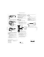
Position the securing clips as shown in Fig. 4.
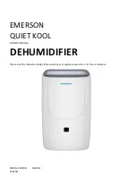
Fig. 1. Typical humidifier installation locations.
Fig. 2. HE360 Humidifier location in relation to air conditioning
cooling coils.
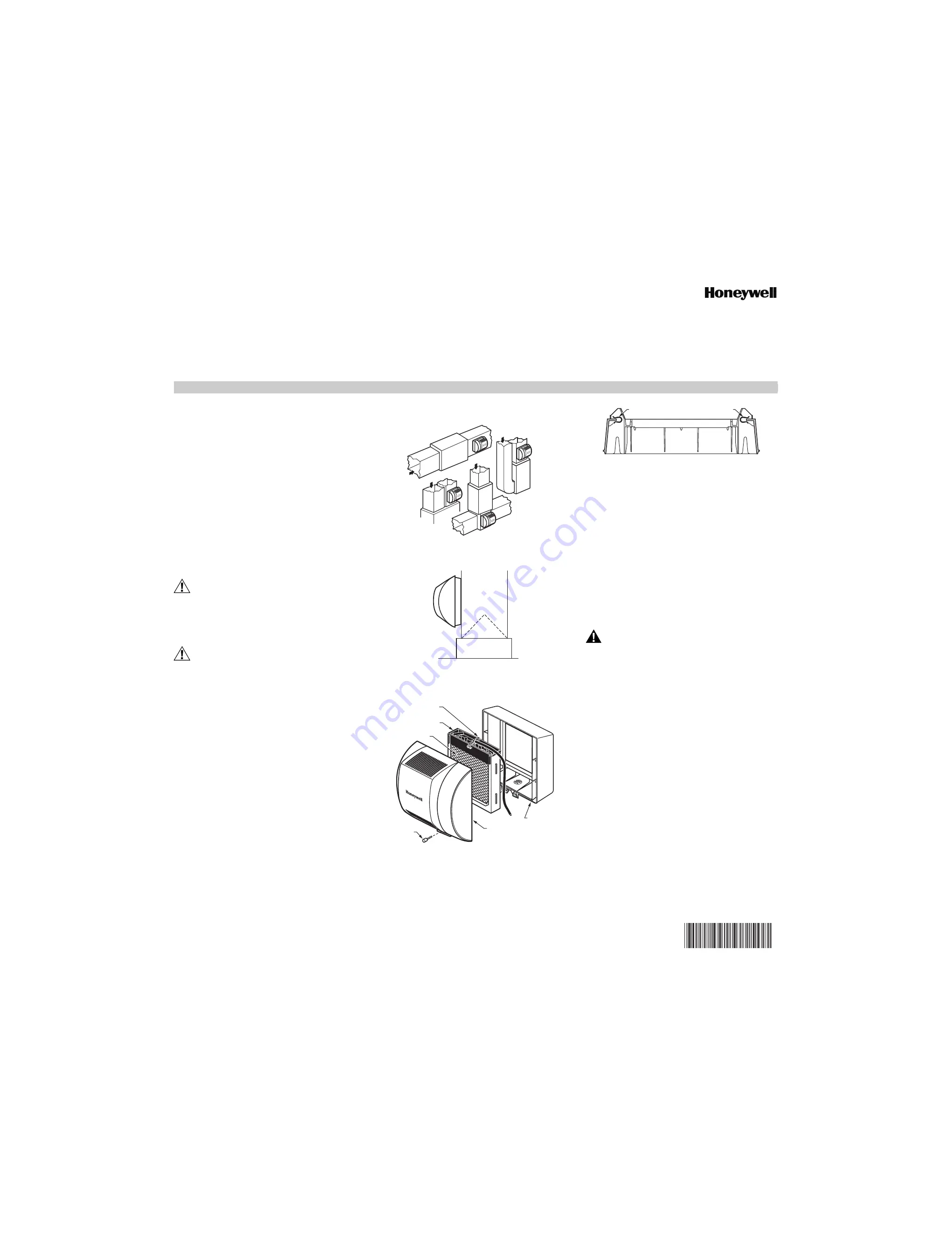
Fig. 3. Humidifier components.
Fig. 4. Position securing clips.
7.
Position the humidifier housing in the hole (be sure it is level),
so the locking tabs are in place on the upper and lower sheet
metal edge of the hole.
8.
Push in securing clips until completely seated.
9.
Drill holes and install the three sheet metal screws at the top of
the humidifier housing. Secure the housing with the three
remaining screws.
10.
Reinstall the humidifier pad assembly in the humidifier housing.
IMPORTANT
For proper operation, be sure the mark on the end of the
humidifier pad is facing up. Check that the water feed tube is
placed in the guide slots of the humidifier housing.
11.
Hook the top of the cover to the housing and secure with the
thumbscrew located at the bottom of the cover.
WIRING
WARNING
Voltage Hazard.
Moving parts can cause electrical shock and injury.
•
Disconnect power supply before installation or servicing.
•
This device contains a moving fan blade; do not operate the
humidifier without the cover securely attached.
All wiring must comply with applicable local codes, ordinances
and regulations.
For H808 Humidistat, H8908 or H908 Convertible
Humidity Control Wiring Connections:
IMPORTANT
• Select models of fan centers include humidifer taps so the
current sensing relay or sail switch is not needed.
• If not using a current sensing relay or sail switch, the 120V
humidifier plug must be energized during blower motor
cycles for proper operation.
12.
Wire the current sensing relay or sail switch.
13.
Connect only the two yellow wires to the humidistat (red wire
connections are not used for mechanical humidistats). See the
typical wiring diagrams in Fig. 5 through 7.
For additional mounting and wiring information, refer to the humidistat
installation instructions.
M12808B
HORIZONT
AL
DOW
N
FLO
LOWBOY
RETURN
RETURN
RETURN
HIGHBOY
RETURN
M12812B
M31023
COVER
ASSEMBLY
HUMIDIFIER
PAD ASSEMBLY
FEED TUBE NOZZLE
WATER
DISTRIBUTION TRAY
HUMIDIFIER
HOUSING
THUMB
SCREW
M12813A
CLIP
CLIP