background image

B

KMD 250

Multi-Function Display/GPS

Pilot’s Guide

N

Summary of Contents for KMD 250

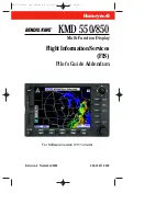
Page 1: ...B KMD 250 Multi Function Display GPS Pilot s Guide N ...

Page 2: ...o U S law is prohibited COPYRIGHT NOTICE Copyright 2003 2007 Honeywell International Inc All rights reserved Reproduction of this publication or any portion thereof by any means without the express written permission of Honeywell International Inc is prohibited For fur ther information contact Technical Publications Honeywell One Technology Center 23500 West 105th Street Olathe Kansas 66061 Teleph...

Page 3: ...KMD 250 Multi Function Display and KMD 250 Multi Function Display with GPS Software Version 02 01 or later ...

Page 4: ...R 1 Revision History and Instructions Manual KMD 250 Pilot s Guide Revision 4 August 2007 Part Number 006 18281 0000 Summary S W 02 01 Added XM functionality to the KMD 250 ...

Page 5: ...6 18281 0000 Summary S W 01 08 Added Airport Type on Airport Info Screen on page 1 25 Added TIS patent statement on inside front cover Changed Awareness to Avoidance on page 1 1 Changed 100L to 100LL on page 1 27 Added Definition for Heading on TIS screen on page 3 12 Corrections to Index pages I 1 and I 12 ...

Page 6: ... s Guide Revision 2 April 2004 Part Number 006 18281 0000 Summary Added Internal GPS Flight planning capability Nearest function User Waypoints Direct To function Quick Tuning capability Airspace Alerting Airspace depiction Waypoint Alerting Turn Anticipation ...

Page 7: ...R 4 Revision History and Instructions Manual KMD 250 Pilot s Guide Revision 1 November 2003 Part Number 006 18281 0000 Summary Change in text on Startup Caution Page ...

Page 8: ...R 5 Revision History and Instructions Manual KMD 250 Pilot s Guide Revision 0 November 2003 Part Number 006 18281 0000 Summary This is the original release of this publication ...

Page 9: ...R 6 Intentionally left blank ...

Page 10: ...TUS ICONS 1 5 STARTUP DISPLAYS 1 8 POP UP HELP DISPLAYS 1 10 POWER DOWN 1 10 DATA FIELDS 1 10 COURSE DEVIATION INDICATOR CDI 1 12 GREAT CIRCLE COURSES AND MAGNETIC VARIATION 1 14 MINIMUM ENROUTE SAFE ALTITUDE 1 14 INTERNAL GPS STATUS 1 16 QUICKTUNE 1 16 MAP OPERATION 1 17 SELECTING A MAP DISPLAY 1 18 VFR Map 1 18 IFR Map 1 19 Relative Terrain Map 1 19 Baro Correction 1 21 OBSTACLE LABELS 1 22 Tabl...

Page 11: ...RING A USER AIRPORT 1 47 EDITING A USER WAYPOINT 1 52 DELETING A USER WAYPOINT 1 53 DIRECT TO OPERATION 1 55 DIRECT TO A DATABASE OR STORED WAYPOINT 1 55 DIRECT TO USING THE JOYSTICK POINTER 1 56 OBS COURSE MODE 1 56 FLIGHT PLAN OPERATION 1 59 VIEWING THE ACTIVE FLIGHT PLAN 1 59 VIEWING FLIGHT PLAN DATA 1 60 Fuel Flow 1 61 Changing the Data Columns 1 61 CREATING A FLIGHT PLAN 1 62 ACTIVATING A STO...

Page 12: ... OBS Course Within the Active Flight Plan 1 77 TRIP PLANNING USING PRESENT POSITION 1 78 SYSTEM SETUP 1 81 MAP SETUP 1 81 NAVIGATION SETUP 1 84 DEMO MODE SETUP 1 86 Demo Mode for Non GPS Versions 1 87 Demo Mode for GPS Versions 1 88 Changing Demo Mode Settings 1 88 SOFTWARE VERSIONS 1 89 DATABASE VERSIONS 1 90 MAP DISPLAY ICONS 1 91 DATACARDS 1 95 DATA AREAS 1 95 INSERTING A NEW DATACARD 1 96 TRAN...

Page 13: ...ERT WEATHER WATCHES VDL ONLY 2 12 VALUE ADDED SERVICE WEATHER PRODUCTS 2 13 NEXRAD 2 13 NEXRAD Abnormalities 2 14 NEXRAD Limitations 2 15 Intensity 2 16 GRAPHICAL METAR 2 17 GRAPHICAL AIRMET 2 18 GRAPHICAL SIGMET 2 19 GRAPHICAL CONVECTIVE SIGMET 2 19 GRAPHICAL ALERT WEATHER WATCHES VDL ONLY 2 20 SUBSCRIPTIONS 2 21 VDL SUBSCRIPTIONS 2 21 Setting Up a VDL Subscription 2 23 Checking FIS VDL Subscript...

Page 14: ...ETS PAGE 2 40 Graphical SIGMETs Page Operational Controls 2 41 Using the Graphical SIGMETs Page 2 41 GRAPHICAL CONVECTIVE SIGMETS PAGE 2 43 Graphical Convective SIGMETs Page Operational Controls 2 44 Using the Graphical Convective SIGMETs Page 2 44 GRAPHICAL ALERT WEATHER WATCHES PAGE AWW VDL ONLY 2 46 Graphical Weather Watches Page Operational Controls 2 47 Using the Graphical Weather Watches Pag...

Page 15: ...NG METARS 2 65 UNDERSTANDING TAFS 2 68 UNDERSTANDING PIREPS 2 70 UNDERSTANDING AIRMETS 2 72 UNDERSTANDING SIGMETS 2 74 UNDERSTANDING CONVECTIVE SIGMETS 2 76 UNDERSTANDING ALERT WEATHER WATCHES AWW 2 78 SECTION 3 TRAFFIC AVOIDANCE OPERATION INTRODUCTION 3 1 TRAFFIC FUNCTION STATUS ICONS 3 2 TAS TCAS 3 3 TAS TCAS NORMAL OPERATION 3 3 OPERATIONAL CONTROLS FOR TAS TCAS 3 4 TAS TCAS SYMBOLOGY 3 5 Non T...

Page 16: ... SYMBOLOGY 3 14 Proximity Intruder Traffic 3 14 Proximity Intruder Non Altitude Reporting NAR Traffic 3 14 Traffic Advisory TA 3 14 Traffic Advisory Non Altitude Reporting NAR 3 14 Off Scale Traffic 3 14 TRAFFIC ADVISORY WHILE IN MAP DISPLAY 3 15 AUTO POP UP 3 15 VIEWING TRAFFIC IN A DATA FIELD 3 15 COAST MODE 3 16 TIS SYSTEM FAULTS 3 17 System Off 3 17 No Data Received 3 17 Transponder Not Report...

Page 17: ...N WEATHER VIEWS 4 3 SWITCH BETWEEN DISPLAY MODES 4 3 Cell Display Mode 4 3 Strike Display Mode 4 4 CHANGING DISPLAY RANGE 4 4 OPERATION IN STORMSCOPE MODE WITH FLIGHT PLAN 4 5 OPERATION IN MAP DISPLAY 4 5 SECTION 5 SYSTEM MESSAGES VIEWING SYSTEM MESSAGES 5 1 APPENDIX A DEFINITIONS ACRONYMS AND ABBREVIATIONS A 1 DEFINITIONS A 1 ACRONYMS AND ABBREVIATIONS A 2 Table of Contents viii KMD 250 Pilot s G...

Page 18: ...IATIONS B 1 APPENDIX C GPS Primer C 1 BACKGROUND C 1 GPS POSITION DETERMINING CONCEPT C 1 GPS DATA SIGNALS C 1 GPS SYSTEM SEGMENTS C 2 APPENDIX D NAVIGATION TERMS D 1 INDEX I 1 Table of Contents ix KMD 250 Pilot s Guide Rev 4 Aug 2007 ...

Page 19: ...Table of Contents x KMD 250 Pilot s Guide Rev 4 Aug 2007 Intentionally left blank ...

Page 20: ...MFD is a panel mounted Multi Function Display system that is available with an optional internal VFR GPS navigator The KMD 250 is a component of the Bendix King Integrated Hazard Avoidance System IHAS family of products that are designed to improve the pilot s ability to manage four major safety hazards situational awareness moving maps weather traffic and terrain avoidance The KMD 250 features a ...

Page 21: ...peration Explains the operation of the Flight Information Services VHF Datalink VDL or XM weather prod ucts Section 3 Traffic Avoidance System Operation Explains operation of TCAS I TCAS II and TIS sys tems as they pertain to the KMD 250 Refer to the TCAS I or TCAS II user s manual for more informa tion Section 4 WX 500 Stormscope Operation Explains operation of the Stormscope as it pertains to th...

Page 22: ...em of the Bendix King KMD 250 keeps to a minimum the number of key presses necessary to activate the various functions especially those most frequently used in the air The provision of a joy stick makes it considerably easier to operate the unit and allows for fast and efficient access to most functions 1 On Off Brightness Control 2 Function Select Keys 3 Display 4 Softkeys 5 Data Card 6 Menu Key ...

Page 23: ...nge scale one level on the displayed page Range scales on other pages will not be affected DIRECT TO NRST NEAREST KEY The Direct To Key D is found on units containing the optional internal VFR GPS navigator When pressed the Direct To function is ini tiated Direct To will only function when the internal GPS is selected as the current navigation source The NRST Nearest Key is found on units without ...

Page 24: ...Stormscope black box thunderstorm sensor When the Stormscope interface is on and the overlay is enabled lightning icons will also appear on the display DEMO MODE The Demo Mode can be used to practice using the KMD 250 This will allow you to utilize it to the maximum extent When the KMD 250 is in the Demo Mode it performs as if it is receiving adequate sensor signals to use the various functions Se...

Page 25: ...de being displayed Black on cyan Active traffic information being displayed Black on gray Traffic sensor in standby mode not being displayed Black on gray Traffic sensor active not being displayed Black on yellow TIS service not available Flashing black on yellow A Traffic Advisory TA alert is active The icon will be flashing Flashing black on red A Resolution Advisory RA alert is active The icon ...

Page 26: ...ignal is weak Black on a cyan background Weather data is currently being received from a signal and displayed on the pre sent page XM signal is marginal Black on a cyan background Weather data is currently being received from a signal and displayed on the pre sent page XM signal is good Black on gray Weather data not being received nor dis played on the present page Black on gray Weather data is c...

Page 27: ...f Stormscope is installed with the system a display similar to the one at the right will be seen After the completion of the Self Test press the OK Softkey One of the following Instrument Panel Self Test Pages will be displayed depending on whether the unit is equipped with an internal GPS or is the non GPS version Non GPS KMD 250 KMD 250 with Internal GPS ...

Page 28: ...f the KMD 250 is configured to use the optional internal GPS as sole source or backup verify the Course Deviation Indicator CDI is showing half scale right deflection with a FROM indication If all is correct after verification press the OK Softkey One of the following caution screens will now be displayed depending on whether the unit is the non GPS version or the unit is equipped with the interna...

Page 29: ...stem will shut down in 5 seconds This allows for inad vertently turning off the system Push the ON OFF Brightness Control back in before the count down is over and the system will continue where it left off with no loss of data DATA FIELDS Data Fields may be used to display various types of information in win dows on the left side of the screen as shown here This makes it easy to get quick access ...

Page 30: ... Map Display Data Fields Off Map Display Data Fields On ALT Altitude BRG Bearing to Waypoint CDI Course Deviation Indicator DIS Distance to Waypoint DEP TIME Departure Time DTK Desired Track ESA En Route Safe Altitude ETA WPT Estimated Time of Arrival at Waypoint ETE WPT Estimated Time Enroute to Waypoint FLT TIME Flight Time GNDSPD Ground Speed HEADING Heading MSA Minimum Safe Altitude NEAR POS N...

Page 31: ...display Figure 1 2 If the Data Fields were on to begin with a FIELDS OFF Softkey will be available If the Data Fields were off a FIELDS ON Softkey will be available Pressing this Softkey will toggle the Data Fields on and off 3 When finished press the DONE Softkey To change Data Fields perform the follow steps 1 Perform steps 1 and 2 above With the Data Fields turned on use the Joystick to select ...

Page 32: ...ts one nautical mile deviation from the desired track full scale deviation is 5 NM Different CDI scales can be set on the Navigation Setup Page A vertical deviation bar positioned two dots to the right of the center triangle indicates the aircraft is two nautical miles to the left of course as shown in Figure 1 5 The center triangle also serves as the CDI s TO FROM indicator and operates in the sa...

Page 33: ...enerally bearing not radial will be used when long distances are involved MINIMUM AND ENROUTE SAFE ALTITUDE The Minimum Safe Altitude MSA displayed is the altitude defined by Jeppesen as Grid Minimum Off Route Altitude Grid MORA This alti tude is derived by Jeppesen for sectors which are one degree of latitude by one degree of longitude in size One degree of latitude is 60 nautical miles One degre...

Page 34: ...01 feet MSL or higher The KMD 250 displays dashes for areas outside the database coverage area or for areas where the Grid MORA is not defined The Enroute Safe Altitude ESA is the highest MSA sector altitude from the present position to the active waypoint then to the destination way point along the active flight plan See Figure 1 9 When the KMD 250 is in the OBS Course Mode the minimum en route s...

Page 35: ...Figure 1 10 2 Press the AUX MENU Softkey to display Figure 1 11 3 Using the Rotary Knob or the Joystick to select Internal GPS Status as shown in Figure 1 11 4 Press the SELECT Softkey to display Figure 1 12 5 Press the RCVR INFO Softkey to view information such as the GPS receiver software part number software version soft ware revision and serial number as shown in Figure 1 13 QUICKTUNE The KMD ...

Page 36: ...WPT XTK 3 North Pointer 4 Aircraft Symbol Indicates present position Stylized airplane when heading or track input is present a plus symbol with no heading or track 5 Range Rings Outer ring radius is selected range inner ring radius is one half the selected range 6 RESET STICK Soft Label 7 Traffic Symbol Overlay Displayed when traffic avoidance system is installed 8 Graphical METAR Icon Overlay Di...

Page 37: ...titude See Tables 1 1 and 1 2 on Absolute and Relative Altitudes VFR MAP With the VFR Map displayed topographic data is displayed as colors corresponding to the absolute altitude stored in the database see Figure 1 14 The VFR Map displays terrain similar to a VFR sectional chart Table 1 1 shows the levels and terrain shading used on the VFR Map A color key can be displayed by moving the Joystick P...

Page 38: ...aircraft s present altitude as shown in Figure 1 17 This feature is useful in providing awareness to possible terrain hazards at the present aircraft altitude Table 1 2 shows the levels and terrain shading used on the Relative Terrain Map Figure 1 16 IFR Map Figure 1 17 Relative Terrain Map Absolute Terrain Altitude feet Color 13000 Dark Brown 11500 12999 10000 11499 9000 9999 8000 8999 7000 7999 ...

Page 39: ...on the Relative Terrain Map Note the differences in color between terrain and obstacles based on an aircraft altitude of 2 000 ft MSL Obstacles are enhanced on the Relative Aircraft Altitude Relative to Terrain feet Aircraft Altitude Relative to Obstacle feet Color 250 ft or more below sur rounding terrain 250 ft or less above obstacle Between 249 ft below 250 ft above surrounding terrain Between ...

Page 40: ...rmined at installation If no altitude information is received a cau tion will be displayed as in Figure 1 21 NOTE If a baro corrected or pressure altitude source is used the Relative Terrain Map may not display colors accu rately in operations above 18 000 feet when the altimeter setting is 29 92 in Hg Baro Correction If the altitude information source is Gillham pressure alti tude then a baro cor...

Page 41: ...U Softkey to display Figure 1 24 Use the Joystick to select Baro Entry as shown 3 Press the SELECT Softkey and Figure 1 25 will be displayed 4 Turn the Rotary Knob to select the desired entry 5 Press the OK Softkey OBSTACLE LABELS Obstacles are labeled with two numbers The first number is the height of the obstacle in FEET ABOVE MSL The second number in brackets is the height of the obstacle in FE...

Page 42: ...ay The displayed data is updated every second Press the RNG Δ Δ range up or RNG range down key at any time to zoom the map in and out to whichever one of the twelve pre set scales desired The available range settings are 1 2 5 5 10 15 20 30 50 100 150 200 300 500 and 1000 nm The levels of detail appearing at each zoom level can be changed in the Map Setup menu See Map Setup When active Auto Zoom a...

Page 43: ... This function can be used to measure dis tance and bearing to any point on the map The window formed by the extremities of the display can be moved panned around the map by bumping the display borders left right up or down with the pointer The RNG Δ Δ and RNG keys can still be used to zoom the map in and out Press RESET STICK and the joystick pointer will vanish the display will return to the mov...

Page 44: ...f the airport identifier KOSH The airport type is either MILITARY PRIVATE or blank for others public The airport elevation 808ft is shown to the right of the air port type Runway orientation and lengths are displayed to the right of the airport dia gram Runway surfaces are shown as an H for hard and an S for soft Lighting is shown as an L for lit and a U for unlit Pressing the NEXT Softkey will di...

Page 45: ...e selected frequency Use the Joystick or Rotary Knob to place the cursor over the desired fre quency in the list If the system contains only one KX 155A 165A simply pressing the QUICK TUNE Softkey will tune the Nav Comm to the selected frequency If multiple KX 155A 165A systems are contained in the installation pressing the QUICK TUNE Softkey will display the Nav or Comm selection display as shown...

Page 46: ...ed in this field NO APR No approaches are available NP APR Non precision approach available MLS MLS approach available ILS ILS approach available ILS MLS ILS and MLS approaches available 4 GPS Approach Availability If an approved non precision GPS approach is available GPS will be displayed 5 Comm Frequency List Lists the available communications frequencies for the airport being displayed See App...

Page 47: ...r Comm for tuning Press the OK Softkey to tune the radio AIRSPACE INTERROGATION In order to interrogate a piece of airspace on the Map display move the joystick pointer to one of the airspace boundaries to display an information window as shown in Figure 1 39 IMPORTANT When a single airspace boundary line is shared by two different pieces of air space which is very common the airspace with the low...

Page 48: ...tary Knob to select the desired Comm for tuning Press the OK Softkey to tune the radio AIRSPACE ALERTING The Special Use Airspace SUA alert feature is three dimensional The SUA areas are stored in the KMD 250 database with regard to altitude when the actual SUA altitude limitations are charted in terms of mean sea level MSL However if the actual lower limit of an SUA is charted in terms of an alti...

Page 49: ...alert feature may be disabled or enabled on the Navigation Setup Page See Navigation Setup later in this section If the SUA alert feature has been enabled the KMD 250 allows selection of a vertical buffer on the in order to provide an additional layer of protec tion from inadvertently entering an SUA The vertical buffer serves to stretch the SUA area in both directions up and down by the selected ...

Page 50: ...age is given MESSAGE PRESS MENU will flash at the bottom of the display as shown in Figure 1 43 Pressing the MENU Key will display the message as shown in Figure 1 44 Press the OK Softkey to exit the message To enable or disable SUA Alerting perform the following 1 Press the MENU Key Press the AUX MENU Softkey to display Figure 1 45 2 Use the Rotary Knob or the Joystick to place the cursor over Na...

Page 51: ... will be editable Use the Joystick to place the cursor over this field see Figure 1 48 and use the Rotary Knob to select the desired altitude An Airspace Alert message will be given when the aircraft enters within this selected buffer altitude from the published SUA alti tude boundary For example if the published upper SUA boundary is 3 000 feet and a buffer altitude of 1 000 feet is selected the ...

Page 52: ...s i e DME arcs procedural turns and holds most GPS units stop outputting flight plan data but continue to output positional data During a DME arc or procedural turn the KMD 250 will continue to show position track and ground speed but the curved line depicting the arc or turn will not be displayed In OBS mode some GPS units will not be able to provide flight plan data Present position is still pro...

Page 53: ... Softkey On the first press the land data will be removed from the display as seen in Figure 1 52 Notice roads railways city icons etc are no longer dis played Note also that a L is now shown in the bottom left of the screen indicating the dis play is minus land data 3 Press the DECLUTTER Softkey again On the second press the aeronautical data will be removed from the display as seen in Figure 1 5...

Page 54: ...on or user entered waypoint closest to the aircraft s present position Up to 20 of the find criteria may be listed and must be within 200nm of the air craft s position The closest will be listed first the furthest listed last 1 Press the NRST Key to display the FIND NEAREST display as shown in Figure 1 55 In this case a list of air ports is displayed 2 If more information on a particular airport i...

Page 55: ... over the desired Find type 5 Press the OK Softkey 6 If Airports is selected as the type as in Figure 1 57 pressing the AIRPORT FILTER Softkey Figure 1 58 will display the AIRPORT FILTER CRITERIA Window as shown in Figure 1 59 7 The listed airports can be filtered by runway length and runway type Use the Joystick to place the cursor over the desired field and use the Rotary Knob select the the des...

Page 56: ...but is displaying information coming from an external GPS source Figure 1 60 will be displayed This is a prompt to indicate the Direct To function is not available when using an external GPS source However this will not affect the Find Nearest feature Press the OK Softkey to display the FIND NEAREST display The Find Nearest feature is now used as discussed previously If the KMD 250 is presently na...

Page 57: ...int Alert If an external Waypoint Alert annunciator is installed in the aircraft it will also flash TURN ANTICIPATION When Turn Anticipation is enabled in Navigation Setup it will provide turn guidance to a new course for intercepting the next leg of the flight plan Waypoint Alerting will begin when the estimated time to the start of the turn is about 20 seconds As previously dis cussed the Waypoi...

Page 58: ...e turn transition to the next leg in the flight plan at the very beginning of the computed turn point Upon reaching this computed turn point the Waypoint Alert annunciator will stop flashing and remain on steadily while the text TURN TO is dis played as shown in Figure 1 65 If an autopilot is engaged this is the time to change the selected course on the CDI or HSI to that indicated next to TURN TO...

Page 59: ...1 40 KMD 250 Pilot s Guide Section 1 Basic Operation Rev 2 Apr 2004 Intentionally left blank Map Operation ...

Page 60: ...s may be entered in place of the default 2 1st Remarks Field The default entry is current date This field may be cleared and any combination of up to 24 alphanumeric and punctuation characters may entered 3 2nd Remarks Field The default entry is current time This field may be cleared and any combination of up to 24 alphanumeric and punctuation characters may entered 4 Waypoint Latitude Longitude I...

Page 61: ...Press the AUX MENU Softkey to display Figure 1 67 Use the Joystick or Rotary Knob to place the cursor over User Waypoints as seen in Figure 1 67 2 Press the SELECT Softkey to display the USER WAYPOINT LIST display as shown in Figure 1 68 Initially the list will be empty As way points are entered the list will be populated User Waypoints Figure 1 68 Figure 1 66 Figure 1 67 ...

Page 62: ...n the Rotary Knob one increment and the first character will be highlighted as in Figure 1 70 If the desired identifier is less than six char acters press the CLEAR IDENT Softkey to clear the IDENT field Otherwise turn the Rotary Knob to enter the desired first character Use the Joystick to go to the next field and again use the Rotary Knob to enter the next desired char acter and so on until comp...

Page 63: ... the CLEAR TEXT Softkey Repeat steps 7 and 8 until all the desired char acters are entered see Figure 1 74 11 The default waypoint POSITION is the aircraft posi tion at the time the USER WAYPOINT EDIT display was selected The latitude and longitude of the waypoint is displayed As the aircraft con tinues moving the Present Position is indicating the current bearing and distance to the waypoint posi...

Page 64: ...e bearing and dis tance from a known position such as an airport or navaid This is done by first using the Joystick to place the cursor over Present Position as shown in Figure 1 75 Turn the Rotary Knob one increment to display the WAYPOINT ENTRY window as shown in Figure 1 76 14 Use a combination of the Joystick and Rotary Knob as previously discussed to enter the desired identifier of the air po...

Page 65: ...TRY Page Note that the KMD 250 has also computed the latitude longitude for the waypoint 20 Press the SAVE EXIT Softkey Also if a waypoint is defined by entering the latitude longitude and an airport or navaid identi fier is then entered the KMD 250 will compute the bearing and distance of the waypoint from the selected airport or navaid After the waypoints are saved the User Waypoint List is dis ...

Page 66: ...er Airport Edit display 2 Runway Orientation Selectable from 01 19 through 18 36 3 Runway Surface Type Hard or Soft can be selected 4 Comm Frequecy Type One of 33 abbreviations may be selected in each of two fields See Appendix A for abbreviations 5 Comm Frequecies Any valid 8 33 kHz or 25 kHz communication frequency in each of two fields 6 Runway Elevation The runway elevation can be entered from...

Page 67: ... display USER AIRPORT 2 of 2 as shown in Figure 1 83 The cursor will be initially be placed in Runway orientation field and the default will be None 4 Turn the Rotary Knob to enter the desired runway orien tation Values of 01 19 through 18 36 may be entered as seen in Figure 1 84 Note that when a value entered the airport icon now reflects a runway with the entered orientation User Waypoints Figur...

Page 68: ... reflect a hard surface runway 7 Use the Joystick to place the cursor in the runway Length field Use the Rotary Knob to select the desired runway length A value from 0 to 20 000 feet can be entered Note that 2000 ft has been entered in Figure 1 87 8 Use the Joystick to place the cursor in the runway eleva tion Elev field Use the Rotary Knob to select the desired runway elevation A value from 2000 ...

Page 69: ...1 88 10 Turn the Rotary Knob to select the desired the fre quency type as shown in Figure 1 89 See Table 1 3 for a list of possible Type entries 11 In a similar manner as pre viously discussed use the Joystick and the Rotary Knob to enter the desired frequen cies in the appropriate Freq fields as seen in Figure 1 90 12 When all desired entries are completed press the SAVE EXIT Softkey User Waypoin...

Page 70: ...val AWOS Automated Weather Observation System ASOS Automated Surface Observation System CTA Control Area VFR frequency used outside U S DIR Director approach control radar TMA Terminal Area VFR frequency used outside U S RDR Radar Only Frequency RDO Radio AAS Aeronautical Advisory Service AFIS Aerodrome Flight Information Service ATF Aerodrome Traffic Frequency CTAF Common Traffic Advisory Frequen...

Page 71: ...display Figure 1 91 Press the AUX MENU Softkey to display Figure 1 92 Use the Joystick or Rotary Knob to place the cursor over User Waypoints as seen in Figure 1 92 2 Press the SELECT Softkey to display the USER WAYPOINT LIST display as shown in Figure 1 93 Use the Rotary Knob and Joystick to select waypoint to edit 3 Press the EDIT WPT Softkey to display the USER WAYPOINT EDIT 4 Repeat steps 3 th...

Page 72: ...he following steps 1 Perform steps 1 and 2 in Editing A User Waypoint 2 Press the DELETE WPT Softkey Figure 1 94 will now be displayed 3 Press the OK Softkey to complete the deletion NOTE Waypoints that are part of a flight plan denoted by the lock symbol in the User Waypoint List cannot be deleted until removed from the flight plan User Waypoints Figure 1 94 ...

Page 73: ...1 54 Rev 2 Apr 2004 KMD 250 Pilot s Guide Section 1 Basic Operation User Waypoints Intentionally left blank ...

Page 74: ...ernal navigation source DIRECT TO A DATA BASE OR STORED WAYPOINT 1 If there is no active flight plan pressing the Direct To Key will display Figure 1 95 2 Turn the Rotary Knob to display the Waypoint Entry Page as shown previously in Figure 1 76 The desired desti nation can be entered here by using the Rotary Knob as dis cussed previously 3 Press the OK Softkey to enter the destination in the DIRE...

Page 75: ... will appear in the DIRECT TO field This way point will be placed on the map at the position of the Joystick Pointer To change the way point name see the discussion on User Waypoints earlier in this section 3 Press the ACTIVATE Softkey and the route will be displayed on the Map as shown in Figure 1 100 OBS COURSE MODE The Direct To function also allows an OBS course to be navigated to the selected...

Page 76: ...er to enter a new destina tion Turn the Rotary Knob to display the WAYPOINT ENTRY window 4 Press the ACTIVATE Softkey and the route will be displayed on the Map as shown in Figure 1 103 NOTE When OBS Mode is active pressing the Direct To Key will display the active OBS COURSE window To change the OBS course to a Direct To route press the the Direct To Key to display Figure 1 102 Press the DIR TO S...

Page 77: ...1 58 Rev 2 Apr 2004 KMD 250 Pilot s Guide Section 1 Basic Operation Direct To Operation Intentionally left blank ...

Page 78: ...ress the FPL Key to display the ACTIVE FLIGHT PLAN Page as shown in Figure 1 104 If the KMD 250 does not have the optional internal GPS the DONE and DELETE WPT Softkeys will not be available The active leg and waypoint are shown in magenta When Auto Leg Sequencing is enabled after passage of the active waypoint the KMD 250 will automatically sequence to the next waypoint in the flight plan The nex...

Page 79: ...Press the RESET STICK Softkey to exit Joystick Pointer operation If applicable press the MORE INFO softkey to view more information about the selection In the case of an airport pressing the NEXT softkey on the AIRPORT INFO 1 of 2 Page will display the AIRPORT INFO 2 of 2 and allow access to the QUICK TUNE Softkey Pressing this softkey will tune the radios to the correct frequencies for the airpor...

Page 80: ... COLUMNS The three data columns can be changed to reflect various types of information for each leg To change the columns perform the following steps 1 Press the CHANGE FIELDS Softkey to display Figure 1 109 2 Move the Joystick horizon tally to select the desired data column in this case the first column 3 Turn the Rotary Knob to select one of the available options from the list Each field can be ...

Page 81: ...display will appear as shown in Figure 1 110 2 Press the NEW FPL Softkey to display the STORED FLIGHT PLAN Page as seen in Figure 1 111 The first way point in the flight plan can be entered using the Joystick Pointer and selecting a point on the map or by entering an identifier To enter an identifier turn the Rotary Knob and the WAYPO INT ENTRY window will be dis played as in Figure 1 112 Use the ...

Page 82: ... STICK Softkey Using the Joystick move the pointer to the desired place on the map as in Figure 1 114 Press the INSERT WPT Softkey to enter the waypoint in the list 3 Continue entering way points using either method until the flight plan is complete Press the DONE Softkey and the flight plan will be entered on the FLIGHT PLAN INDEX Page as shown in Figure 1 115 Flight Plan Operation Figure 1 113 F...

Page 83: ... A STORED FLIGHT PLAN Perform the following steps to activate a flight plan that has been stored in the KMD 250 1 Press the FPL Key to dis play the FLIGHT PLAN INDEX Page as seen in Figure 1 118 Note that the current active flight plan is displayed in magenta with an arrow at the top of the list stored flight plans 2 Use the Joystick to select the desired flight plan in the list Flight Plan Operat...

Page 84: ...Softkey to use the selected flight plan If desired the selected flight plan can be navigated in reverse by pressing the INVERT Softkey The selected flight plan will now be displayed on the ACTIVE FLIGHT PLAN Page as in Figure 1 120 5 Press the DONE Softkey to return to the FLIGHT PLAN INDEX Page Flight Plan Operation Figure 1 119 Figure 1 120 ...

Page 85: ...ng discussions Pressing the COPY Softkey will allow the selected flight plan to be copied for editing while not changing the original DELETING A WAYPOINT IN THE FLIGHT PLAN To delete a waypoint in the flight plan perform the fol lowing steps 1 Use the Joystick to select the waypoint to be deleted in list on the left of the display 2 Press the DELETE WPT Softkey to display Figure 1 123 Press the OK...

Page 86: ... after in this case OTM as shown in Figure 1 124 2 Select the new waypoint with one of the following methods To enter an identifier turn the Rotary Knob and the WAYPO INT ENTRY window will be dis played as in Figure 1 125 Use the Rotary Knob to enter the desired waypoint KTVK in the same manner as discussed in previous procedures Press the OK Softkey and the way point is entered before OTM as show...

Page 87: ... on the map as in Figure 1 127 Press the INSERT BEFORE or INSERT AFTER Softkey to enter the waypoint before or after the waypoint selected in the list as seen in Figure 1 128 3 Press the RESET STICK Softkey and the new waypoint will be displayed in the flight plan as in Figure 1 129 4 Press the DONE Softkey to return to the FLIGHT PLAN INDEX Page Flight Plan Operation Figure 1 127 Figure 1 128 Fig...

Page 88: ...o the left with the first character highlighted as in Figure 1 131 3 Use the Rotary Knob to enter the desired first character for the new waypoint name 4 Use the Joystick to select the next character field 5 Use the Rotary Knob to enter the next desired char acter for the new waypoint name Continue until the desired name is entered as seen in Figure 1 132 Pressing the DEFAULT NAME Softkey will cau...

Page 89: ...f flight plans as shown in Figure 1 134 DELETING A STORED FLIGHT PLAN To delete a flight plan perform the following steps 1 Press the FPL Key until the FLIGHT PLAN INDEX Page is displayed as shown in Figure 1 134 2 Use the Joystick to select the flight plan name 3 Press the DELETE Softkey and Figure 1 135 will be displayed 4 Press the OK Softkey and the flight plan will be deleted Flight Plan Oper...

Page 90: ...Figure 1 137 will be dis played to verify the deletion of the active flight plan 3 Press the OK Softkey to delete the active flight plan As shown in Figure 1 138 the active flight plan is no longer displayed Note also that the previously active flight plan has not been deleted from the list of stored flight plans NOTE If the active flight plan has not been stored prior to deleting press the COPY S...

Page 91: ...hese way points will be bypassed If a Direct To is established to a waypoint not in the flight plan the navigation of the active flight plan will not resume after the Direct To waypoint is reached NOTE Remember the internal GPS of the KMD 250 is not certified for IFR operation Navigation of ATC clearances on the KMD 250 can only be done as a backup to the primary navigation system PROCEEDING DIREC...

Page 92: ...c leg within an active flight plan perform the following steps 1 Press the Direct To Key to display the Direct To window as shown previously in Figure 1 139 2 Press the Direct To Key a second time to display Figure 1 142 3 Use the Joystick to scan the flight plan legs 4 When the desired leg is displayed press the ACTI VATE Softkey and the Map will again be displayed as in Figure 1 143 Note the air...

Page 93: ...e flight plan as seen in Figure 1 140 perform the following steps 1 Press the Direct To Key to display Figure 1 144 2 Press the DELETE DIRECT Softkey to display Figure 1 145 3 Press the OK Softkey The Map will again be dis played with guidance to inter cept and resume the active flight plan as shown in Figure 1 146 Flight Plan Operation Figure 1 145 Figure 1 146 Figure 1 144 ...

Page 94: ...rse If waypoints exist in the flight plan prior to that which the OBS Course is established these waypoints will be bypassed If an OBS Course is established to a waypoint not in the flight plan the navigation of the active flight plan will not resume after the waypoint is reached SETTING AN OBS COURSE TO AN ACTIVE FLIGHT PLAN WAYPOINT To set an OBS Course to a waypoint within an active flight plan...

Page 95: ...y Knob to select Enabled With Auto Leg Sequencing enabled the remaining portion of the flight plan will automatically resume after passing the waypoint 6 Press the ACTIVATE Softkey to start navigating the OBS Course The selected course will be displayed as the active portion of the flight plan as seen in Figure 1 150 Flight Plan Operation Figure 1 149 Figure 1 150 ...

Page 96: ...n active flight plan as seen in Figure 1 150 per form the following steps 1 Press the Direct To Key to display Figure 1 151 2 Press the DELETE DIRECT Softkey and Figure 1 152 will be displayed 3 Press the OK Softkey to confirm the deletion The map will now display the active flight plan in Leg Mode as shown on Figure 1 153 Flight Plan Operation Figure 1 151 Figure 1 152 Figure 1 153 ...

Page 97: ...sce nario and using the data view of the Active Flight Plan Page and selecting the desired data columns to present the needed information The following example illus trates checking time distance and required fuel to KDSM while navigating a flight plan from KIXD to KOSH as shown on Figure 1 154 1 Perform the following steps to create a new flight plan as previously discussed 2 Enter the desired de...

Page 98: ...nserting the aircraft s present position in the flight plan is just like inserting any other way point in the flight plan except the position continually updates Note the ground speed and fuel flow values shown in Figure 1 159 indicate actual values by being displayed in white Fuel flow is taken from a fuel flow monitor and GPS ground speed is being used 7 If desired press the CHANGE FIELDS Softke...

Page 99: ...to the actual GPS ground speed as shown in Figure 1 161 Note also that the ETA and FUEL values have also returned to actual values Fuel flow FFLOW values can be changed in the same manner as ground speed Fuel flow and ground speed can also be changed in conjunction with one another to work out different scenarios NOTE If the KMD 250 is not interfaced with a functioning fuel flow mon itor the fuel ...

Page 100: ...rientation Set either in Track Up North Up or Heading Up Extended TRK Turns on or off the extended track line which is drawn ahead of the present position in the direction of the present track Range Rings Turns range rings on or off on the map Airport Settings Selectable airport filtering for display on the map Min Rwy Len Minimum Runway Length allows the display of airports on the map based on mi...

Page 101: ... to change the setting 3 Press the NEXT GROUP Softkey to display the AVIATI ON LINE GROUP Page as in Figure 1 165 VFR Map aviation related lines are shown with corresponding definitions The database filters airspace first by class then by type If the class is not known and the type does not fit into one of the categories it will be displayed as Unknown Other SUA types are Radar Area Alert Caution ...

Page 102: ...s in Figure 1 168 Overlay icons are shown with corresponding definitions NOTE Some functions may not be available in certain installations Unavailable functions will appear gray with dashes for values and will not be selectable If Stormscope a Traffic Avoidance System and or Flight Information Services have been installed control of how the data is displayed or not displayed on the map is accompli...

Page 103: ...50 is installed to function with an external GPS source such as a KLN 94 and KMD 250 has the optional internal GPS the system is capable of automatically switching from the external GPS source to the internal GPS when situations dictate When AutoNav is enabled this allows the system to prompt the user for a change in navigation source if valid position data is not being received from the external ...

Page 104: ...tral Daylight Time UTC 5 MST Mountain Standard Time UTC 7 MDT Mountain Daylight Time UTC 6 PST Pacific Standard Time UTC 8 PDT Pacific Daylight Time UTC 7 AKS Alaska Standard Time UTC 9 AKD Alaska Daylight Time UTC 8 HAS Hawaii Standard Time UTC 10 HAD Hawaii Daylight Time UTC 9 SST Samoa Standard Time UTC 11 SDT Samoa Daylight Time UTC 10 LCL Local Time User entered in 1 2 hour increments Magneti...

Page 105: ...he features of the KMD 250 is to use it s built in Demo Mode When the KMD 250 is in the Demo Mode it performs as if it is receiving adequate sensor signals to use the various functions Units without the optional internal GPS a pre programmed flight plan determined by the database type being used can be navi gated Units containing the optional internal GPS can navigate any user programmed waypoints...

Page 106: ...the three different types of data cards as shown in Table 1 4 In this example the AMR data base is installed therefore Figure 1 175 shows the pre programmed flight plan for KIXD to KOSH The system defaults for Demo Mode will automatically start the demo at the beginning way point for the flight plan stored in the data card The simulated flight will be at an altitude of 2000 feet and groundspeed wi...

Page 107: ...7 If necessary use the Joystick to highlight Demo Mode Setup as shown 3 Press the SELECT Softkey to display Figure 1 178 In ver sions without the optional internal GPS the default Mode setting is Auto When Auto is selected all other parameters will be grayed out To change the other parameters turn the Rotary Knob to select Manual in the Mode field The Joystick may now be used to select the desired...

Page 108: ...d by per forming the following steps 1 Press the MENU Key to dis play the AUX MENU Softkey as in Figure 1 176 2 Press the AUX MENU Softkey to display Figure 1 179 If necessary use the Joystick to highlight Software Versions as shown 3 Press the SELECT Softkey to display Figure 1 180 System Setup Figure 1 180 ...

Page 109: ...play Figure 1 181 If necessary use the Joystick to highlight Database Versions as shown 3 Press the SELECT Softkey to display Figure 1 182 NOTE For a VDL installation if a new datacard is not installed before the date shown under SUBSCRIPTION DATA the KMD 250 will no longer receive FIS subscriptions even if the FIS subscriptions are cur rent A new datacard is only required on initial XM installa t...

Page 110: ...1 91 Rev 2 Apr 2004 KMD 250 Pilot s Guide Section 1 Basic Operation MAP DISPLAY ICONS The following table shows the map display icons and their meanings Map Display Icons ...

Page 111: ...1 92 Rev 2 Apr 2004 KMD 250 Pilot s Guide Section 1 Basic Operation Map Display Icons ...

Page 112: ...1 93 Rev 2 Apr 2004 KMD 250 Pilot s Guide Section 1 Basic Operation Map Display Icons ...

Page 113: ...1 94 Rev 2 Apr 2004 KMD 250 Pilot s Guide Section 1 Basic Operation Map Display Icons ...

Page 114: ...h reso lution Also included is a low resolution map of the rest of the world The ten ICAO ARINC areas along with their three letter identifiers are AFR Africa CAN Canada EEU Eastern Europe EUR Europe LAM Latin America MES Middle East PAC Pacific SAM South America SPA South Pacific USA USA These areas are combined to produce three data cards covering the entire world that contain the following data...

Page 115: ...sh in the datacard until it clicks then release The data card should now slide straight out 3 With the new card facing upward as indicated on it s label insert the new datacard until it clicks The new data card is now locked in place 4 Turn the unit on and if necessary wait for the new software to load 5 Figure 1 183 will be dis played to allow flight plans and waypoints stored on the previous dat...

Page 116: ...d data such as flight plans and waypoints can be moved between datacards The following displays depict those seen on a KMD 250 con taining the internal GPS STORE CURRENT USER DATA ON ANOTHER DATA CARD To move from one datacard to another perform the following steps 1 Press the MENU Key 2 Press the AUX MENU Softkey to display Figure 1 187 Use the Joystick to high light User FPL Save Load as shown 3...

Page 117: ... the original data card NOTE In units that do not con tain the internal GPS refer ences to flight plans will not be displayed For example the title of the window in Figure 1 190 will be USER WAYPOINT DATA STORED RETRIEVE USER DATA FROM ANOTHER DATA CARD To move from one datacard to another perform the following steps 1 Press the MENU Key 2 Press the AUX MENU Softkey to display Figure 1 191 Use the...

Page 118: ...193 is dis played insert the datacard containing the data to be copied 7 After the datacard is inserted the data will be read and Figure 1 194 will displayed indicating the data is ready to be copied 8 Re insert the original data card that will receive the data 9 Figure 1 195 will be dis played indicating data on the datacard will be overwritten 10 Press the OK Softkey to overwrite Datacards Figur...

Page 119: ...days As a registered owner of a KMD 250 you will be offered a 1 3 6 12 monthly datacard subscription DATABASE CYCLE INFORMATION Keeping the database current in the KMD 250 is the user s responsibility Honeywell maintains its VDL databases to be current at all times to the latest Jeppesen 28 day data cycle For VDL database subscriptions and FIS subscriptions contact Wingman Services at the followin...

Page 120: ... 7 days week Two dif ferent systems are available for delivery of the weather data a ground based VHF Datalink VDL network and Baron WxWorx weather deliv ered via the XM Radio satellite system Data acquired from FAA approved weather sources is processed and then distributed to VDL Ground Stations and to the XM satellite network The Ground Stations broadcast the information over a VHF Data Link VDL...

Page 121: ...ne of sight range increases with altitude However there is no appreciable increase in coverage above 17 500 ft MSL The following illustration shows how altitude influ ences FIS VDL coverage The following diagram illustrates how XM Wx data is received in the air craft The XM Satellite Radio weather system provides continuous coverage down to ground level over the entire continental United States A ...

Page 122: ...st once every 5 minutes by the VDL system Products are broadcast once every 5 12 minutes depending on the product by the XM system NOTE Due to inherent delays areas of coverage and relative age and availability of the data that can be experienced weather data cannot be viewed as an absolute depiction of conditions at a specific location Introduction No Cost VDL Subscription Fee Based XM Subscripti...

Page 123: ...rategic planning tool for pilot decisions on avoiding inclement weather areas that are beyond visual range or where poor visibility precludes visual acquisition of inclement weather Datalink weather information may be used as follows a To aid the pilot in situational awareness of hazardous meteo rological conditions b As a cue to the pilot to communicate with the ATC controller AFSS specialist Ope...

Page 124: ...ng displayed on the present page Black on a cyan background Weather data is currently being received from a signal and displayed on the pre sent page XM signal is weak Black on a cyan background Weather data is currently being received from a signal and displayed on the pre sent page XM signal is marginal Black on a cyan background Weather data is currently being received from a signal and display...

Page 125: ...2 6 KMD 250 Pilot s Guide Section 2 FIS Operation Rev 4 Aug 2007 Intentionally left blank Introduction ...

Page 126: ... and time of issue 4 Modifier AUTO if automated report or COR if corrected observation 5 Wind 6 Visibility 7 Runway visual range as required 8 Weather phenomena 9 Sky condition 10 Temperature dew point group 11 Altimeter 12 Remarks as required METARs available within the selected range of the selected area will be displayed up to a maximum of 25 reports These reports are displayed in an encoded te...

Page 127: ...n of a ceiling below 3 000 feet Also new formation of cloud layers or other obscuring phenomenon that occur below 1 000 feet 7 Aircraft mishaps 8 Other meteorological conditions that the agency or the observer determine as critical Refer to the section on METARs for an explanation of the elements The element sequence and content will be the same as those in a METAR report with the exception of the...

Page 128: ...ated TAF is no longer transmitted See the section on Understanding Textual Aviation Weather Reports for instructions on decoding textual TAFs PIREP VDL ONLY A PIREP Pilot Weather Report is an observation of conditions at a spe cific location or along a specific route These conditions are reported by pilots when communications are established with ground facilities such EFAS AFSS FSS ARTCC or ATC A...

Page 129: ... winds icing and freezing levels AIRMETs are considered wide spread because they must either be affecting or forecast to affect an area at least 3 000 square miles However during the forecast period the actual affected area may be much smaller AIRMETs are issued every six hours and the maximum forecast period is 6 hours An AIRMET will contain elements in the following order 1 Forecast Area 2 Repor...

Page 130: ...th hurricanes A SIGMET will contain elements in the following order 1 Forecast Area 2 Report Type 3 Date and time issued 4 Report designation and reason for issuance 5 Validity period 6 Area of coverage 7 Location of weather phenomenon 8 Weather phenomenon details These reports are displayed in an encoded textual format NOTE SIGMETs older than the forecast period are discarded Amended or corrected...

Page 131: ...they are available and the previous outdated Convective SIGMET is no longer transmitted See the section on Understanding Textual Aviation Weather Reports for instructions on decoding textual Convective SIGMETs ALERT WEATHER WATCHES VDL ONLY Alert Weather Watches AWW are Alert Severe Weather Watch Bulletins that describe areas of possible severe thunderstorm or tornado development These are watches...

Page 132: ... in the lowest NEXRAD radar elevation angle scan 5 degrees Composite reflectivity provides the highest precipitation echoes within all of the elevation scan angles The NEXRAD base or composite reflectivity modes provide a display of echo intensity depicted by colors NEXRAD information is good for identifying precipitation intensity This NEXRAD base reflectivity data product content consists of ref...

Page 133: ... to the ground This often happens in areas where cool air interacts with prevailing warm air such as along coastlines and over oceans or other large bodies of water Blocky and linear features are characteristics of strobes within the displayed data 4 Sun strobes occur when a radar antenna points directly at the sun This shows up as high reflectivity for one or two radials Sun strobes are shown as ...

Page 134: ...delayed depiction of high levels of precipitation for fully developed or late stage thunder storms NEXRAD LIMITATIONS The following are limitations on the use of NEXRAD data 1 NEXRAD does not provide sufficient information to determine cloud layers or precipitation characteristics frozen vs liquid hail vs rain etc nor does it provide information on turbulence only the amount of reflected energy fr...

Page 135: ...AA guidelines Moving the joystick and pressing the LEGEND Softkey will display the NEXRAD legend as shown in Figure 2 3 FIS VDL and 2 4 XM WX The column labeled dBz is a measure of the radar echo intensity The strength of a radar return signal typically varies as a function of distance i e weaker from distant targets stronger from those nearby and the object size Many weather sources avail able on...

Page 136: ...textual report for ceiling and visibility informa tion CAUTION Graphical METAR data must be used for strategic plan ning purposes only Due to inherent delays areas of coverage and relative age and availability of the data that can be experi enced Graphical METAR data cannot be viewed as an absolute depiction of conditions at a specific location Graphical METARs are shown using two color coded boxe...

Page 137: ...shown in the legend for a description see AIRMETs in the Basic Weather Services section The IN box in the legend indicates the current aircraft position is within the corresponding forecast condition The boundaries are displayed on a map background to enhance situational awareness as shown on Figure 2 7 Low Level Wind Shear and Freezing Level information will not be displayed on the GRAPHICAL AIRM...

Page 138: ...ional awareness as shown on Figure 2 8 GRAPHICAL CONVECTIVE SIGMET The graphical Convective SIGMET is derived from the location descrip tion in the textual Convective SIGMET and displayed as a yellow boundary box for a description see CONVECTIVE SIGMETs in the Basic Weather Services section The IN box in the legend indicates the current aircraft position is within the corresponding forecast condi ...

Page 139: ...n the textual AWW and displayed as a boundary box with the appropriate color for the condition as shown in the legend for a description see ALERT WEATHER WATCHES in the Basic Weather Services section The IN box in the legend indicates the current aircraft position is within the corresponding forecast condition The boundaries are displayed on a map background to enhance situa tional awareness as sh...

Page 140: ...four individual subscriptions in much the same way that a computer can support multiple user accounts with different passwords Once entered the display unit manages selection of the appropriate sub scription without any operator intervention A subscription code must be entered into the display unit whenever you add or renew a subscription When subscribing for a FIS VDL service package you may spec...

Page 141: ...tells the display the service s to which you have subscribed and for what period of time Also the data card must be updated at least once a year for continuance of FIS subscription service The validity period for the subscription data on the data card is shown on the FIS Caution page at power on and also on the FIS Subscription Status Page The data card contains both sub scription data that is nee...

Page 142: ... as shown in Figure 2 12 3 Turn the Rotary Knob or move the Joystick to move the cursor to select FIS Subscription as shown in Figure 2 12 4 Press the SELECT Softkey to display the AUX FIS SUB SCRIPTION Page as shown in Figure 2 13 On initial sub scription setup the subscription window will show only blank spaces as shown in Figure 2 13 unless services were pre provisioned at the factory In this c...

Page 143: ... the Joystick selects the char acter position Turn the Rotary Knob until the first character of the Subscription Code is dis played in first space Push the Joystick to the right to move to the next space to the right Turn the Rotary Knob until the second character of the Subscription Code is displayed Continue this sequence until the entire Subscription Code has been entered as shown in Figure 2 1...

Page 144: ...VDL subscription validity or status perform the following steps 1 Repeat steps 1 through 4 in the Setting Up a FIS VDL Subscription section 2 A screen similar to Figure 2 18 should be displayed In this case sub scription 1 is valid and no other subscriptions have been entered The symbols that may appear in the Status column and their meanings are shown in Figure 2 19 Again subscriptions will only ...

Page 145: ...Status page 2 Go to the website www xmradio com weather to select your weather subscrip tion package 3 Apply power to the XM receiver and place the receiver s antenna where the signal can be received from the XM satellites Make certain the antenna has a good view of the southern horizon 4 With the Receiver ID and desired subscription package in hand con tact XM Radio at 1 800 985 9200 for assistan...

Page 146: ...n status as shown in Figure 2 21 The Application IDs provide the groupings of products that are part of th subscription package Green checkmarks indicate those App IDs or product groups that are contained in the subscription package for the XM receiver Contact XM Radio at 1 800 985 9200 with the App ID information if the subscribed products are not received and displayed Rev 4 Aug 2007 Figure 2 21...

Page 147: ...2 28 Section 2 FIS Operation Rev 4 Aug 2007 KMD 250 Pilot s Guide FIS Subscriptions Intentionally left blank ...

Page 148: ...M 3 Using the Rotary Knob or Joystick scroll to the desired product and press the SELECT Softkey This method allows for easily moving between graphical and textual weather products It also makes it easy to quickly identify any weather products that have not been received by the KMD 250 These will appear grayed out and will not be selectable The second method of selecting options can be used for cy...

Page 149: ...selection and display of products for which data has been received If a desired product is not available it may be that the data has not yet been received or to which there is no subscription Wx Watches and PIREPs are not available for XM WX and will not be listed Normal Operation Figure 2 24 Figure 2 23 ...

Page 150: ...e half the selected range 6 RESET STICK Soft Label Displayed when the Joystick is moved 7 Precipitation NEXRAD precipitation returns 8 LEGEND Soft Label Displayed when the Joystick is moved 9 Age of Data and Status Bar The age of the data is displayed in minutes based on current time minus the NEXRAD issue time The colored bar indicates percentage of age versus elapsed time before expiration The b...

Page 151: ...ange The upper button increases range the lower button decreases it The selected range is displayed in the lower left corner of the display with the outer range ring the displayed range and the inner range ring is half the displayed range USING THE NEXRAD PAGE 1 Press the WX Function Select Key until the FIS Graphics Page is displayed If necessary turn the Rotary Knob to obtain the NEXRAD Base Ref...

Page 152: ...out on the display The map is centered on the present position indi cated by the symbolic aircraft 3 To view a specific area of weather move the joystick in the desired direction A pointer will appear on the display see Figure 2 27 The distance and bearing between present posi tion and the pointer is shown at the bottom of the display As the joystick is held the pointer will continue to move When ...

Page 153: ...5 Range Rings Outer ring radius is selected range inner ring radius is one half the selected range 6 RESET STICK Soft Label Displayed when the Joystick is moved 7 Graphical METAR Icon Ceiling indicated in top box visibiliy in bottom box and ICAO identifier of issuing airport Note that ICAO identifiers are not displayed on all range settings 8 MORE INFO Soft Label Displayed when the Joystick Pointe...

Page 154: ... Press the WX Function Select Key until the FIS Graphics Page is displayed If necessary turn the Rotary Knob to obtain the Graphical METAR display similar to Figure 2 30 Graphical METARs will be displayed at the bottom of the display NOTE This page will not be accessible until a valid FIS signal has been acquired and processed by the system 2 Press the RNG RNG Key to zoom in on the display The map...

Page 155: ...TO MAP Softkey to return to the previous display 7 Press the RESET STICK Softkey to return to the present position display If no actions are taken for a period of 30 seconds the display will return to the aircraft present position display 8 To view the GRAPHICAL METAR LEGEND move the joystick pointer to an area with no icons and press the LEGEND Softkey The legend will be displayed as in Figure 2 ...

Page 156: ...us is one half the selected range 6 RESET STICK Soft Label Displayed when the Joystick is moved 7 AIRMET Boundary Color coded line indicating the boundaries of an AIRMET 8 MORE INFO Soft Label Displayed when the Joystick Pointer is positioned over an AIRMET boundary line Pressing this Softkey will display more information 9 LEGEND Soft Label Displayed when the Joystick is moved 10 Boundary Color K...

Page 157: ...ay with the outer range ring the displayed range and the inner range ring is half the displayed range USING THE GRAPHICAL AIRMETS PAGE 1 Press the WX Function Select Key until the FIS Graphics Page is displayed If necessary turn the Rotary Knob to obtain the Graphical AIRMETs display similar to Figure 2 35 AIRMETs will be displayed at the bottom of the display NOTE This page will not be accessible...

Page 158: ...the RESET STICK Softkey to return to the present position display If no actions are taken for a period of 30 sec onds the display will return to the aircraft present position dis play 8 To view the AIRMET LEGEND move the joystick to display the LEGEND Softkey Press the LEGEND Softkey and the legend will be dis played as in Figure 2 38 Press the CLEAR Softkey to remove the legend from the display N...

Page 159: ...s present a plus symbol with no heading track 6 Range Rings Outer ring radius is selected range inner ring radius is one half the selected range 7 RESET STICK Soft Label Displayed when the Joystick is moved 8 MORE INFO Soft Label Displayed when the Joystick Pointer is positioned over a SIGMET boundary line Pressing this Softkey will display more information 9 LEGEND Soft Label Displayed when the J...

Page 160: ...the lower left corner of the display with the outer range ring the displayed range and the inner range ring is half the displayed range USING THE GRAPHICAL SIGMETS PAGE 1 Press the WX Function Select Key until the FIS Graphics Page is displayed If necessary turn the Rotary Knob to obtain the Graphical SIGMETs display similar to Figure 2 39 SIGMETs will be displayed at the bottom of the display NOT...

Page 161: ...n to the previous display 7 Press the RESET STICK Softkey to return to the present position display If no actions are taken for a period of 30 sec onds the display will return to the aircraft present position dis play 8 To view the SIGMET LEGEND move the joystick to display the LEGEND Softkey Press the LEGEND Softkey and the legend will be displayed as in Figure 2 42 Press the CLEAR Softkey to rem...

Page 162: ...en heading track input is present a plus symbol with no heading track 6 Range Rings Outer ring radius is selected range inner ring radius is one half the selected range 7 RESET STICK Soft Label Displayed when the Joystick is moved 8 MORE INFO Soft Label Displayed when the Joystick Pointer is positioned over a boundary line Pressing this Softkey will display more information 9 LEGEND Soft Label Dis...

Page 163: ... display with the outer range ring the displayed range and the inner range ring is half the displayed range USING THE GRAPHICAL CONVECTIVE SIGMETS PAGE 1 Press the WX Function Select Key until the FIS Graphics Page is displayed If necessary turn the Rotary Knob to obtain the Graphical Convective SIGMETs display similar to Figure 2 43 Convective SIGMETs will be displayed at the bottom of the displa...

Page 164: ...eturn to the previous display 7 Press the RESET STICK Softkey to return to the present position display If no actions are taken for a period of 30 seconds the display will return to the aircraft present position display 8 To view the CONV SIGMET LEGEND move the joystick to display the LEGEND Softkey Press the LEGEND Softkey and the legend will be displayed as in Figure 2 46 Press the CLEAR Softkey...

Page 165: ... is present a plus symbol with no heading track 6 Range Rings Outer ring radius is selected range inner ring radius is one half the selected range 7 RESET STICK Soft Label Displayed when the Joystick is moved 8 MORE INFO Soft Label Displayed when the Joystick Pointer is positioned over a boundary line Pressing this Softkey will display more information 9 LEGEND Soft Label Displayed when the Joysti...

Page 166: ...f the display with the outer range ring the displayed range and the inner range ring is half the displayed range USING THE GRAPHICAL WEATHER WATCHES PAGE 1 Press the WX Function Select Key until the FIS Graphics Page is displayed If necessary turn the Rotary Knob to obtain the Graphical Weather Watches display sim ilar to Figure 2 47 Weather Watches AWW will be dis played at the bottom of the dis ...

Page 167: ...rn to the previous display 7 Press the RESET STICK Softkey to return to the present position display If no actions are taken for a period of 30 seconds the display will return to the aircraft present position display 8 To view the Wx WATCH AWW LEGEND move the joystick to display the LEGEND Softkey Press the LEGEND Softkey and the legend will be displayed as in Figure 2 50 Press the CLEAR Softkey t...

Page 168: ... the selected range 6 RESET STICK Soft Label Displayed when the Joystick is moved 7 FIS Station Icon Color coded icon indicates station location and status The starburst indicates station currently being received 8 Color Key Ground station status legend UNKNOWN indicates the station status is unknown If network status information has not been recently received all sites will be shown as UNKNOWN in...

Page 169: ...es it The selected range is displayed in the lower left corner of the display with the outer range ring the displayed range and the inner range ring is half the displayed range USING THE FIS NET WORK STATUS PAGE 1 Press the WX Function Select Key until the FIS Graphics Page is displayed If necessary turn the Rotary Knob to obtain the FIS Network Status display similar to Figure 2 51 FIS Network St...

Page 170: ...will return to the aircraft present position display NOTE At any given moment the FIS receiver may not be receiving the closest transmitting site This is not a problem since all stations transmit the same data Visit Wingman Services at www bendixking com to view the latest infor mation about network transmitter locations and to cross reference ground station IDs with the location names Normal Oper...

Page 171: ...ng the CHANGE AREA Softkey cycles between Destination Flightplan WPT Nearest and User Defined 6 Knob Active When displayed the Rotary Knob can be used to select an identifier from the database or Flightplan This is only available when User Defined or FPL WPT is selected 7 Selected Identifier Indicates the currently selected identifier 8 UTC Current UTC time 9 METAR MAP Softlabel In this case when ...

Page 172: ...through the four options available for the FILTER AREA field in the upper part of the display Available selections are Destination Nearest FPL WPT and User Defined The closest avail able weather reports for the selected FILTER AREA will be displayed in the AVAILABLE reports field CHOOSE PRODUCT Softkey Pressing the CHOOSE PRODUCT softkey will dis play the SELECT WX PRODUCT window Use the Rotary Kn...

Page 173: ... be displayed The example displayed in Figure 2 53 is a METAR report for KIXD which was selected as a User Defined area Press the METAR MAP Softkey to display the graphical METAR for the KIXD as shown in Figure 2 56 Press the MORE INFO Softkey to return the textual report The METAR MAP Softkey will change depending on the selected weather product In this case a METAR is being viewed so the label d...

Page 174: ...0nm The user selected distance can be from 50 to 300nm Note that in Figure 2 58 METARs have been selected with the default RNG of 50nm In this example all METAR reports within 50nm of the User Defined location of KJHW are listed in the AVAILABLE METARS field The scroll bar indicates not all reports are dis played Move the Joystick to the right to select the different reports In Figure 2 59 the RNG...

Page 175: ...flightplan or FPLN WPT any waypoint in an active flightplan The softkey cycles through the FILTER AREAs as shown in Figure 2 60 These four selectable areas are used to make it easier to find all the reports near a specific location without having to know the exact identifier of the reporting station Scanning Flightplan Waypoints If FPLN WPT is selected in the FILTER AREA field as shown in Figure 2...

Page 176: ...64 Again turn the Rotary Knob to change the character Continue changing each char acter in this manner until the desired identifier is entered 3 After entering the desired the identifier press the OK Softkey The selected weather product will now be displayed for the new User Defined area Finding User Defined Areas by Name or City When the identifier of the desired location is known the method prev...

Page 177: ...the Joystick down to highlight the first character of the location name as shown in Figure 2 65 3 Turn the Rotary Knob coun terclockwise until an M is selected as shown in Figure 2 66 4 Move the Joystick to the right to highlight the next char acter as seen in Figure 2 67 5 Turn Rotary Knob clockwise until an O is selected Continue moving the cursor and entering characters until MONTROSE is displa...

Page 178: ...l the desired name is displayed as in Figure 2 70 9 Press the OK Softkey to view the selected weather product for MONTROSE REGL To Enter Location by City A location may be selected by first entering the city using the same method as entering the location name 1 After entering the city press the KNOB SCAN Softkey 2 Turning the Rotary Knob will scan through the database dis playing each entry for th...

Page 179: ...he name remembered 1 If necessary press the CHANGE AREA Softkey to select User Defined in the FILTER AREA 2 Turn the Rotary Knob to dis play the USER DEFINED AREA ENTRY window as shown in Figure 2 71 3 Move the Joystick down to highlight the first the character of the location name as shown in Figure 2 72 4 Turn the Rotary Knob coun terclockwise until an E is selected as shown in Figure 2 73 Norma...

Page 180: ...key and Figure 2 76 will be displayed 8 Turn the Rotary Knob to sequence through all the loca tion names in the database beginning with EAGLE stop ping at the desired name as in Figure 2 77 9 Press the OK Softkey to select EAGLE GROVE MUN as the User Defined area NOTE This same method may be used with the name of the city where the airport is located This method is also used to choose the desired ...

Page 181: ...2 62 Section 2 FIS Operation KMD 250 Pilot s Guide Normal Operation Rev 4 Aug 2007 Intentionally left blank ...

Page 182: ...VDL coverage or there is no subscription set up for the Value Added Product selected For XM WX the notification usually means that the XM WX signal strength is poor The notification can also occur while in coverage if not all of the data for a weather product has been received NO METARS AVAIL ABLE IN SELECTED AREA A notification such as that shown in Figure 2 79 will be displayed if no METARs are ...

Page 183: ...as not received any METAR data This may be due to not being in FIS cov erage or to poor signal strength INVALID SUBSCRIPTION CODE PLEASE CHECK AND RE ENTER CODE VDL ONLY This notification will be dis played Figure 2 81 if an invalid Subscription Code is entered This may be due to an error entering the Subscription Code Also it may be due to a Subscription Code being entered that is associated with...

Page 184: ...ection to the nearest 10 Airport advisory service ATIS and ATC towers report wind direction as magnetic VRB in this place indicates variable winds less than or equal to 6 knots If wind direction is varying more than 60 with speeds over 6 knots an entry similar to 180V260 will be displayed in this place This example actually shows wind direction varying by 80 15 is the 2 or 3 digit wind speed in kn...

Page 185: ...ers The second two letter designator RA indicates moderate rain Moderate is indicated by the absence of a or VC preceding the designation These preceding designations represent the fol lowing Heavy Light VC In the vicinity Other possible designations could be as follows BR Mist DS Dust Storm DU Widespread Dust DZ Drizzle FC Funnel Cloud FC Tornado Water Spout FG Fog FU Smoke GR Hail GS Small Hail ...

Page 186: ...ng the dew point means the dew point is below 0 Celsius 10 Altimeter Setting A2992 A indicates the setting is in inches of mercury 2992 is the altimeter setting The first two digits are inches and the second two are hundredths 11 Remarks RMK SLP013 T01760158 PK WND 22030 15 RMK designates the beginning of the remarks Remarks can con tain anything but often include the following SLP indicates sea l...

Page 187: ...91730Z The 9th day of the month at 1730Zulu or UTC 4 Date and Time Valid 091818 The 9th day of the month valid for 24 hours from 091800Z to 101800Z An amended forecast TAF AMD will be valid for only the time interval remaining usually less than 24 hours 5 Forecast Wind 22020KT See 5 in the UNDERSTANDING METARs section for details 6 Forecast Visibility 3SM See 6 in the UNDERSTANDING METARs section ...

Page 188: ...e in Conditions BECMG 1315 BECMG indicates becoming over the time interval between 1300Z 13 and 1500Z 15 Becoming describes a gradual change in forecast conditions The described conditions follow this element and supercede previously reported like elements 15 Wind Becoming 20010KT See 5 in the UNDERSTANDING METARs section for details This element may be omitted if no change is expected 16 Visibili...

Page 189: ...ng location to the reported conditions 2 Report Type UA Reports will be routine UA or urgent UUA 3 Location OV KBKW 360015 KCRW OV indicates the report is in relation to a VOR KBKW is the VOR identifier in this case Beckley VOR 360015 KCRW indicates posi tion as related to the VOR In this case 15 miles out on the 360 degree radial KCRW indicates this is a leg to the Charleston West Virginia VOR Th...

Page 190: ...iations in indicated airspeed and momentary loss of control EXTRM Extreme Aircraft is violently tossed about and is nearly impossible to control May cause structural damage IC Icing refer to the Airman s Information Manual CLR Clear MX Mixed combination of rime and clear icing NEG No Icing ABV Above BLO Below Trace Ice becomes perceptible Rate of evaporation is almost equal to the rate of accumula...

Page 191: ...er Service Forecast Office BOS Boston CHI Chicago DFW Dallas Ft Worth MIA Miami SFO San Francisco SLC Salt Lake City The T denotes the reason for the AIRMET This could be one of the following S Sierra IFR Ceilings 1 000 feet and or visibility 3 miles affecting 50 of the area at one time or extensive mountain obscu ration T Tango Turbulence Moderate turbulence sustained suface winds of 30 knots at ...

Page 192: ...d shear 6 This updated AIRMET is valid until 0100 UTC on the 16th day 16 of the month An AIRMET does not contain an explicit validity start time 7 This AIRMET forecasts turbulence TURB for the states of KS Kansas and MO Missouri Geographic areas are also covered such as CSTL WTRS coastal waters Other geographic abbrevia tions are used as well see Appendix A 8 The affected area is defined by lines ...

Page 193: ...t ROMEO A new alphabetic designator is given each time a SIGMET is issued for a new weather phenom enon The order of issuance is as follows N NOVEMBER O OSCAR P PAPA Q QUEBEC R ROMEO U UNIFORM V VICTOR W WHISKEY X XRAY Y YANKEE SIGMETs are issued for Severe icing not associated with thunderstorms Severe or extreme turbulence or clear air turbulence CAT Dust storms or sandstorms lowering visibiliti...

Page 194: ... The example is typical of a syn opsis for turbulence OCNL occasional SEV severe TURB turbulence BTN between 300 30 000 feet AND 360 36 000 feet RPRTD reported BY AIRCRAFT CONDS conditions CONTG contin uing BYD beyond 1830Z More typical examples of descriptors used in other SIGMET weather phenomenon are as follows MOD moderate TO STG strong UDDFS updrafts and downdrafts UPDFTS updrafts DWNDFTS dow...

Page 195: ...nds 50 knots b Surface hail 3 4 inch in diameter or c Tornadoes Embedded thunderstorms obscured by haze or other phenomena Line of thunderstorms Thunderstorms VIP level 4 affecting 40 of an area 3000 sq mi 2 Report Type WST WST indicates this is a convective SIGMET 3 Date and Time Issued 221855 22 indicates the 22nd day of the month 1855 indicates UTC 4 This line is the identifying number of the C...

Page 196: ...erstorm 35 nm west of Kansas City would look like this 35WMKC A Line of severe thunderstorms would look like this FROM 90SE SGF 70NE TXK 50NE LFK from 90 nm southeast of Springfield MO to 70 nm northeast of Texarkana AR to 50 nm northeast of Lufkin TX 8 Details of weather phenomenon Convective SIGMET details are mostly in plain language with some abbreviations This example is typical for an area o...

Page 197: ...pe AWW AWW indicates this is an Alert Weather Watch 3 Date and Time Issued 162236 16 indicates the 16th day of the month 2236 indicates UTC 4 WW 1162 is the identifying number of the Alert Weather Watch Numbering begins yearly at 0000 5 This line indicates the type of weather and the affected areas SEVERE TSTM severe thunderstorm for MS Mississippi AL Alabama FL Florida AND ADJ CSTL WTRS adjacent ...

Page 198: ...he watch box area Draw a line 65NM N S 65 nautical miles north and south of a line The endpoints of the line are 37SW MOB 51WNW TLH 37 nautical miles southwest of Mobile Alabama and 51 nautical miles west northwest of Tallahassee Florida Connect the lines to form the box 9 Details of the forecast weather AWW details are mostly in plain lan guage with some abbreviations This is an example of a typi...

Page 199: ...2 80 Section 2 FIS Operation Rev 4 Aug 2007 KMD 250 Pilot s Guide Understanding Weather Reports Intentionally left blank ...

Page 200: ...elative to your own aircraft s altitude is annunciated if the Intruder is reporting altitude A trend arrow is used to indicate if the Intruder is climbing or descending more than 500 feet per minute The passive Traffic Information Service TIS is a data link service that provides information similar to VFR radar traffic advisories normally received over voice radio The data is received from the ter...

Page 201: ...KMD 250 is shown below with the Traffic Page for TIS selected TRAFFIC FUNCTION STATUS ICONS The Traffic Function Status Icons are located in the lower left of the dis play They are used to indicate whether or not the KMD 250 is currently receiving and or displaying traffic information The following table shows the various traffic icons and their meanings Introduction ...

Page 202: ...olume Softkey When the ALTITUDE VOLUME softkey is pressed the display will step through NORMAL ABOVE BELOW and UNRESTRICTED 9 Flight Level Softkey Pressing FLIGHT LEVEL toggles the Flight Level display on or off 10 Traffic Intruder Symbols Indicates type of traffic altitude of traffic vertical trend of traffic and ground track of traffic 11 Pop Up Softkey Pressing the MENU Key will display the pop...

Page 203: ... found on the separate TAS TCAS controller AUTO POP UP Toggles between ENABLE POP UP and DISABLE POP UP When enabled the Traffic Display will automatically be displayed in a Traffic Alert situation In some situations like high traffic areas or flying in formation this fre quent display changing could be a nui sance Disabling the pop up may desir able in these circumstances This key may be enabled ...

Page 204: ...is provided with the traffic avoidance system This intruder is now 400 feet below your aircraft and climbing at 500 feet per minute or greater TRAFFIC ADVISORY TA A symbol change to a filled yellow circle indicates that the intruding aircraft is considered to be potentially hazardous Depending on your own altitude the system will display a TA when time to Closest Point of Approach CPA is reached a...

Page 205: ...that is beyond the selected range will be displayed as half the appropriate symbol at the edge of the display matching the bearing of the traffic NO BEARING TRAFFIC If the bearing of TA or RA traffic cannot be determined by the traffic avoidance system no traffic symbol will be dis played on the TRFC display The traffic information will instead be displayed in the lower center of the display as sh...

Page 206: ...y as shown in Figure 3 5 This Softkey toggles between ENABLE and DIS ABLE POP UP VIEWING TRAFFIC IN A DATA FIELD Traffic may be selected for viewing in a Data Field as shown in Figure 3 6 also see Section 1 for displaying Data Fields Altitude tags and ver tical trend arrows will not be shown with traffic symbol in the Data Field display Traffic will not be available in the Data Field if the Map Or...

Page 207: ...n be performed to verify the traffic avoidance system is working properly If the KMD 250 is configured to use the Rotary Knob with the traffic func tion turn the outer knob to select TST Figure 3 9 indi cates a properly functioning TCAS I TAS system An RA will be displayed for a TCAS II system If the KMD 250 not configured for use of the Rotary Knob with the traffic function this test would be per...

Page 208: ... no matter the distance or altitude Target aircraft are displayed only if operating a Mode A C or S transponder TIS operation is transparent to ATC and requires no con troller intervention When the onboard TIS system makes a request for TIS the request is sent via the Mode S transponder through the datalink The first available Mode S sensor capable of supporting TIS for your aircraft responds by s...

Page 209: ...e of a TIS capable Mode S site Maximum range can extend beyond 55 NM up to 100 NM However expect TIS service to 55 NM See Figure 3 11 and 3 12 3 Your aircraft is inside the Cone of Silence When near or above depending on altitude the TIS radar site and out of range of another TIS radar site TIS data cannot be received See Figure 3 13 Traffic Information Service Figure 3 11 TIS Capable Mode S Radar...

Page 210: ...erating a Mode A C or S transponder 8 Bearing error increases as the distance from the radar site increases However distance and relative altitude will remain accurate 9 Due to the way the radar sites check for transponder faults a reply can be interpreted as two different aircraft This causes a self alert This is shown as a pop up alert intruder at or near the client s position and altitude lasti...

Page 211: ...ed in this field 6 Heading Current aircraft magnetic heading HDG or ground track TRK If no heading or track information is available the the field displays NO HDG TRK 7 Active Flight Plan 8 Traffic Intruder Symbols Indicates type of traffic altitude of traffic vertical trend of traffic and ground track of traffic 9 Flight Level Softkey Pressing FLIGHT LEVEL toggles the Flight Level display on or o...

Page 212: ...ilable to disable the audio muting The audio traffic alerts are not affected AUTO POP UP Toggles between ENABLE POP UP and DISABLE POP UP When enabled the Traffic Display will automatically be displayed in a Traffic Alert situation In some situations like high traffic areas or flying in formation this frequent display changing could be a nui sance Disabling the pop up may desir able in these circu...

Page 213: ...ymbol indicates that the intruder s ground track is approximately 90 to your current track or heading TRAFFIC ADVISORY TA A symbol change to a filled yellow circle indicates that the intruding aircraft is considered to be potentially hazardous Depending on your own altitude the system will display a TA when time to Closest Point of Approach CPA is reached as defined by the TIS system Here the intr...

Page 214: ...efault range of the pop up display will be 7 nm To enable AUTO POP UP per form the following 1 While viewing the Traffic Display press the MENU Key to display the ENABLE POP UP Softkey as shown in Figure 3 17 This Softkey toggles between ENABLE and DIS ABLE POP UP VIEWING TRAFFIC IN A DATA FIELD Traffic may be selected for viewing in a Data Field as shown in Figure 3 18 also see Section 1 for disp...

Page 215: ...he pilot that the system is in Coast mode See Figure 3 20 CST will also be displayed in the Traffic Data Window This means the dis played intruder information is old and could have changed since the last update When two radar scans have elapsed without TIS informa tion the intruders are removed from the display and TIS UNAVAILABLE is displayed in the center of the Traffic Display Figure 3 21 or UN...

Page 216: ... will be displayed This could indicate that power is not being provided to the TIS receiver e g a pulled breaker the TIS receiver is turned off a bad wiring connection between the display and the receiver or a failed TIS receiver TRANSPONDER NOT REPORTING ALTITUDE If the transponder s altitude source has failed or the transponder is put into a non altitude reporting mode Figure 3 24 will be displa...

Page 217: ...3 18 Rev 2 Apr 2004 KMD 250 Pilot s Guide Section 3 Traffic Avoidance Traffic Information Service Intentionally left blank ...

Page 218: ...uide FUNCTIONAL DESCRIPTION The antenna detects the electric and magnetic fields generated by intra cloud inter cloud or cloud to ground electrical discharges that occur within a 200 nm radius of the aircraft and sends the resulting discharge signals to the processor The processor digitizes analyzes and con verts the discharge signals into range and bearing data then stores the data in memory The ...

Page 219: ...display when the aircraft changes heading The heading information comes from a remote heading source installed in the aircraft that has been connected to the WX 500 If this heading information is valid the WX 500 and KMD 250 will use it In the absence of an external heading reference such as an aircraft with only a directional gyro or the failure of the heading reference the KMD 250 will not allow...

Page 220: ...y the Stormscope data in one of two modes either Cell Mode or Strike Mode To switch the dis play between modes press the MENU Key to display Figure 4 3 Press the CHANGE MODE Softkey to toggle between CELL MODE and STRIKE MODE as shown in Figure 4 4 The mode selected here will remain in effect until you change it unless the unit is turned off and back on Cell Display Mode When viewing the Stormscop...

Page 221: ...ange and view The strike display mode plots discharge points on the display in relation to where the discharges are actually detected instead of plotting them close to an associated group of discharge points as is done in the cell display mode The strike display mode is most useful during periods of light electrical activity because it may plot discharges associated with a building thunderstorm so...

Page 222: ...nes heading information is necessary OPERATION IN MAP DISPLAY The majority of the text in this section refers to the Stormscope displays on the KMD 250 It is also possible however to see thunderstorm cell or strike data while in the Map Display The Stormscope overlay must be enabled on Map Setup Page 6 NOTE Lightning data will only be displayed on the map if a heading ref erence is available in th...

Page 223: ...4 6 Rev 2 Apr 2004 KMD 250 Pilot s Guide Section 4 Stormscope Stormscope Operation Intentionally left blank ...

Page 224: ...ge will be displayed as in Figure 5 2 In this case the message is a FIS Receiver Failure Pressing the OK Softkey will exit the Message Page and the yellow MESSAGE PRESS MENU prompt will no longer be displayed To access the system mes sage again perform the fol lowing steps 1 Press the MENU Key to display the AUX MENU Softkey as in Figure 5 3 5 1 Rev 2 Apr 2004 KMD 250 Pilot s Guide Section 5 Syste...

Page 225: ...m Messages 2 Press the AUX MENU Softkey to display the AUX MAIN MENU Page as shown in Figure 5 4 3 Use the Joystick to select Messages as shown in Figure 5 4 4 Press the SELECT Softkey to display to display the AUX MESSAGES Page as shown in Figure 5 5 Figure 5 4 Figure 5 5 ...

Page 226: ...ide of FIS network coverage See the FIS Network Status Page for locations of FIS transmitters and status FIS Decryption Processor Error FIS Data May Be Unavailable VDL Only The KMD 250 is unable to decrypt the FIS data due to FIS Decryption Processor Error FIS Receiver Failure The KMD 250 is unable to communicate with the KDR 510 VDL Receiver or the KDR 610 XM Receiver If this message persists it ...

Page 227: ...n the unit off and back on If the message persists then the unit may need service Regulated 3 3V Out Of Range Switch Unit Off The internal 3 3V power supply is operating outside its acceptable range Turn the unit off and back on If the message persists then the unit may need service Regulated 3V Out Of Range Switch Unit Off The internal 3V power supply is operating outside its acceptable range Tur...

Page 228: ...ition to the nearest point on the desired course and the direction right or left from the desired course to the present position Cursor Field a character position or group of adjacent character posi tions on which a cursor can appear Data Field a character position or group of adjacent character positions which display a single data item a data field may be a single character cursor field or may c...

Page 229: ... true airspeed Track TRK angle of the aircraft s path over the ground measured clockwise relative to north ACRONYMS AND ABBREVIATIONS AAS Aeronautical Advisory Service ACT Active user waypoint or flight plan ADF Automatic Direction Finder AFIS Aerodrome Flight Information Service AGL Above Ground Level ALT Altitude AMR Americas data area ANSI American National Standards Institute APR Approach APT ...

Page 230: ...ctor approach control radar DIS Distance Dgr Danger DME Distance Measuring Equipment DOT United States Department of Transportation DTK Desired Track EFIS Electronic Flight Instrument System ESA Enroute Safe Altitude ETA Estimated Time of Arrival ETE Estimated Time Enroute FAA Federal Aviation Administration FAR Federal Aviation Regulations FIR Flight Information Region FIS Flight Information Serv...

Page 231: ...g System in inches INT Intersection Kt Knots LAT Latitude LB Pounds LBC Localizer Back Course LDA Localizer Type Directional Aid Approach LOC Localizer Approach LON Longitude m meters MATZ Military Air Traffic Zone used outside the U S only mB millibars MCOM Multicom MF Mandatory Frequency mi statute miles min minutes MLS Microwave Landing System MOA Military Operation Area MSA Minimum Safe Altitu...

Page 232: ...ific International data area PETE Pointer ETE Phb Prohibited Airspace PPOS Present Position PTAX Pre Taxi Clearance RAD Radial RDO Radio RDR Radar Only Frequency REF Reference Res Restricted Airspace RMI Radio Magnetic Indicator SDF Simplified Directional Facility Approach sec seconds SPD Speed SUA Special Use Airspace TKE Track Angle Error TMA Terminal Area TOPO Topographical Data i e coastlines ...

Page 233: ...eenwich Mean Time UTM Universal Transverse Mercator V Volts VDL VHF Data Link VHF Very High Frequency VOR Very High Frequency Omni directional Radio Range VRP Visual Reference Point WPT Waypoint XM XM Satellite Weather XTK Cross Track Error C degrees Celsius F degrees Fahrenheit Appendix A Basic Operation Definitions Acronyms Abbreviations ...

Page 234: ... ADVCTD Advected ADVCTG Advecting ADVCTN Advection ADVCTS Advects ADVN Advance ADVNG Advancing ADVY Advisory ADVYS Advisories AFCT Affect AFCTD Affected AFCTG Affecting AFDK After dark AFOS Automated Field Operations System AFSS Automated Flight Service Station AFT After AFTN Afternoon AGL Above ground level AGN Again AGRD Agreed AGRS Agrees AGRMT Agreement AHD Ahead AIRMET Airman s Meteoro logica...

Page 235: ... Association ATCT Air Traffic Control Tower ATLC Atlantic ATTM At this time ATTN Attention AUTO Automated report AVBL Available AVG Average AVN Aviation model AWC Aviation Weather Center AWIPS Advanced Interactive Weather Processing System AWOS Automated Weather Observing system AWT Awaiting AWW Alert Weather Watch AZ Arizona AZM Azimuth B Began BACLIN Baroclinic BAJA Baja California BATROP Barotr...

Page 236: ...e potential energy CARIB Caribbean CAS Committee for Aviation Services CASCDS Cascades CAT Clear air turbulence CAVOK Ceiling and visibility OK CAVU Ceiling and visibility unlimited CB Cumulonimbus CBMAM Cumulonimbus Mammatus clouds CC Cirrocumulus CCCC Generic WMO format code group for a four letter location identifier CCL Convective conden sation level CCLDS Clear of clouds CCLKWS Counterclockwi...

Page 237: ...G Comparing COMPARD Compared COMPARS Compares COMPR Compare COMPRG Comparing COMPRD Compared COMPRS Compares COND Condition CONS Continuous CONT Continue CONTD Continued CONTLY Continually CONTG Continuing CONTRAILS Condensation trails CONTS Continues CONTDVD Continental Divide CONUS Continental U S COORD Coordinate COR Correction CPBL Capable CPC Climate Prediction Center CRC Circle CRCLC Circula...

Page 238: ...AD Delayed DLT Delete DLTD Deleted DLTG Deleting DLY Daily DMG Damage DMGD Damaged DMGG Damaging DMNT Dominant DMSH Diminish DMSHD Diminished DMSHG Diminishing DMSHS Diminishes DNDFTS Downdrafts DNS Dense DNSLP Downslope DNSTRM Downstream DNWND Downwind DP Deep DPND Deepened DPNG Deepening DPNS Deepens DPR Deeper DPTH Depth DR Low Drifting descriptor used with DU SA or SN DRDU Drifting dust DRFT D...

Page 239: ...LSW Elsewhere EMBD Embedded EMBDD Embedded EMERG Emergency ENCTR Encounter ENDG Ending ENE East northeast ENELY East northeasterly ENERN East northeastern ENEWD East northeastward ENHNC Enhance ENHNCD Enhanced ENHNCG Enhancing ENHNCS Enhances ENHNCMNT Enhancement ENRT Enroute ENTR Entire ERN Eastern ERY Early ERYR Earlier ESE East southeast ESELY East southeasterly ESERN East southeastern ESEWD Ea...

Page 240: ...servation after a break in cov erage at manual station FL Florida or flight level FLG Falling FLRY Flurry FLRYS Flurries FLT Flight FLW Follow FLWG Following FM From FMGGgg From the time UTC indicated by GGgg Generic WMO format code group indi cating a significant and rapid in less than 1 hour change to a new set of prevailing conditions FMT Format FNCTN Function FNT Front FNTL Frontal FNTS Fronts...

Page 241: ...ter GSTS Gusts GSTY Gusty GTS Global Telecommuni cation System GV Ground visibility HAZ Hazard HCVIS High clouds visible HDFRZ Hard freeze HDSVLY Hudson Valley HDWND Head wind HGT Height HI High or Hawaii HIER Higher HIFOR High level forecast HLF Half HLTP Hilltop HLSTO Hailstones HLYR Haze layer HND Hundred HPC Hydrometeorological Prediction Center HR Hour HRS Hours HRZN Horizon HTG Heating HURCN...

Page 242: ...Intensified INTSFYG Intensifying INTSFYS Intensifies INTSTY Intensity INTVL Interval INVRN Inversion IOVC In overcast INVOF In vicinity of IP Ice pellets IPV Improve IPVG Improving IR Infrared ISOL Isolate ISOLD Isolated JCTN Junction JTSTR Jet stream KFRST Killing frost KLYR Smoke layer aloft KOCTY Smoke over city KS Kansas KT Knots KY Kentucky L Left LA Louisiana LABRDR Labrador LAPS Local Analy...

Page 243: ...d LTGCCCG Lightning cloud to cloud cloud to ground LTGCW Lightning cloud to water LTGIC Lightning in cloud LTL Little LTLCG Little change LTR Later LTST Latest LV Leaving LVL Level LVLS Levels LWR Lower LWRD Lowered LWRG Lowering LYR Layer LYRD Layered LYRS Layers M Minus or Less than lowest sensor value MA Massachusetts MAN Manitoba MAX Maximum MB Millibars MCD Mesoscale discus sion MD Maryland M...

Page 244: ...racter ized as a combina tion of clear and rime ice MXD Mixed N North N A Not applicable NAB Not above NAT North Atlantic NATL National NAV Navigation NAVAID Electronic naviga tion aid facility lim ited to VOR or VORTAC for PIREPs NB New Brunswick NBND Northbound NBRHD Neighborhood NC North Carolina NCDC National Climatic Data Center NCEP National Center of Environmental Prediction NCO NCEP Centra...

Page 245: ...cant cloud NSW No significant weather NTFY Notify NTFYD Notified NV Nevada NVA Negative vorticity advection NW Northwest NWD Northward NWLY Northwesterly NWRN Northwestern NWS National Weather Service NY New York NXT Next OAT Outside air temper ature OBND Outbound OBS Observation OBSC Obscure OBSCD Obscured OBSCG Obscuring OCFNT Occluded front OCLD Occlude OCLDS Occludes OCLDD Occluded OCLDG Occlu...

Page 246: ...s PLS Please PLTO Plateau PM Postmeridian PNHDL Panhandle PNO Precipitation amount not available PO Dust sand swirls POS Positive POSLY Positively PPINA Radar weather report not available PPINE Radar weather report no echoes observed PPSN Present position PR Partial PRBL Probable PRBLY Probably PRBLTY Probability PRECD Precede PRECDD Preceded PRECDG Preceding PRECDS Precedes PRES Pressure PRESFR P...

Page 247: ...LS Prevails PVLT Prevalent PWB Pilot weather briefing PWINO Precipitation identi fier sensor not avail able PWR Power PY Spray QN Question QPFERD NCEP excessive rainfall discussion QPFHSD NCEP heavy snow discussion QPFSPD NCEP special precipitation discus sion QSTNRY Quasistationary QTR Quarter QUAD Quadrant QUE Quebec R Right with reference to runway designa tion or rain RA Rain METAR RADAT Radio...

Page 248: ...Remarks RMK Remark RMN Remain RMND Remained RMNDR Remainder RMNG Remaining RMNS Remains RNFL Rainfall RNG Range ROT Rotate ROTD Rotated ROTG Rotating ROTS Rotates RPD Rapid RPDLY Rapidly RPLC Replace RPLCD Replaced RPLCG Replacing RPLCS Replaces RPRT Report RPRTD Reported RPRTG Reporting RPRTS Reports RPT Repeat RPTG Repeating RPTS Repeats RQR Require RQRD Required RQRG Requiring RQRS Requires RRx...

Page 249: ...d amount SCTD Scattered SCTR Sector SD South Dakota SE Southeast SEC Second SELY Southeasterly SEPN Separation SEQ Sequence SERN Southeastern SEV Severe SEWD Southeastward SFC Surface SFERICS Atmospherics SG Snow grains SGFNT Significant SGFNTLY Significantly SH Showers SHFT Shift SHFTD Shifted SHFTG Shifting SHFTS Shifts SHLD Shield SHLW Shallow SHRT Short SHRTLY Shortly SHRTWV Shortwave SHUD Sho...

Page 250: ...DG Spreading SPRDS Spreads SPRL Spiral SQ Squall SQAL Squall SQLN Squall line SR Sunrise SRN Southern SRND Surround SRNDD Surrounded SRNDG Surrounding SRNDS Surrounds SS Sunset or sand storm METAR SSE South southeast SSELY South southeasterly SSERN South southeastern SSEWD South southeastward SSW South southwest SSWLY South southwesterly SSWRN South southwestern SSWWD South southwest ward ST Strat...

Page 251: ...CU Towering cumulus TDA Today TEI Text element indi cator TEMP Temperature TEMPO Temporary THD Thunderhead THDR Thunder THK Thick THKNG Thickening THKNS Thickness THKR Thicker THKST Thickest THN Thin THNG Thinning THNR Thinner THNST Thinnest THR Threshold THRFTR Thereafter THRU Through THRUT Throughout THSD Thousand THTN Threaten THTND Threatened THTNG Threatening THTNS Threatens TIL Until TKOF Ta...

Page 252: ...rbulent TWD Toward TWDS Towards TWI Twilight TWR Tower TWRG Towering TX Texas UA Pilot weather reports UDDF Up and downdrafts UN Unable UNAVBL Unavailable UNEC Unnecessary UNKN Unknown UNL Unlimited UNRELBL Unreliable UNRSTD Unrestricted UNSATFY Unsatisfactory UNSBL Unseasonable UNSTBL Unstable UNSTDY Unsteady UNSTL Unsettle UNSTLD Unsettled UNUSBL Unusable UP Unknown precipita tion used only by a...

Page 253: ...RISL Vancouver Island BC VRS Veers VRT MOTN Vertical motion VRY Very VSB Visible VSBY Visibility VSBYDR Visibility decreasing rapidly VSBYIR Visibility increasing rapidly VT Vermont VV Vertical velocity or vertical visibility VWP VAD Wind profiler W West WA Washington WAA Warm air advection WAFS Word Area Forecast System WBND Westbound WDLY Widely WDSPRD Widespread WEA Weather WFO Weather Forecast...

Page 254: ... Range WSW West southwest WSWLY West southwesterly WSWRN West southwestern WSWWD West southwest ward WTR Water WTSPT Waterspout WUD Would WV West Virginia or wind WVS Waves WW Severe weather watch WWD Westward WWS Severe weather watches WX Weather WY Wyoming XCP Except XPC Expect XPCD Expected XPCG Expecting XPCS Expects XPLOS Explosive XTND Extend XTNDD Extended XTNDG Extending XTRM Extreme XTRML...

Page 255: ...B 22 Rev 2 Apr 2004 KMD 250 Pilot s Guide Appendix B Wx Abbreviations Common Weather Abbreviations Intentionally left blank ...

Page 256: ...ilability has been turned off by the DOD but it could be turned back on at another time GPS POSITION DETERMINING CONCEPT The technique used to determine position is fundamentally very simple The complicated part is accounting for and correcting all the possible errors in the position The GPS receiver is able to determine the time it takes a radio signal to travel from the satellite to the GPS ante...

Page 257: ...e entire surface of the earth may use the GPS system 24 hours a day every day There are almost always more than six satellites in view from anywhere on Earth The Control Segment consists of a network of ground based monitoring and control stations The Master Control Station is located in Colorado Springs Colorado All satellite data which is collected by the other ground stations is assimilated and...

Page 258: ...f Arrival GS Groundspeed nm hr HDG Heading degrees OBS Selected Course POS Present position TRK Actual Track degrees WPT Waypoint XTK Cross Track Error Correction nm displayed as FLY L 2 3 nm on CDI or HSI WPT 1 WIND POS HDG DA NORTH WPT 2 DIS ETE ETA GS ON TRACK Enroute Leg Mode BRG TRK DTK NORTH BRG OBS OFF TRACK Enroute OBS Mode WIND POS XTK HDG GS NORTH ACTIVE WPT DA D I S E T E E T A TRK WPT ...

Page 259: ...D 2 Rev 2 Apr 2004 KMD 250 Pilot s Guide Appendix D Navigation Terms Navigation Terms Intentionally left blank ...

Page 260: ...IRMET 2 3 2 10 2 18 2 21 2 32 2 35 2 38 2 39 2 41 2 44 2 47 2 50 2 53 2 54 2 72 2 73 Airplane Icon 1 20 Airport Filter 1 36 Airport Identifier 1 25 1 35 Airport Info 1 of 2 1 25 1 60 Airport Info 2 of 2 1 25 1 60 Airport Info Field Definitions 1 27 Airport Information 1 25 1 28 1 47 Airport Settings 1 81 Airspace Alert 1 30 1 31 1 32 1 86 Alert Weather Watches 2 3 2 12 2 32 2 35 2 38 2 41 2 44 2 4...

Page 261: ...6 2 27 5 1 5 2 5 4 Aux Main Menu 2 23 5 2 Aux Messages 5 2 Aviation Icon Group 1 82 Aviation Line Group 1 82 B Baro Altitude 1 9 Baro Correction 1 21 1 22 1 29 Baro Entry 1 22 Base Reflectivity 2 3 2 13 2 15 2 31 2 32 Bearing 1 5 1 11 1 14 1 24 1 44 1 45 1 46 1 56 1 75 2 33 2 35 3 6 3 9 3 11 3 14 4 1 BRG 1 12 Brightness Control 1 3 1 10 Buffer Altitude 1 30 1 32 C Calculator 1 78 Cartographic Data...

Page 262: ...se Deviation Indicator 1 9 1 11 1 13 1 84 Crosstrack Error 1 39 Current Nav Source 1 84 Current Navigation Source 1 4 1 55 D Data Columns 1 61 1 78 1 79 Data Field 1 12 1 38 1 84 1 85 1 86 3 7 3 15 3 16 Database Subscriptions 1 100 Database Versions 1 90 Datacards 1 95 1 97 1 100 Date and Time of Issue 2 7 2 9 2 65 2 68 Date and Time Valid 2 9 2 68 Declutter 1 34 1 35 Delete 1 53 1 66 1 69 1 70 1 ...

Page 263: ... 53 2 55 2 56 2 60 Find Nearest 1 4 1 35 1 37 1 55 FIS Display ID 2 21 2 23 FIS Graphics Page 2 29 2 32 2 35 2 38 2 41 2 44 2 47 2 50 FIS Info 1 25 1 26 FIS Network Status Page 2 49 2 50 5 3 FIS Notifications 2 63 2 64 FIS Products 2 22 FIS Receiver Failure 5 1 5 3 FIS Subscription Status Page 2 22 2 26 FIS Text Page 2 29 2 54 Flight Information Services 1 2 1 5 1 83 2 1 Flight Level 2 9 2 70 2 72...

Page 264: ...g System 1 16 C 1 C 2 GPS Altitude 1 9 1 21 GPS Receiver 1 16 5 3 C 1 C 2 Graphical AIRMET 2 3 2 18 2 21 2 37 2 38 Graphical Alert Weather Watches 2 3 2 20 2 46 Graphical Convective SIGMET 2 3 2 19 2 21 2 43 2 44 Graphical METAR 2 3 2 17 2 18 2 21 2 34 2 35 2 54 Graphical SIGMET 2 3 2 19 2 21 2 40 2 41 Graphical Weather Products 2 29 2 32 2 35 2 38 2 41 2 44 2 47 2 50 2 53 2 55 Graphical Weather W...

Page 265: ... 1 63 Inserting 1 67 1 78 1 79 1 96 Intensity 2 8 2 13 2 15 2 16 2 71 Internal VFR GPS 1 1 1 4 1 84 Invert 1 65 J Jeppesen 1 1 1 14 1 15 1 29 1 95 1 100 Joystick 2 16 2 18 2 23 2 24 2 29 2 32 2 33 2 35 2 36 2 38 2 39 2 41 2 42 2 44 2 45 2 47 2 48 2 50 2 53 2 55 2 56 2 57 2 58 2 60 2 61 K Knob Scan 2 59 2 61 L Label 1 4 1 5 1 81 1 96 2 26 2 54 Land Data 1 34 1 35 Land Icon Group 1 82 Land Line Grou...

Page 266: ...p Setup 1 23 1 28 1 81 1 83 4 5 Map Setup Overlays Group Page 1 5 1 6 Map View 1 60 Menu Key 1 3 1 12 1 16 1 22 1 31 1 34 1 42 1 52 1 81 1 84 1 88 1 89 1 90 1 97 1 98 2 23 2 26 2 27 2 29 3 4 3 7 3 13 3 15 4 2 4 35 1 Message 1 9 1 30 1 31 1 32 1 86 2 9 2 10 2 11 2 27 4 2 5 1 5 3 5 4 Message Press Menu 1 31 5 1 METAR 1 25 1 26 2 4 2 7 2 8 2 9 2 17 2 18 2 32 2 35 2 36 2 38 2 41 2 44 2 47 2 50 2 53 2 ...

Page 267: ... 1 62 New WPT 1 43 NEXRAD 2 13 2 14 2 15 2 16 2 21 2 31 2 32 2 33 2 35 2 38 2 41 2 44 2 47 2 50 2 63 NEXRAD Base Reflectivity 2 3 2 13 2 32 NEXRAD Composite Reflectivity 2 3 2 13 2 32 Next DTK 1 38 Next Group 1 82 1 83 No Data 2 16 2 33 No Data Received from Stormscope 4 2 No Bearing 3 6 No Cost 2 3 North Pointer 1 23 North Up 1 23 1 81 3 7 3 16 NRST 1 3 1 4 1 35 O OBS 1 15 1 33 1 56 1 57 1 75 1 7...

Page 268: ...wn 1 10 Power Up 1 8 1 23 1 87 4 2 Present Position 1 11 1 12 1 14 1 15 1 16 1 24 1 33 1 35 1 37 1 44 1 45 1 55 1 72 1 78 1 79 1 81 2 33 2 34 2 35 2 36 2 38 2 39 2 41 2 42 2 44 2 45 2 47 2 48 2 50 2 51 2 56 PREV 1 20 Q QuickTune 1 16 1 50 R Radial 1 14 Range Rings 1 81 Real Time Weather 2 1 Relative Terrain and Obstacles 1 20 Relative Terrain Map 1 18 1 19 1 20 1 21 Remarks 1 43 1 44 1 47 2 7 2 10...

Page 269: ...sibility 2 8 Runway Visual Range 2 7 2 65 S Save Exit 1 46 1 50 Sector Altitude 1 15 See Chart 1 29 Select WX Product 2 53 2 55 Self Test 1 8 4 2 SIGMET 2 3 2 10 2 11 2 12 2 19 2 21 2 32 2 35 2 38 2 41 2 42 2 44 2 47 2 50 2 73 2 74 2 75 Signal Strength 1 16 2 63 2 64 Significant Meteorological Information 2 11 Significant Weather 2 8 2 10 2 69 Sky Condition 2 7 2 9 2 67 2 69 Softkeys 1 1 1 2 1 3 1...

Page 270: ...ion Service 1 96 2 7 2 13 2 22 2 25 Surface 1 49 1 81 2 10 2 14 2 15 2 72 2 73 2 76 2 78 2 79 Surface Visibility 2 8 System Test 3 8 T TAF 2 3 2 8 2 9 2 21 2 55 2 68 2 70 Temperature 2 7 2 9 2 14 2 67 2 71 5 3 Test 3 4 3 8 Text 1 23 1 39 1 44 1 82 1 83 2 21 3 16 4 2 4 5 5 1 5 3 5 4 Textual Weather Products 2 29 2 32 2 35 2 38 2 41 2 44 2 47 2 50 2 52 2 53 Time Zone 1 85 Topological Data 1 95 Track...

Page 271: ... 39 Type of Report 2 7 2 9 2 59 2 62 U Use Actual 1 80 Use Stick 1 60 1 63 1 68 User Airport 1 47 1 48 User Airport Edit 1 47 1 48 User Defined Area Entry 2 57 2 58 2 60 User Waypoint 1 41 1 42 1 43 1 44 1 46 1 47 1 52 1 53 1 55 1 56 1 96 1 97 1 98 1 100 5 3 User Waypoint Edit 1 41 1 43 1 44 1 47 1 52 User Waypoint List 1 42 1 46 1 52 1 53 UTM 1 85 V VDL 1 2 1 7 1 90 1 100 2 1 2 2 2 3 2 4 2 5 2 7 ...

Page 272: ...46 1 55 1 62 1 67 Waypoint Position 1 44 Weather Phenomena 2 7 2 9 2 12 Wind Shear 2 9 2 18 2 73 Wingman Services 2 21 2 22 2 23 2 51 1 100 2 25 WPT 1 9 1 11 1 38 1 43 1 52 1 53 1 59 1 63 1 66 1 86 2 53 2 56 X XM 1 2 1 7 1 90 1 100 2 1 2 2 2 3 2 4 2 5 2 13 2 15 2 16 2 21 2 26 2 27 2 29 2 30 2 31 2 32 2 33 2 34 2 37 2 40 2 43 2 52 2 63 5 3 5 4 XM Icon 1 7 2 5 XM Subscription 2 3 2 7 2 13 2 21 2 26 ...

Page 273: ...I 14 Rev 4 Aug 2007 KMD 250 Pilot s Guide Index Index Intentionally left blank ...

Page 274: ...and General Aviation Honeywell International Inc One Technology Center 23500 West 105th Street Olathe KS 66061 Telephone 913 712 0400 FAX 913 712 1302 www honeywell com 006 18281 0000 Rev 4 08 07 2000 2007 Honeywell International Inc ...

Reviews: