background image

INSTALLATION MANUAL

(Preliminary)

KXP 2290

MODE S

TRANSPONDER

MANUAL NUMBER 006-10689-0000

REVISION 0  JUNE, 2006

Summary of Contents for KXP2290

Page 1: ...INSTALLATION MANUAL Preliminary KXP 2290 MODE S TRANSPONDER MANUAL NUMBER 006 10689 0000 REVISION 0 JUNE 2006 ...

Page 2: ...IATE PRIOR AUTHORIZATIONS FROM THE U S GOVERNMENT DIVER SION CONTRARY TO U S EXPORT LAWS AND REGULATIONS IS PROHIBITED COPYRIGHT NOTICE 2006 Honeywell International Inc REPRODUCTION OF THIS PUBLICATION OR ANY PORTION THEREOF BY ANY MEANS WITHOUT THE EXPRESS WRITTEN PERMISSION OF HONEYWELL IS PRO HIBITED EXCEPT TO THE EXTENT REQUIRED FOR INSTALLATION OR MAINTE NANCE OF THE RECIPIENT S EQUIPMENT FOR...

Page 3: ...0689I00 JA Page RH 1 REVISION HISTORY KXP 2290 KXP 2290 Installation Manual Part Number 006 10689 XXXX For each revision add delete or replace as indicated Rev 0c June 2006 Preliminary 05 24 06 ITEM ACTION New manual No previous manual revision exists ...

Page 4: ...n KXP 2290 Rev 0c June 2006 Preliminary 05 24 06 10689I00 JA Page RH 2 THIS PAGE IS RESERVED ...

Page 5: ...REQUIRED BUT NOT SUPPLIED 1 4 1 6 LICENSING REQUIREMENTS 1 5 1 7 CONTINUED AIRWORTHINESS INSTRUCTIONS 1 5 1 7 1 EQUIPMENT 1 5 1 7 2 WIRES COAX CABLES 1 5 SECTION II INSTALLATION 2 1 GENERAL INFORMATION 2 1 2 2 UNPACKING AND INSPECTING EQUIPMENT 2 1 2 3 EQUIPMENT INSTALLATION 2 1 2 3 1 GENERAL 2 1 2 3 2 KXP 2290 INTERCONNECTION AND CABLE HARNESS FABRICATION 2 2 2 3 3 EQUIPMENT LOCATION 2 4 2 3 4 KX...

Page 6: ...n KXP 2290 Rev 0c June 2006 Preliminary 05 24 06 10689I00 JA Page TC 2 ...

Page 7: ...RE 2 4 KA 61 INSTALLATION DRAWING 2 21 FIGURE 2 5 KXP 2290 INTERCONNECTION DRAWING 2 25 FIGURE 2 6 KXP 2290 INTERCONNECTION DRAWING 2 27 FIGURE 2 7 RF CONNECTOR DRAWING 2 29 FIGURE 2 8 RG 400 CABLE CONNECTIONS DRAWING 2 31 FIGURE 2 9 ECS ECS RG 400 CABLE CONNECTIONS DRAWING 2 32 FIGURE 2 10 CABLE CONNECTOR DRAWING 2 33 FIGURE 2 11 TYPE N AND C CONNECTOR ASSEMBLY DRAWING 2 34 FIGURE 2 12 BNC CONNEC...

Page 8: ...n KXP 2290 Rev 0c June 2006 Preliminary 05 24 06 10689I00 JA Page TC 4 ...

Page 9: ...nary 05 24 06 10689I00 JA Page TC 5 ITEM PAGE TABLE 2 1 SIZE 22 HIGH DENSITY D SUB CONTACT TOOLS 2 7 TABLE 2 2 JKXP2290 1 PIN FUNCTION LIST 2 9 TABLE 2 3 ANTENNA CONNECTORS AND DESCRIPTIONS 2 10 TABLE 2 4 INSPECTION CHECK PROCEDURE 2 37 ...

Page 10: ...n KXP 2290 Rev 0c June 2006 Preliminary 05 24 06 10689I00 JA Page TC 6 ...

Page 11: ...nder functionality is Level 2 Surveillance and Comm A B and the marking is level 2s Additionally the ED 73B defined class is CLASS 1 The KXP 2290 is also designed to meet the Enhanced Surveillance mandated in Europe The KXP 2290 has the ability to receive an 8 digit alphanumeric Flight ID code The flight crew enters the Flight ID information via the APEX control panel The KXP 2290 uses ARINC 735A ...

Page 12: ...KA 61 technical characteristics installation and certification information NOTE Two antennas top and bottom are required for di versity operation TSO COMPLIANCE TSO C112 ETSO 2C112a SOFTWARE CERTIFICATION CATEGORY RTCA DO 178B SOFTWARE LEVEL B ENVIRONMENTAL CATEGORIES SEE ENVIRONMENTAL QUALIFICATIONS APPENDIX PHYSICAL DIMENSIONS SEE FIGURE 2 2 KXP 2290 INSTALLATION DRAWING WEIGHT SEE FIGURE 2 2 KX...

Page 13: ...KSHELL W FINISH EA 1 00 073 01121 0002 SUB D25 BACKSHELL COVER W FINISH EA 1 00 076 03189 0001 SCREW 100DEG FHP 2 56 X 3 8 SPECIAL EA 4 00 089 05903 0004 SCR PHP 4 40X1 4 EA 2 00 089 06008 0004 SCR FHP 4 40X1 4 EA 2 00 089 08303 0000 WASHER EA 2 00 090 00019 0007 RING RTNR 438 EA 2 00 155 01786 0000 INSTALLATION DRAWING KMC 2210 KXP2290 RF 00 200 10452 0000 BAR CLAMP ASSEMBLY 25 EA 1 00 Installati...

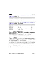
Page 14: ...t to the KXP 2290 transponder NOTE Connector 030 00101 0002 which accommodates RG 400 cable is included in the installation kit Con nector P N 030 00102 0001 is for larger diameter cables i e P N 024 00072 0000 and is not included NOTE The transmission line loss design value for the KXP 2290 is 0 5 to 2 0 dB Total line loss between the unit and the antenna must be within this specification The fol...

Page 15: ...e of instal lation of a new unit and again at two year intervals for any unit Other than the FAR noted above there are no periodic service requirements necessary to main tain continued airworthiness No maintenance is required until the equipment does not properly perform its intended function When service is required a complete performance test should be accomplished following any repair action Co...

Page 16: ...n KXP 2290 Rev 0c June 2006 Preliminary 05 24 06 10689I00 JA Page 1 6 THIS PAGE IS RESERVED ...

Page 17: ...ake a visual inspection of the unit for evi dence of damage incurred during shipment If a claim for a damage is to be made save the ship ping container to substantiate the claim When all equipment is removed place all packing mate rials in the shipping container for future storage or reshipment of the unit 2 3 EQUIPMENT INSTALLATION 2 3 1 GENERAL The following paragraphs contain information pertai...

Page 18: ...f the wires to parallel pins should be approximately the same length so that the best distribution of current can be effected Honeywell recommends that all wires including spares as shown on the interconnect diagram be included in the fabrication of the wiring harness However if full wiring is not desired the installer should ensure that the minimum wiring requirements for the features and functio...

Page 19: ...nector pin precautions should be taken to ensure each segment of the shielded lead be grounded at only one point A ground connection of not more than two inches in length should be used The preceding discussion does not apply to coaxial and quadraxial cable 6 Avoid routing cabling near high noise and high power sources 7 Do not route the transponder antenna coax s near ADF sense or loop antenna ca...

Page 20: ...rer s data sheets to determine the nanosecond delay per foot at 1030 MHz for the type or types of cable selected 2 3 2 2 Primary Power and Circuit Breaker Requirements and Wiring The KXP 2290 transponder receives primary power from the aircraft power circuit breakers The KXP 2290 is designed to operate over the range of 18 32V dc Power connections wire sizes and circuit breaker requirements are sh...

Page 21: ...he ADF sense antenna Where practical plan the antenna location s to keep cable lengths as short as possible and avoid sharp bends in the cable to minimize the VSWR Avoid running other cables or wires near the antenna cable s On pressurized aircraft the antenna s should be sealed using an approved sealant such as RTV No 3145 P N 016 01082 0000 or equivalent around the connector and mounting hardwar...

Page 22: ...on is received from the APEX system via the ARINC 429 bus NOTE THE AIRCRAFT MODE S ADDRESS MUST BE OB TAINED FROM FAA AND PROGRAMMED INTO THE KXP 2290 FOR US REGISTERED AIR CRAFT THE ICAO AIRCRAFT ADDRESS CODE CAN BE FOUND ON THE AIRCRAFT REGISTRA TION AIRCRAFT MODE S ADDRESSES MAY BE OB TAINED BY CALLING THE FAA AIRMAN AND AIR CRAFT REGISTRY DIVISION AT 405 954 3116 IF THREE 3 OR MORE ADDRESSES A...

Page 23: ...ompany 21615 SW TV Hwy Beaverton OR 97006 503 642 9853 Fax 503 591 7766 Email sales astrotool com Daniels Manufacturing Company DMC 526 Thorpe Road Orlando FL 32824 8133 USA Tel 407 855 6161 Fax 407 855 6884 Email dmc dmctools com Positronics Industries Inc 423 N Campbell Ave P O Box 8247 Springfield MO 65801 Tel 800 641 4054 Fax 417 866 4115 Email info connectpositronics com TABLE 2 1 SIZE 22 HIG...

Page 24: ...n KXP 2290 Rev 0c June 2006 Preliminary 05 24 06 10689I00 JA Page 2 8 THIS PAGE IS RESERVED ...

Page 25: ...are 2 429 RX A Reserved 6 I Spare 3 429 RX A Reserved 7 I XPDR 1 2 Reserved 8 I Serial Data In Reserved 9 O Serial Clk Reserved 10 I Conc 429 RX A Concentrated A429 input bus 11 I Spare 4 429 RX A Reserved 12 I GPS 1 429 RX A GPS ARINC 429 input 13 I GPS 2 429 RX A GPS ARINC 429 input 14 O GP 2 429 TX B Reserved 15 O GP 2 429 TX A Reserved 16 I 28 Vdc Power Return Aircraft Ground 17 I 28 Vdc Power...

Page 26: ...Time Mark for precision ADS B 35 O Serial Data Out Reserved 36 I GPS Mark 2 B GPS Time Mark for precision ADS B 37 I XPDR 1 2 Parity Reserved 38 O 3 3 Vdc Reserved 39 O EXT EEPROM CS Reserved 40 I RS232 Diag RX Diagnosis Input 41 O RS232 Diag TX Diagnosis Output 42 I O ARINC Supr I O As an input voltage 18 V and 70 V will cause suppression A steady state voltage 18 V will cause the suppression to ...

Page 27: ...n KXP 2290 Rev 0c June 2006 Preliminary 05 24 06 10689I00 JA Page 2 11 FIGURE 2 2 KXP 2290 INSTALLATION DRAWING Dwg 155 01786 0000 Rev B Sheet 1 of 4 ...

Page 28: ......

Page 29: ...n KXP 2290 Rev 0c June 2006 Preliminary 05 24 06 10689I00 JA Page 2 13 FIGURE 2 2 KXP 2290 INSTALLATION DRAWING Dwg 155 01786 0000 Rev B Sheet 2 of 4 ...

Page 30: ......

Page 31: ...n KXP 2290 Rev 0c June 2006 Preliminary 05 24 06 10689I00 JA Page 2 15 FIGURE 2 2 KXP 2290 INSTALLATION DRAWING Dwg 155 01786 0000 Rev B Sheet 3 of 4 ...

Page 32: ......

Page 33: ...n KXP 2290 Rev 0c June 2006 Preliminary 05 24 06 10689I00 JA Page 2 17 FIGURE 2 2 KXP 2290 INSTALLATION DRAWING Dwg 155 01786 0000 Rev B Sheet 4 of 4 ...

Page 34: ......

Page 35: ...n KXP 2290 Rev 0c June 2006 Preliminary 05 24 06 10689I00 JA Page 2 19 FIGURE 2 3 KXP 2290 BAR CLAMP ASSEMBLY DRAWING 300 10452 0000 Rev ...

Page 36: ......

Page 37: ...n KXP 2290 Rev 0c June 2006 Preliminary 05 24 06 10689I00 JA Page 2 21 FIGURE 2 4 KA 61 INSTALLATION DRAWING Sheet 1 of 2 ...

Page 38: ......

Page 39: ...n KXP 2290 Rev 0c June 2006 Preliminary 05 24 06 10689I00 JA Page 2 23 FIGURE 2 4 KA 61 INSTALLATION DRAWING Sheet 2 of 2 ...

Page 40: ......

Page 41: ...n KXP 2290 Rev 0c June 2006 Preliminary 05 24 06 10689I00 JA Page 2 25 FIGURE 2 5 KXP 2290 INTERCONNECTION DRAWING Dwg 155 0xxxx 000x Rev Sheet 1 of 2 ...

Page 42: ......

Page 43: ...n KXP 2290 Rev 0c June 2006 Preliminary 05 24 06 10689I00 JA Page 2 27 FIGURE 2 6 KXP 2290 INTERCONNECTION DRAWING Dwg 155 0xxxx 000x Rev Sheet 2 of 2 ...

Page 44: ......

Page 45: ...n KXP 2290 Rev 0c June 2006 Preliminary 05 24 06 10689I00 JA Page 2 29 FIGURE 2 7 RF CONNECTOR DRAWING ...

Page 46: ......

Page 47: ...n KXP 2290 Rev 0c June 2006 Preliminary 05 24 06 10689I00 JA Page 2 31 FIGURE 2 8 RG 400 CABLE CONNECTIONS DRAWING Option For Short Antenna Cable Lengths ...

Page 48: ...n KXP 2290 Rev 0c June 2006 Preliminary 05 24 06 10689I00 JA Page 2 32 FIGURE 2 9 ECS ECS RG 400 CABLE CONNECTIONS DRAWING Options For Longer Antenna Cable Lengths ...

Page 49: ...n KXP 2290 Rev 0c June 2006 Preliminary 05 24 06 10689I00 JA Page 2 33 FIGURE 2 10 CABLE CONNECTOR DRAWING ...

Page 50: ...e 2006 Preliminary 05 24 06 10689I00 JA Page 2 34 FIGURE 2 11 TYPE N AND C CONNECTOR ASSEMBLY DRAWING PART NUMBER SIZE DIMENSION RG U CABLE A B C D 024 00075 0000 393 9 32 1 8 5 32 3 64 024 00051 0060 400 9 32 1 8 5 32 3 64 ...

Page 51: ...n KXP 2290 Rev 0c June 2006 Preliminary 05 24 06 10689I00 JA Page 2 35 FIGURE 2 12 BNC CONNECTOR ASSEMBLY DRAWING ...

Page 52: ...n KXP 2290 Rev 0c June 2006 Preliminary 05 24 06 10689I00 JA Page 2 36 THIS PAGE IS RESERVED ...

Page 53: ...t and adjust cable runs to ensure that cables are not strained kinked or severely twisted and are not exposed to rough or sharp surfaces 2 4 1 2 Post Installation Checkout Operation 1 General Installation of the transponder system requires three stages of testing to ensure the proper operation of the Mode S transponder Initially prior to the installation of the transponder and antenna a system int...

Page 54: ...3 2 KXP 2290 INTERCONNECTION AND CABLE HARNESS FABRICATION b Using the interconnect diagram see FIGURE 2 5 KXP 2290 INTERCON NECTION DRAWING check wiring for proper destination opens and shorts c Check rf cables for insertion loss and VSWR 3 Visual Inspection In conjunction with system installation perform the inspection check procedure TA BLE 2 4 INSPECTION CHECK PROCEDURE 4 Post Installation Tes...

Page 55: ...minary 05 24 06 10689I00 JA Page 3 1 SECTION III OPERATION 3 1 GENERAL The only current operational function of the KXP 2290 is as a part of the Honeywell APEX system Consult the applicable APEX system operation handbook s as required ...

Page 56: ...n KXP 2290 Rev 0c June 2006 Preliminary 05 24 06 10689I00 JA Page 3 2 THIS PAGE IS RESERVED ...

Page 57: ...n KXP 2290 Rev 0c June 2006 Preliminary 05 24 06 10689I00 JA Page TSO 1 ENVIRONMENTAL QUALIFICATIONS APPENDIX ENVIRONMENTAL QUALIFICATION FORM S ...

Page 58: ...n KXP 2290 Rev 0c June 2006 Preliminary 05 24 06 10689I00 JA Page TSO 2 THIS PAGE IS RESERVED ...

Page 59: ...n KXP 2290 Rev 0c June 2006 Preliminary 05 24 06 10689I00 JA Page TSO 3 ...

Page 60: ...n KXP 2290 Rev 0c June 2006 Preliminary 05 24 06 10689I00 JA Page TSO 4 ...

Page 61: ...n KXP 2290 Rev 0c June 2006 Preliminary 05 24 06 10689I00 JA Page TSO 5 ...

Page 62: ...n KXP 2290 Rev 0c June 2006 Preliminary 05 24 06 10689I00 JA Page TSO 6 THIS PAGE IS RESERVED ...

Reviews: