
RA-2000 Remote Annunciator
Installation
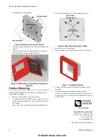
The optional Model RA-2000 Remote Annunciator, shown in
Figure 1, performs the same functions as the on-board
annunciator. Operation is identical. The RA-2000 can be surface
or flush monted.
Up to 8 RA-2000s can be added to the IFP-2000 system.
Figure 1: Model RA-2000 Remote Annunciator
RA-2000 installation involves the following steps:
1.
Make sure power is off at the panel.
2.
Mount the RA-2000 in the desired location (see Section
“Mounting the RA-2000” ).
3.
Connect the RA-2000 to the panel (see Figure 2).
4.
Use the dipswitches on the back of the RA-2000 to assign
an ID# to the RA-2000 (see Section 4.10.1 of Manual P/N
151430).
5.
The RA-2000 module must be added to the system through
programming. JumpStart AutoProgramming will add the
module automatically (refer to Manual P/N 151430).
Wiring Connections
Wire the RA-2000 to the FACP as Shown in Figure 2.
Figure 2: SBUS Connections
Specifications
Mounting the RA-2000
This section of the manual describes mounting the remote
annunciator. The annunciator can be flush- or surface-mounted.
Flush Mounting
This section of the manual describes flush mounting.
Follow these steps to flush mount the RA-2000
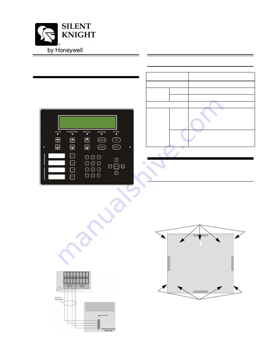
1.
The back box dimensions are 9-3/8" w x 8-3/8" h. The
minimum depth 2". The back box can be mounted prior to
the complete installation of the RA-2000 using any of the
mounting holes shown in Figure 3.
Figure 3: Back Box Mounting Holes
2.
Remove knockout holes as needed for wires. See Figure 4
Parameter
Value
Operating Voltage:
24 VDC
Current
Standby:
25 mA
Alarm:
50 mA
Operating Temperature: 0° to 49° C (32° to 120° F)
Dimensions:
Flush
Mount:
Overall: 12-1/4” W x 11.5” H x 7/8” D
31.1 cm W x 29.2 cm H x 2.2 cm D
See “Flush Mounting” for back box
dimensions.
Surface
Mount:
Including trim ring:
12-1/4” W x 11.5” H x 3” D
31.1 cm W x 29.2 cm H x 7.6 cm D
Mounting Holes
Mounting Holes
firealarmresources.com


