background image

Summary of Contents for 9122D

Page 1: ...HP 91220 5 Disc Drives Service Manual Manual part number 5957 6559 Printed APRIL 1988 Printed in U s A rL HEWLETT a PACKARD HEWLETT PACKARD Edition 2 E0488 P O Box 39 Boise Idaho 83707 0039 ...

Page 2: ... incidental or consequential damages in connection with the furnishing performance or use of this material HEWLETT PACKARD assumes no responsibility for the use or reliability of its software on equipment that is not furnished by HE N l ETT PACKARD This document contains proprietary information which is protected by copyright All rights are reserved N J part of this document may be photocopied rep...

Page 3: ...printing unless it appears as a prior update the edition does not change when an update is incorporated A software code may be printed before the date this indicates the version level of the software product at the time the manual or update was issued Many product updates and fixes do not require manual chang es and conversely manual corrections may be done without accompanyi gproduct changes Ther...

Page 4: ......

Page 5: ...ne Voltage Select Switch 2 1 Fuses 2 1 Power Cords 2 1 Selecting the Device Address 2 2 Disc Compatibility 2 3 ControIs and Indicators 2 4 Media Monitor 2 5 Power On Selftest 2 5 Write Protect Error on Initialization 2 5 Chapter 3 Page Interface Information 3 1 HP IB Interface 3 1 Instaiiation 3 1 HP IB Interface Restrictions 3 1 Chapter 4 Troubleshooting Page 4 1 Repair Philosophy 4 1 Non Exchang...

Page 6: ... Troubleshooting Proc dures_ _ _ _ _ _ 4 6 Troubleshooting Flowchart 4 7 Using the 55 80 Exerciser 4 11 DERRORS 4 11 Hints on Using the 55 80 Exerciser 4 12 Adjustments 4 14 PLL Adjustment 4 14 Chapter 5 Assembly Access Page 5 1 Introduction 5 1 9122D 5 Parts List 5 1 Chapter 6 Product History Page 6 1 Introduction 6 1 5 ervice Note History 6 1 f ...

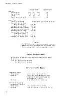
Page 7: ...eR designed using the SUBSET 80 command set Refer to the Subset 80 Reference Manua PN 595 8 4129 for a complete description of this command set Technical Specifications Number of drives Net Weight Height Depth Width Interface HP Double Density Format Encoding Rotational Speed Bit Density 600 RPM Track Density Tracks per Surface Surfaces used per disc HP 9122S HP 9122D 1 2 3 6kg 8 5 lbs 76 mm 2 99 ...

Page 8: ...s 497 ms NOTE 256 16 70 66 plus 42 ms settling The HP 9122 disc drives spare four complete tracks and reserve two tracks for system use with double sided formats and spare four tracks in single sided format Power Requirements 86 125 volts or 195 250 volts 67 watts RMS 94 voltamps 50 60 Hertz Fuse lA 250 for 115V setting 5A 250 for 230V setting Operating Limits Temperature HumiditY Altitude Non ope...

Page 9: ...91 220 S Disc Drive The disc drive was carefully inspected before shipment Remove the unit from the shipping carton and carefully inspect the unit for any physical damage that may have occurred during shipment If you find any damage you should immediately notify the dealer and file a claim with any carriers involved CAUTION I The disc drive is a precision instrument Mechanical shock can misalign t...

Page 10: ...hat contain ammonia benzenes chlorides or abrasives Before cleaning the case disconnect the power cord and HP IB cables Make sure that any disc is removed from the drives Dampen a clean soft lint free cloth in a solution of clean water and mild soap Vipe the soiled areas of the case making sure that no cleaning solution gets inside the case For cleaning more heavi ly soiled areas a solution of 80 ...

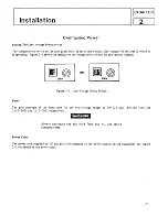
Page 11: ... select switch for the various voltages g OR 11SV Figure 2 1 Line Voltage Select Switch Fuses The part numbers of the fuses used for the two voltage ranges of 90 125 and 180 250 VAC are 2110 0001 and 2110 0012 respectively Power Cords A f 5 Always disconnect the disc drive from any AC line before changing fuses The power cord supplied by HP has polarities matched to the power sockets on the equipm...

Page 12: ... mass storage information of your controller for aJdressing inf Jrma tiCin concerning mass storage devices See Figure 2 5 for switch loca tions An HP IB address of 0 is set at the factory before shipment Prior to setting the device address switches turn the disc drive AC line switch OFF This is because part of the seIftest and power up sequen e includes a check to see what the address switch setti...

Page 13: ...tails the recommended usage of single sided and double discs Words used in the table are defined as follows Exchange only means that the disc should be used only for exchanging data and programs with single sided disc drives and should not be used on a daily basis OKII means that the disc may be used on a daily basis Single sided HP disc exchange only Double sided HP media in OK single sided forma...

Page 14: ...ht Irttake Slel I I i I 9122 Il II It V r ll i 2 Disc Access Light Disc Eje t Button for Drive 0 for Drive 0 E J 7 AC POW SWitCh 7r Selftest Indicato View ed through Air Lntake Slots ISenol num r p fix 2614A and above I for Drive 1 II V t ll If Disc Ejec t Butto for Drive 1 Disc Ac ess Ught for Drive 1 AC INPUT n 10 O o 1 O fl LU o L o O _ JO I IJ 0 l i ADDRESS TEST SELECT HP IB IALL serial number...

Page 15: ...ed by a WRITE READ test if an initialized non write protected disc is inserted When a WRITE test is performed it is done on a reserved area of the disc and no user data is at risk The Selftest LED acts as a pass fail indicator and is visible through the air intake slots When an initialized unprotected disc is inserted read write and motor speed tests are performed A write protected disc will not a...

Page 16: ......

Page 17: ...drive when the disc access light is on doing so can cause loss of data HP IB Interface Restrictions 1 All the AC line switches of the host system must be turned OFF when connecting and disconnecting devices to the system 2 The total length of cable permitted in one bus system must be less than or equal to two metres times the number of devices connected together the interface card is considered on...

Page 18: ...metres 4 The max imum number of devices that can be connected together in a one bus system is 15 There are no restrictions to the way cables may be connected together however it is recommended that no more than four piggyback conneGtors be stacked together on one device The resulting structure could exert enough force on thf connector mounting to damage it 3 2 ...

Page 19: ...001 2110 0012 09122 69511 09122 69514 09114 69511 09123 69101 Non Exchange Assemblies Description SIN Prefix 2614A and above RIBBON CABLE ASSEMBLY X RIBBON CABLE ASSEMBLY FAN ASSEMBLY X DC POWER CABLE LINE FILTER ASSEMBLY X FUSE 1A 250 VOLT X FUSE 1 2A 250 VOLT X Exchange Assemblies Controller PCA Controller PCA X 3 1 2 inch disc drive 3 1 2 inch disc drive X SIN Prefix 2518A and below X X X X X X...

Page 20: ...ives 9122S or 9122D respec tively J7 is used to start the service tests Jumper J6 is shown in the 91220 position and J7 is shown in the normal operating position 4 2 SW1 TP1 o TP 2 o L __ D J5 pu R11 CJ CJ JJ J4 09122 69501 TPt 5VOC TP2 12VOC TPJ IZVOC TP4 GNO TP5 INDEX TP6 TRKO TP7 READ DATA TP8 WRITE DATA TP9 eNO TPl0 5VOC TP1 1 Re o eLK 0 TP J LED1 SELFrEST LED HP 18 SELECT CODE 1 f L o tt ip r...

Page 21: ...d J 4 C Read Data Not used With Slimline drives Fuse F2 is for 5 1 and 12 suppies Fuse F3 is for 12V and the fan P2 TP1 5V I R t I R11 TP2 12 1 12 Selftest LED Pll Adj TROUBLESHOOTI G SW3 Select Code P1 1000001 i J7 J6 Figure 4 2 Controller and Power Supply PCA 09122 69504 4 3 ...

Page 22: ...11 Verify disc 12 Format disc 0 4 4 Test Time 1 2s 1 2s 1 2s 1 2s 2 3s 2 3s 2 35 2 3s 2 min min min min min Test DescriPtion All patterns are written in all locations of RAM A checksum calculation is performed Two of the registers are written and their content verified Two of the registers are written and their content verified Commands are given to the FOe to move the head on and off of track o T...

Page 23: ...able To initiate a test perform the following 1 Apply power to the unit and allow the power on selftest to complete 2 Install formatted unprotected discs if tests 6 through 14 are to be performed Note Scratch discs should be used as some tests destroy the data and format 3 Set the HP IB ADDRESS switch SW3 to the desired test number see figure 4 3 4 Short the TEST jumper pins 17 see figure 4 1 or 4...

Page 24: ... sided HP media is being used heavily with the HP 9122 instead of its intended use to exchange data with single sided disc drives and with media from other vendors Note that the head resonance problem may be found occasional ly as an independen t failure mode also Additional media related problems may occur as failure to initialize media and intermittent failures In some cases media may cause an a...

Page 25: ...edures Refer to pages 4 4 and 4 5 for information on the tests and how to perform the tests SYSTEM TROUBLESHOOTING POWER QN SELFTEST WIO MEDIA POWER QN SELFTEST W MEDIA NO NO YES TROUBLESHOOT PER PO TROUBLESHOOT PERP1 TROUBLESHOOT PER P2 CORRECT SYSTEM CONFIG TROUBLESHOOT PER P3 TROUBLESHOOT PER P4 4 7 ...

Page 26: ...lace the controller power PCA 91225 If any of Tests 0 3 fail then replace controller power PCA If Tests 3 pass replace the drive mechanism PROCEDURE P2 Fails power on selftest with media installed 1 Perform Tests 6 and 7 measures index period or perform MTR_5PO test using the 55 80 Ex erciser SERve module If disc access light comes on but drive fails then replace drive Ii disc lccess light does no...

Page 27: ...ess light did not come on replace the controller first if failure persists replace original controller and change the drive mechanism If 55 80 Exerciser is not available perform the following 1 If a computer which supports the 9122 is available attempt to INITIALIZE or FORMAT using appropriate host commands on each drive This tests the read write capability of the drive and the controller power PC...

Page 28: ... and 13 If vne drive fails then replace the failing drive mechanism If both drives fail then perform test 14 If Te st 14 fails then adjust the PLL per procedure on page 4 14 If PLL adjustment does not correct the problem or cannot be made then replace the controller power PCA Perform Test 14 If test fa ils then adjust the PLL per procedure on page 4 14 If PLL adjustment does not correct the proble...

Page 29: ...wn good disc such as one containing prerecorded software Test 10 may be used for this purpose Infrequent read or write errors The recommended method of verifying this type of failure is to use the tests in the R W_TEST module of the SS 80 Exerciser These tests tra nsfer data and when an error occurs the status information will provide an indication of the possible cause of the problem Refer to pag...

Page 30: ...t computer and the peripheral and to performs certain tests which cannot be implemented in any other way Please refer to the 5S 80 Exerci ser manual PIN 5958 4142 for an overview of the capabilities contained in the Exerciser Some general testin solutions which can be implemented using the Exerciser are as f llows HP IB channel test Testing for R W errors General product evaluation Flexible dISC t...

Page 31: ... 4 5 for the proper setting of the drive select switch o o o F ACTORY SETTINGS DRIVE 0 2 DRIVE 1 J o 0 a 0 o 0 o 0 a 0 o 0 elsc ORNE St L CT SWITCH o 0 o a a o 0 o 0 o o a o 0 o Figure 4 4 Disc Drive Select Switch 091l4 69 511 Figure 4 5 Disc Drive Select Switch 09123 69101 4 13 ...

Page 32: ...ls the PLL test TEST I n Use figure 4 1 or t 2 for locating test points 4 14 1 Power on the unit and allow the power on selt test to finish 2 After two minutes warm up attach the frequency counter test leads to tht veo test point TP 11 The freque lcy should be 500K Hz 5 If adjustment is necessary adjust the variable resistor R 11 for a frequency of 500 KHz l 1 KHz 3 Verify disc operation ...

Page 33: ... 2 C9 18 27 30 2 C24 2 Ct 20 21 2 C2 3 15 16 2 C6 2 C7 NOTE When installing drives for units having a S N prefix of 2614A and above the controller PCA or the disc drive cable P N 09123 61611 ensure that the disc drive cable is placed between the drive and the controller PCA Also all star washers removed during disassembly must be reinstailed These steps will ensure that the 91220 S will conform to...

Page 34: ...F 237 OHM 1 2 R14 16 17 18 0698 3445 R F 348 OHM 11 2 R15 19 o75 0280 R F lK 1 125W R28 075 0411 R F 332 OHM 11 2 R2 6 8 075 0417 R F 562 OHM 11 2 R12 13 20 29 o75 7 0442 R F 10 0K 1 8W R31 34 42 43 R44 2 09121 00611 SHIELD TRANS 2 T1 o91 1 8250 0 TRANSFORMER 2 Tl 09121 82501 XFMR SUPPORT 2 U40 09122 15511 IC SONY DSCTL E 2 ROM SOCKET 1200 0861 SKT Ie 28 CONT 2 120S 0500 HEATSINK 2 PLSTC GASKET 12...

Page 35: ...826 0555 IC L 1340LAZ 5 2 U11 12 1854 0611 XSTR 2N6055 NPN 2 U3 5 1858 0058 XSTR ARY MPQ3906 2 U13 1884 0074 IC 2N5060 2 CR1 3 1901 0050 010 SWITCHING 2 CR4 1901 0518 010 SM SIG S 2 CR5 12 1901 1135 DIO PWR 3A 70V 2 CR2 1902 0029 DIO ZNR 12V 5 2 CRT4 1902 0040 DIO ZNR T4V 5 2 CR13 1902 0074 DIO ZNR 7 15V 5 2 LEDl 1990 0450 LED LMP 2 U26 1LH4 000 1 TRANSCEIVER 2 RI0 2100 0554 R V 500 OHM 10 2 F1 21...

Page 36: ...ERM 2 J2 0360 2035 CONN SGL CONT 2 0590 0305 NUT HEX 6 32 2 RI 39 068 3 1015 R FlO0 OHM 05 2 R4 26 37 38 40 068 3 1025 R F 1K 5 25 4 R41 49 2 R46 48 068 3 1035 R F 10K 05 1 4W 2 R30 068 3 1045 R F lOOK 05 2 R23 24 068 3 1205 R F 12 5 25W 2 R32 33 068 3 1245 R F 120K 05 2 R34 068 3 2735 R F 27K 05 2 R7 068 3 5655 R F 5 6K 05 2 R5 0698 0082 R F 464 OHM 11 2 R3 0698 3132 R F 261 OHM 01 2 R36 0698 313...

Page 37: ... 2 U17 30 1820 1416 IC SN74LS14N 2 U20 23 1820 1433 IC SN74LS164N 2 U35 1820 2024 IC SN74LS244 2 U36 1820 2046 IC SN74LS353N 2 U18 33 1820 2096 Ie SN74LS393N 2 U25 1820 2549 Ie 8291AP 2 U39 1820 2624 Ie 68B09 2 U21 29 1820 2624 Ie 74FOO N 2 U22 1820 2686 Ie 74F08 PC 2 U38 1820 3006 Ie MB8876A CTLR 2 U37 1820 3318 Ie SN74ALS273N 2 U4 6 1821 0001 XSTR ARRAY CA3046 2 Ul 1826 0210 IC LM361 2 U8 1826 0...

Page 38: ...5 6 ...

Page 39: ...ASTIC 09121 48302 PILLAR SUPPORT 09121 48303 FOOT MOLDED 09121 61611 RIBBON CABLE ASSEMBLY 09123 61611 RIBBON CABLE ASSEMBLY Assembly Access SIN prefix 2518A and below SIN prefix 2614A and above 09121 61612 DC POWER CABLE SIN prefix 2518A and below 09121 68511 FAN ASSEMBLY 5041 1203 PWR BUTTON WHITE 2360 0117 6 32 SCREW EXCHANGE ASSEMBLIES 091 14 69511 FLEXIBLE DISC DRIVE SIN PREFIX 2518A AND BELO...

Page 40: ...1 or 09123 69101 FLEXIBLE DISC DRIVES D c D 0 I OOQO OOOOQO l J 4 J3 a DO CONTROLLER POWER SUPPLY 09122 6951 1 or 09122 69514 a FAN 09121 68511 Location of Field Replaciable Assemblies FRA 5 8 I I Jl 0 L 0 l 0 I I J 1 C I 0 J C ...

Page 41: ...9114 69510 09114 69511 New drive electronics 91220 2 3 1 2 inch drive and ALL 09114 69511 Cassette up assembly 91220 3 Potential Service Test failure 2518A and 09122 69501 Firmware update needed above 91220 4 Controller Power supply generates noise 2513A and 09122 69501 Affects Read AMP New Controller PN 09122 69511 below 91220 5 New shipping disc Drive date codes 09114 69511 PN 1535 4881 2418 or ...

Page 42: ......

Page 43: ...s shipped prior to September 1984 contained only the one rear mounting screw The exchange drive is now being shipped with the MAXIMUM number of screws to accommodate all products that use the drive DESCRIPTION The 91220 requires the following Min Required Must Be Removed Drive 0 1 2 3 4 5 Drive 1 1 2 3 4 5 If the required screws are not in the exchange drive use screws from the original removed dr...

Page 44: ...LM tm 2012 3 I I 1 2 1 1 4 I I 1 I 1 I I I I I I Top View I I I I I I I 1 1 1 5 I I 1 I 1 I 1 1 1 1 S ield Mounting Screw Locations ...

Page 45: ...will be stocked with the same exchange part number and no FSI action is required Cause The drive is being changed to reduce cost and improve reliability The new drive has fewer parts to increase reliability Warranty Both drives will be used interchangeably using exchange part number 09114 69511 No F S I or warranty action is required KK tm 9320 4766 1 83 4 9 85 5800 rhO HEWLETT PACKA D FOR MORE IN...

Page 46: ......

Page 47: ...d Format Tests Tests 12 and 13 ONLY No other tests or functions are effected Solution The New E PROM part n mber 09122 15513 corrects timing problems for both the earlier and later drives The Controller Power PCA part number 09122 69501 date code 2513 and later has the new E PROM 09114 69511 E PROM PN E PROM PN Drive Date Code 09122 15512 and earlier 09122 15513 and later 2418 and 2432 Will pass S...

Page 48: ......

Page 49: ... all Controller Power Supplies PN09122 69501 for credit and reorder using PN09122 69511 We have not shipped drives with date codes 2513 or 2514 as repair inventory If these drives are shipped as repair inventory they will be tested to ensure they have adequate nois rejection to meet our specification with any Controller Power Supplies that have been shipped Warranty Units that have been shipped ha...

Page 50: ......

Page 51: ...lder cardboard shipping disc PN 1535 4881 can be used with both the newer and older drives The new plastic shipping disc will also have part number 1535 4881 The old cardboard shipping disc does not eject as smoothly as the new plastic disc in the new drives but careful handling when removing the disc from the drive will not damage the drive Implementation CPC will use up all old cardboard shippin...

Page 52: ......

Page 53: ...hipping disc vibration and shock can easily damage the heads Other damage could occur if the customer perceives that the shipping disc although slightly ejected is ready to install or remove from the drive When the disc or media is installed or ejected without first pressing the eject button to unload the heads head damage can occur This damage may be either loosening of the top head caus ing fail...

Page 54: ... instruction sheet with the driv All drives in FSI should have the rub ber wedge installed immediately Any drives received in FSI with the ship ping disc ejected should be returned to CSR or CSE No drive mechanisms should be shipped without the rubber wedge RP 9 23 85 FOR MORE INFORr IlTION CALL YOUR LOCAL HP SALES OR SERVICE OFFICE or East 201 265 5000 Midwe at 312 25 5 9800 Soout h 404 955 1500 ...

Page 55: ...9511 09122 69511 assemblies are required SiN prefix 2614A 09123 69101 09122 69504 Cables required for service of the 9122D are as fopows s m prefix 2518A SiN prefix 2614A 09121 61611 09123 61611 09121 61612 Not required to service the 91220 DescriptiOn 3 5 inch flexible disc drive Controller PCA Desc ript ion Ribbon cable O C power cable The 09123 69101 is currently used in the 9123D with serial p...

Page 56: ......

Page 57: ...unting standoffs ar e attached Solution The drive casting threads may be damaged if the_sta doffs are tightened the 6 5 inch pound or 0 734 newton meter torque specification If there is of measuring the torque when attaching the standoffs to the drive mech hand tighten the standoffs DO NOT OVERTIGHTEN RP 5 10 86 beyond no way firmly b i K OR MORE INfORMATION CALL YOUR LOCAL HP SALES OR SERVICE OfF...

Page 58: ......

Page 59: ...ard if either the drive mechanism or controller board has been replaced This incompatability will NOT appear on new uni ts that have n at had the drive mechanism or cont roller replaced Solution Return all 09122 69504 controller boards to SMR or CSG for upgrade to n ew part number 09122 69514 R P 12 19 86 P R MORE INFOR TION CRLL YOUR LOCAL HP SALES OR SERVICE OFFICE or East 201 265 5000 Midwest 3...

Page 60: ......

Page 61: ...imately Mar 1 1987 The new shipping disc will have part number 1150 1786 for the full height drive 09114 69511 or 91220 s with serial number prefix below 2614A The part number 1s 1150 1787 for the shipping disc used on the slim line drive 09123 69101 or 91220 s with serial number prefix 2614A and above PCE and CPC will stock the new shipping discs and will use the old discs and wedges until gone T...

Page 62: ......

Page 63: ...Manual Part Number 5957 6559 Printed in U S A APRIL 1988 Edition 2 E0488 F a HEWLETT a PACKARD ...

Reviews: