


Summary of Contents for ProBook 450 G8
Page 4: ...iv Safety warning notice ...
Page 8: ...viii ...
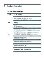
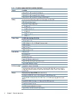
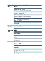
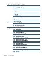
The HP ProBook 450 G8 is a versatile and reliable laptop designed for productivity. Ensure proper care and troubleshooting with the comprehensive Maintenance and Service Manual. Download this manual for free from 88.208.23.73:8080, empowering you to optimize your device's performance and longevity.
Page 4: ...iv Safety warning notice ...
Page 8: ...viii ...


