background image


HSB Automation GmbH 
In Laisen 74 
72766 Reutlingen 
Germany 
Tel. +49 7121 14498-0 
Fax +49 7121 14498-10 
Info@HSB-Automation.de 
www.hsb-automation.de 

FM 239 Master-MuW-Anleitung Beta-Typ-Z Rev.01 

 
Distributor:  
SCHUNK GmbH & Co. KG  
Spann- und Greiftechnik  
Bahnhofstr. 106 - 134  
74348 Lauffen/Neckar 
Germany 
Tel. +49 7133-103-0  
Fax +49 7133-103-2399  
info@de.schunk.com  
www.schunk.com 


distributed by 


Original  
Assembly and 
Maintenance 
Instructions 


Linear Unit 


Type 

Beta 60-ZSE 

Beta 80-ZSE 

Beta 110-ZSE 


Summary of Contents for Beta 110-ZSE

Page 1: ...n de FM 239 Master MuW Anleitung Beta Typ Z Rev 01 Distributor SCHUNK GmbH Co KG Spann und Greiftechnik Bahnhofstr 106 134 74348 Lauffen Neckar Germany Tel 49 7133 103 0 Fax 49 7133 103 2399 info de schunk com www schunk com distributed by Original Assembly and Maintenance Instructions Linear Unit Type Beta 60 ZSE Beta 80 ZSE Beta 110 ZSE ...

Page 2: ......

Page 3: ...rranty 6 3 Technical data standard design 7 4 Product description 10 5 Transport and storage 11 6 Assembly and alignment 12 6 1 Assembling the linear unit with mounting brackets 12 6 2 Screwing linear unit into place from underneath 13 6 3 Setting the maximum stroke 14 6 3 1 Adjusting the position of the inductive limit switches 14 6 3 2 Adjusting the position of the mechanical limit switches 16 6...

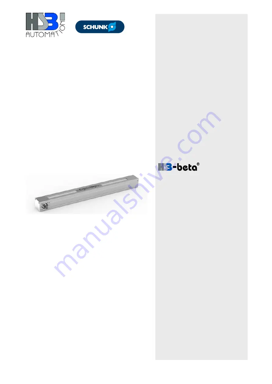
Page 4: ...ut these instructions Scope These instructions apply to the following linear unit with toothed belt drive Beta 60 ZSE Beta 80 ZSE Beta 110 ZSE The drawings show the type Beta 80 ZSE and are intended to be examples for all other types where details may appear different ...

Page 5: ... a danger carrying low risk Failure to comply with this instruction may result in minor or moderate injury or material damage Note Indicates tips for the operation and optimum use of the unit 1 2 Intended use The mechanical linear drive is designed for installation in machinery and is solely intended for manipulating positioning transporting palletising loading unloading clamping synchronising ten...

Page 6: ... unit in particular the technical data the Operating Instructions for the entire installation 1 4 Use in clean rooms ISO 14644 The linear units are not suitable for use in clean rooms and can also not be upgraded for this area 1 5 Use in potentially explosive areas The linear units are not suitable for use in potentially explosive areas and can also not be upgraded correspondingly 1 6 Technical co...

Page 7: ...n devices Follow the assembly instructions supplied by the manufacturer when using special attachment parts 1 8 Requirements for personnel The linear unit is manufactured using state of the art technology and in compliance with the recognised safety standards However there are still risks associated with its use Therefore only qualified and trained personnel are permitted to assemble and operate t...

Page 8: ...bels The operator must ensure that any lettering information signs or labels are fully legible in particular the serial number and always observed Any damaged or illegible information signs and labels must be replaced 2 Warranty The warranty conditions are specified in the sales documents delivery and payment conditions The warranty claim expires if the unit has not been used in accordance with it...

Page 9: ... 60 Idle torque Nm 1 00 1 40 3 35 Maximum stroke standard mm 7670 7600 7520 Repeat accuracy mm 0 08 0 08 0 08 Operating temperature C continuous operation 0 80 0 80 0 80 Geometrical moment of inertia IY mm 4 400283 1326597 4974348 Geometrical moment of inertia IZ mm 4 521983 1693634 5898662 Length of carriage mm 180 210 320 Weight without stroke kg 3 10 6 35 15 75 Weight per 100 mm stroke kg 0 53 ...

Page 10: ... Support Dynamic load ratings of Beta linear unit rail guides Unit size Size No of rails No of carriage s Load rating per carriage Cdyn N THK Rex Pretension FV N THK Rex Mt Nm THK Rex Guiding distance in direction x lx1 mm Beta 60 ZSE 15 1 2 11271 9860 564 620 60 74 106 Beta 80 ZSE 20 1 2 17700 23400 885 1500 210 240 131 Beta 110 ZSE 25 1 2 25160 28600 1258 1820 340 320 203 Values in refer to the ...

Page 11: ... clamping hub Size 14 19 24 28 38 Coupling diameter mm 30 40 55 65 80 Screw size M3 M6 M6 M8 M8 Tightening torque Nm 1 34 10 50 10 50 25 00 25 00 Tightening torques Nm for coupling with clamping ring Size 14 19 24 28 38 Coupling diameter mm 30 40 55 65 80 Screw size M3 M4 M5 M5 M6 Tightening torque Nm 1 34 2 90 6 00 6 00 10 00 ...

Page 12: ...linear guide system and a drive element toothed belt drive Depending on the design the carriage can absorb forces and moments in all directions and is non positively connected to the guide and drive element via the attachment The basic profile is self supporting up to a certain length and fitted with slots to keep it in place Optionally the linear unit can be fitted with accessories such as induct...

Page 13: ...eavy impact or bending Only transport an assembled linear unit using transport locks In order to avoid any damage to the linear unit when storing or transporting it the following measures must be taken in order to protect it from jolting or slipping Transport the unit in a sufficiently large container Use cushioned packaging The weight values for the units are listed in Section 3 The units must be...

Page 14: ...Mounting the linear unit using the threaded rails is recommended for the following situations for highly dynamic applications where the linear unit is attached at only 2 fixing points 6 1 Assembling the linear unit with mounting brackets Figure 2 Mounting brackets 1 The recommended maximum distance between the mounting brackets is 700 mm Proceed as follows 1 Loosely fit the mounting brackets 1 int...

Page 15: ...1 in the slot on the underside of the basic profile Secure the linear unit using fastening screws from below using the sliding blocks or the threaded rails in the basic aluminium profile Figure 3 Proceed as follows 1 Align the linear unit 2 Align the sliding blocks 1 threaded rails 3 Screw the linear unit into place for tightening torques refer to Section 3 ...

Page 16: ...e connected by a qualified electrician Allow for a sufficient braking distance to ensure that there is enough time to slow down the carriage in the case of an emergency stop 6 3 1 Adjusting the position of the inductive limit switches The duty of the inductive limit switches is to shut down the electric drive before the mechanical limit of travel is reached The necessary braking distance Δ B depen...

Page 17: ...the power supply for the limit switches 2 Loosen the fastening screws for the limit switch 3 Move the carriage up to the braking position 4 Move the limit switch NC far enough under the switching cam for it to trip and the LED on the sensor to go out 5 Move the carriage away 6 Tighten the limit switch fastening screws 7 Check the correct position of the limit switch Move the carriage along by hand...

Page 18: ...orrectly adjusted and are connected Mechanical safety limit switches may be combined with inductive limit switches External dampers must be fitted as protection against mechanical damage The necessary braking distance Δ B depends on the speed and deceleration This braking distance must be less than the distance between the trip point of the limit switch and the actual mechanical limit of travel Fi...

Page 19: ...ollows 1 Switch on the power supply for the limit switches 2 Loosen the clamping screw for the retaining plate Figure 5 3 Move the carriage up to the safety area 4 Push the limit switch along until it trips 5 Tighten the clamping screw on the retaining plate 6 Check the correct position of the limit switch Move the carriage along by hand and check the switch tripping point If this leaves insuffici...

Page 20: ...he limit switches operate correctly Legend 1 Safety area 3 Carriage with direction of travel plus and minus from the reference point 0 2 Limit switch minus direction 4 Limit switch plus direction Figure 6 Example of direction of travel and limit switch circuits 6 4 1 Installing the motor Legend 1 Coupling half 1 4 Motor mounting 2 Coupling collar D Diameter at motor mounting 3 Coupling half 2 Figu...

Page 21: ...meter is smaller than the D measurement at the motor mounting 4 first mount the coupling half 1 1 bore flush with the drive shaft and then the motor mounting 4 Figure 7 If the coupling diameter is larger than the D measurement at the motor mounting 4 first mount the motor mounting 4 and then the coupling half 1 1 bore flush with the drive shaft Tighten the coupling clamping screw using the mountin...

Page 22: ...ve hood supplied is not permitted Only qualified electricians are permitted to carry out any work on the electrical installation or check the direction of rotation Checking the unit before commissioning Before commissioning the following must be checked whether the holding devices used are consistent with the mass and acceleration information provided by the manufacturer whether the machine or ins...

Page 23: ...ns may result in foreign objects entering the linear unit In order to prevent this the operator must take the necessary measures to avoid the ingress of foreign objects e g folding plates wash plates sealing air Required inspection The linear unit must be occasionally checked during operation to see that it is functioning correctly The personnel responsible must check the linear unit and the machi...

Page 24: ...move excessive dust and dirt from the cover band and other parts of the linear unit regularly The toothed belt is maintenance free Replace the toothed belt should there be any breakage or stretching beyond the elastic area 10 1 Lubrication Influencing factors The following influencing factors are important for an accurate regulation of lubrication intervals Load Speed Motion sequence Operating tem...

Page 25: ... part built onto the carriage For this purpose there is a recess in the lubricating hole in which an appropriate O ring 1 is inserted as a seal Lubrication points for linear units with optional carriage plate Fig 9 Lubrication point 1 on the carriage on both sides The linear guide system can be relubricated at one of the two lubrication points 1 Lubrication method Lubrication should take place as ...

Page 26: ...ant manufacturer Grease with a solid lubricant percentage e g graphite MoS2 must not be used 20 with ball chain approx 0 6 25 with ball chain approx 1 2 15 without ball chain approx 2 000 km approx 0 8 20 without ball chain approx 1 4 25 without ball chain approx 2 8 Or at least twice a year The lubrication interval depends on the ambient conditions and the load Relubrication in motion Figure 9 Re...

Page 27: ...ding carriage will not be ensured Legend 1 Carriage plate 2 Threaded bores for jacking 3 Attachment 4 Tensioning screws 5 Toothed belt holder 6 Bearing housing 7 Basic profile 8 Top part of toothed belt holder 9 Toothed belt 10 Alignment pins Figure 10 Replacing the toothed belt Proceed as follows 1 Remove the drive motor gearbox 2 Move the carriage into the middle of the linear unit 3 Remove fast...

Page 28: ...s onto the basic profile The fastening screws must be secured with Loctite 243 14 Fasten both toothed belt holders to the attachment using the tensioning screws but do not tension The tensioning screws must be secured with Loctite 243 15 Place the toothed belt under high tension using tensioning screws 16 Set the required tension accurately using a belt tensioning measurement device see Operating ...

Reviews: